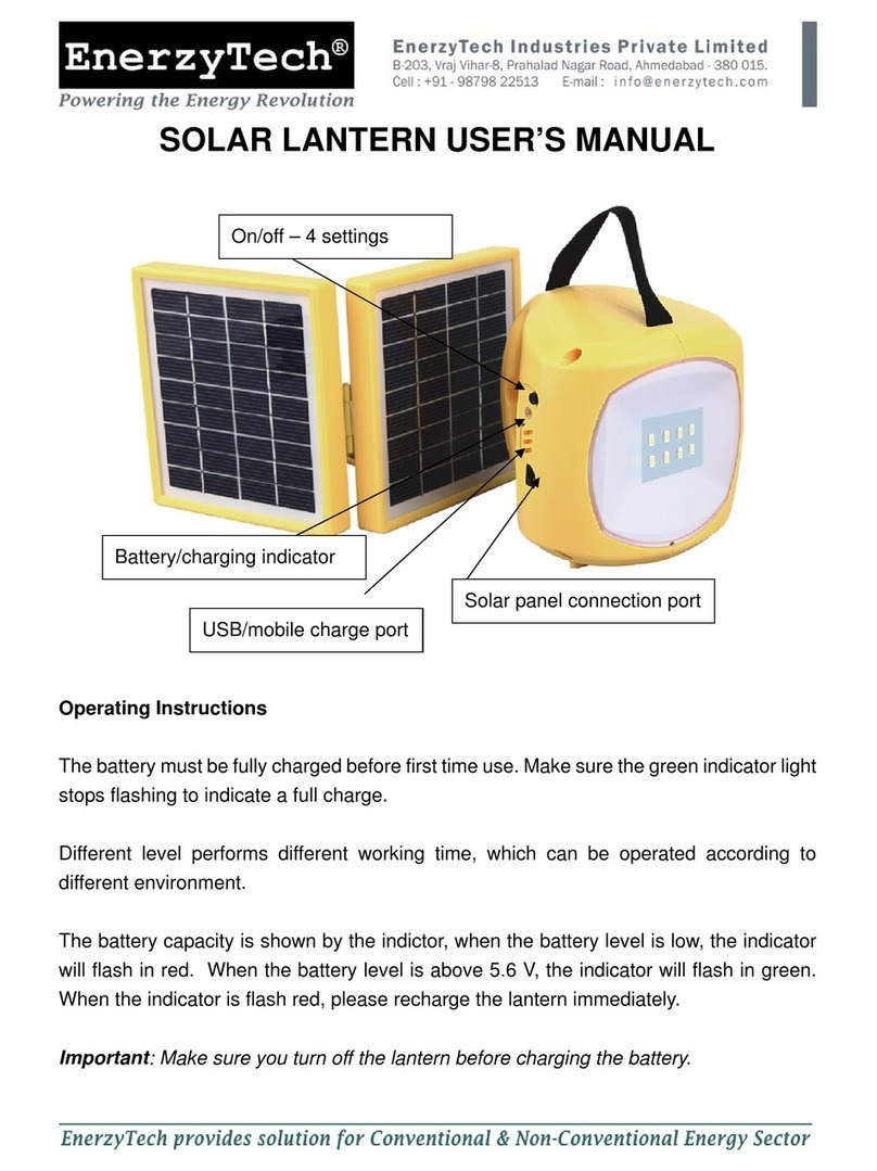
Solarbotics PumLantern User manual

PumLantern
PumLanternPumLantern
Ltd.
®
®
The
Skill Level:
Beginner
(Soldering Reqd.)
Document Revision: May 21, 2009
2 hrs
Charge all day & pulse all night with
a solar-powered night-light!
The PumLantern’s SCC3733 solar cell stores
power all day to release it in pleasant
“pumms” of multicoloured light all night long!

This page is intentionally left semi-blank.
Yeah, it was going to be completely blank, but we needed to put that
boring legal-type stuff somewhere. We were going to say “use this
marvelous empty page as you blank canvas with which to create such
illustrations or notes as to change the very fabric of society.” Instead
it’s now a partially text-populated page with a large and awkward
empty portion in the middle. Feel free to use it however you want.
www.solarbotics.com 1-866-276-2687
Page 2
Boring Legal-Type Stuff:
“SOLARBOTICS” is a trademark of Solarbotics Ltd. Reg. CIPO / USPTO.
Disclaimer of Liability
Solarbotics Ltd. is not responsible for any special, incidental, or consequential
damages resulting from any breach of warranty, or under any legal theory, including
lost profits, downtime, good-will, damage to or replacement of equipment or
property, and any costs or recovering of any material or goods associated with the
assembly or use of this product. Solarbotics Ltd. reserves the right to make
substitutions and changes to this product without prior notice.

Lantern Sides x4
Lantern Top x1
CP1000 F x2µ
74HCT240 x1
SCC3733 x1
DC-20 Pin
Chip Carrier x1
CP0.47 x5µ
D2 x1
SBLED x4
SWire x5”
R100k x1
R1.5M x1
R2.2M x1
R4.7M x1
R6.8M x1
BHoldAAA x1
BattAAA x2
DSST x1
PARTS
SKU Name . . . . . . . . . . . . . . . . . . . . . . . . . . . . . . . . . . . . . . . . . Qty
74HCT240 Octal Inverting Buffer. . . . . . . . . . . . . . . . . . . . . . . . . . . . . . . . . . . . . . . . 1
BattAAA Rechargeable AAA Battery . . . . . . . . . . . . . . . . . . . . . . . . . . . . . . . . . . . . 2
BHoldAAA 2 x AAA Battery Holder. . . . . . . . . . . . . . . . . . . . . . . . . . . . . . . . . . . . . . . 1
CP0.47µF 0.47µF Monolithic Capacitor. . . . . . . . . . . . . . . . . . . . . . . . . . . . . . . . . . . 5
CP1000µF 1000µF Electrolytic Capacitor. . . . . . . . . . . . . . . . . . . . . . . . . . . . . . . . . . 2
D2 Schottkey Barrier Diode . . . . . . . . . . . . . . . . . . . . . . . . . . . . . . . . . . . . . . 1
DC-20 Pin 20 Pin DIP Socket Carrier . . . . . . . . . . . . . . . . . . . . . . . . . . . . . . . . . . . . . 1
DSST Double-Sided Sticky Tape (1” Square) . . . . . . . . . . . . . . . . . . . . . . . . . . . 1
KPL-PCB PumLantern PCB. . . . . . . . . . . . . . . . . . . . . . . . . . . . . . . . . . . . . . . . . . . . 1
Lantern Sides . . . . . . . . . . . . . . . . . . . . . . . . . . . . . . . . . . . . . . . . . . . . . . . . . . . . . . . . 4
Lantern Top . . . . . . . . . . . . . . . . . . . . . . . . . . . . . . . . . . . . . . . . . . . . . . . . . . . . . . . . . 1
R100k 100k ohm resistor (Brown, Black, Yellow). . . . . . . . . . . . . . . . . . . . . . . . . 1
R1.5M 1.5M ohm resistor (Brown, Green, Green) . . . . . . . . . . . . . . . . . . . . . . . . 1
R2.2M 2.2M ohm resistor (Red, Red, Green) . . . . . . . . . . . . . . . . . . . . . . . . . . . . 1
R4.7M 4.7M ohm resistor (Yellow, Purple, Green) . . . . . . . . . . . . . . . . . . . . . . . . 1
R6.8M 6.8M ohm resistor (Blue, Grey, Green). . . . . . . . . . . . . . . . . . . . . . . . . . . 1
SCC3733 37 x 33mm Polycrystalline Solar Cell . . . . . . . . . . . . . . . . . . . . . . . . . . . . 1
SBLED Super Bright LED . . . . . . . . . . . . . . . . . . . . . . . . . . . . . . . . . . . . . . . . . . . 4
SWire 5” of Twisted Wire. . . . . . . . . . . . . . . . . . . . . . . . . . . . . . . . . . . . . . . . . . . 1
Vellum (8”x2.875” rectangle) . . . . . . . . . . . . . . . . . . . . . . . . . . . . . . . . . . . . . . . . . . . . 1
PARTS LIST
Circuit Board
Vellum x1
www.solarbotics.com 1-866-276-2687
Page 3
Let’s get started. Start by opening your bag of parts, and dumping them into a safe
place like an egg-container (remove eggs), pie-plate (eat the pie), or cat-food bowl
(give cat away to gypsies). Don’t simply spread them about on a table-surface where
they’ll roll away, because then you’ll think we forgot something in the kit and have
to call us. Then we’ll tell you to look under your chair, and you’ll find it there and
think we have magic powers. In short, keep your parts safe when you dump them
out - they’re small, and will try their hardest to hide from you!

SOLDERING TUTORIAL
Solder
Soldering Iron
PCB Solder Pad
PCB
Component Leg
Bad
No flow from leg to pad
Good
Flows from leg to pad
Bad
Solder “bridge” across pads
Bad & Good Solder Joints
X
X
á
Remember to take your time. Don’t rush.
It’s almost impossible to “burn up” these parts!
The most important skill needed to successfully construct your device is
soldering. Make sure you start by using electronics solder, not plumber’s
solder. The main trick to getting a successful solder connection is to heat
the junction up before applying the solder to the heated area. Do NOT try
to melt some solder onto the tip of the iron and smear it onto the joint -
you won’t get a strong joint.
If the heat is applied unevenly, you will get solder blobs (see below). To
better apply heat,keep your soldering iron tip clean by wiping it frequently
on a damp sponge or cloth. The tip should always be shiny, and not
covered in tarnish and burned crud (don’t burn crud - bad!).
You’re a roboticist, not a painter!
www.solarbotics.com 1-866-276-2687
Page 4

Let’s start with mounting the chip
carrier to the printed circuit
board (PCB).It makes it easier to
install the actual chip later.
Note the notch on the carrier,
and make it match the notch on
the PCB.
Installation hint: Put the carrier
in, then fold over a leg or two to
keep it locked in. It keeps it from
falling out!
STEP 1: CHIP CARRIER
www.solarbotics.com 1-866-276-2687
Page 5
BUILDING IT!
Step 1:Install
Chip Carrier
Notch
The way the PumLantern “Pums” is determined by resistors R1 and R2 - the
bigger the resistor, the longer the time interval between Pums. Some
people like frequent blips; others more sleepy longer intervals. Or mix ’em
up for a more random light show.
Choose what Pum interval you’d like:
0.3 seconds - use 1.5M (Brown, Green, Green)
0.6 seconds - use 2.2M (Red, Red, Green)
1 seconds - use 4.7M (Yellow, Purple, Green)
1.5 seconds - use 6.8M (Blue, Grey, Green)
R1 controls the Pum behavior of LED1 & LED2; R2 controls LED3 & LED4.
Not that it really matters, but some people like to have fanatical control
over how their devices work.
May we suggest you start with the 2.2M and 6.8M?
STEP 2: THE FINE ART OF RESISTOR SELECTION
Did you pay close attention to those soldering instructions? Well, now it’s
time to put your new skill to use...
1.5M (Brown, Green, Green)
2.2M (Red, Red, Green)
4.7M (Yellow, Purple, Green)
6.8M (Blue, Grey, Green)

www.solarbotics.com 1-866-276-2687
Page 6
Start by installing your selected R1 and R2 resistors. Put the 100k resistor
(Brown / Black / Yellow) for position R3. R3 sets the dark “turn-on”
sensitivity. Lower values make it turn on earlier in the evening. Be careful
installing the D1 diode! Note the position of the band, and make it match
the position printed on the PCB!
Step 3a: R3
100k Resistor
(Brn/Blk/Yel)
Step 3b: R1
2.2M Resistor (Red/Red/Grn)
(or your choice)
Step 3d: R2
4.7M Resistor (Yel/Purp/Grn)
(or your choice)
Four capacitors work with the R1 and R2 resistors to make the timing
circuit that drives the PumLantern. The fifth capacitor works with the 100k
R3 resistor’s “dark turn-on” circuit.
These capacitors don’t care which way they are installed. Just snug them
down to the PCB, solder them in, and clip off the extra leads.
STEP 4: 0.47µF CAPACITORS
Step 4: Install 0.47µF
capacitors in locations
C3, C4, C5, C6, and C7.
(Yes, we know we skipped
C1 and C2, but we’ll get
back to them - honest)
STEP 3: RESISTOR & DIODE INSTALLATION
Tip:
After you put the part in, bend the
leads so it stays in while you solder!
Step 3c: D1 Diode
Note where
the band is!

STEP 5: LEDS101 - OR “HOW SILICON LIGHTS UP MY LIFE”
Light Emitting Diodes (”LEDs”) make the light. The ones in your kit are
sooper-dooper bright, designed for maximum PUM. Some have a flat top,
which makes them spread their light even wider than the regular type.
Important things to learn about LEDs: They have a cathode (-) and an
anode (+), which means you have to learn which is which. There are 3
easy ways:
1) The anode is the longer leg. Remember this by thinking of
the + sign as two legs ( “|” and a ” –” ). Add these lengths up,
and it’s longer than the cathode (just “ –” ).
2) If you look carefully at the LED itself, you will see it has a
flat shoulder, which marks the cathode ( – ).
3) Look carefully into the LED. The cup side is always the
cathode ( – ).
Method 1:
Longer lead =
Anode ( + )
Method 2:
Flat spot =
Cathode ( – )
Method 3:
LED Cup =
Cathode ( – )
www.solarbotics.com 1-866-276-2687
Page 7
Your PumLantern lights the LEDs up in pairs LED1 & LED3, and LED2 &
LED4, so if you want to colour-arrange your LEDs, here is an easy way to
check them.
Step 1: Arrange LED so
anode (+) matches solar
cell’s oval pad, and
cathode (–) matches
rectangular pad Step 2: Pinch down
the leads to the pads
hard with your thumb
and finger.
Step 3: Hold up to lamp.
Look at the pretty colour!

Step 6: Bend 1000µF capacitor leads
over right next to capacitor body. One
to the right, the other to the left.
www.solarbotics.com 1-866-276-2687
Page 8
Step 5: Install the LEDs in locations
LED1 - 4, matching flat spot on the LEDs
to flat drawn on PCB.
Installation check: ALL the LED cups will look the same. Either
they will be all right, or all wrong (we have confidence in you!)
STEP 5: LEDSCONTINUED...
With all this knowledge, now you won’t have any problem installing the
LEDs so the cathode side matches the flat-spot marked on the PCB in spots
LED1-4, right?
Install, solder, snip!
STEP 6: PREPARING THE LARGE 1000µF CAPACITORS
The 1000µF capacitors actually store the extra “Pum” power in the circuit.
Fold them like this. Just like this. One cap’s leads to the right, the other
cap’s leads to the left.
See the stripe on the side? That’s the cathode, which should be easy for
you to identify because you’re expert at identify-the-cathode-by-the-lead-
length now.

STEP 7: INSTALLING THE 1000µF CAPACITORS
www.solarbotics.com 1-866-276-2687
Page 9
Step 7: Install caps
so long lead goes
through “+” pad
STEP 8: INSTALL THE 74HCT240 CHIP
Remember the first step where we put in the chip carrier? Let’s put it to
work. We’re almost ready to power-test your Pummer!
Find the chip, and put it in the carrier, so the notch matches the notch on
the carrier. You might find it easier to put it in the carrier after bending in
the legs a bit by laying the legs on a surface and gently bending it over.
Step 8: Install 74HCT240 into the
carrier. Note the notch position
on the chip and carrier, and
make them match!
We had you fold over the capacitor leads before
soldering them in so you are sure not to leave
them standing straight up. If you do, they cast
strange shadows on the inside of your
PumLantern.
Make sure you install the
capacitors correctly. The longer
lead (anode +) is marked on the
board with a “+”, and is also the
round pad. The cathode (–) is
the square pad.

STEP 9: PUMMER TEST!
Time to see how good your soldering is!
Hopefully your batteries will have some charge. If not, charge’em up, or
use a pair of AAA cells (borrowed from a remote control), and stick them
into the AAA cell holder.
Insert the battery holder from the underside (opposite side to where you’ve
done all your work so far), and give it a bit of a bend so the leads make a
secure contact with the PCB. If all is well, you should see your 4 LEDs
jumping to life in a pleasant, pummer-ish manner...
Step 9a: Put fresh batteries in the holder,
and insert it from the bottom. These holes
are labeled “Batt” on the top of the PCB.
Step 9b: Tilt the board to the battery
holder pins so that they are for sure
making contact.
Step 9c: Inspect your handiwork!
You should see 4 blinky lights!
If you don’t see blinky lights, check:
!Batteries charged?
!Chip in right-way around?
!LEDs in right-way around?
There’s not much else that can go
wrong, so if nothing else, re-touch up
your soldering!
www.solarbotics.com 1-866-276-2687
Page 10

Step 10b: Wire red to oval pad,
and black to square pad
STEP 11: SOLDER IN THE BATTERY HOLDER
If you are sure all is well with your pummer, then go ahead and snug the
battery pack up to the back of the PCB. Solder it in and snip the leads.
Step 10a: Wire red to
“Solar +” and black
to square pad
STEP 10: ATTACHING THE SOLAR CELL
Pull the battery pack off, so it’s easier to solder the solar cell wires to the
PCB. This is pretty straightforward if you remember to solder red to “+”
and black to “–“.
Strip off a bit of insulation from the end of the wire by firmly pinching and
pulling it off between your thumbnail and index finger. Or use a proper
wire-stripping tool if you wish (but it’s not as much fun). Solder the red wire
to the PCB pad “Solar +”, and the black to the square pad next to it.
Do the same on the solar-cell end of the wire, red to the oval pad, and
black to the rectangle pad.
If all is well, when you hold the solar cell up to the light, the pummer will
stop working (and start recharging). Cover it with your hand, and it should
kick back to life!
www.solarbotics.com 1-866-276-2687
Page 11
Step 11: Solder in and
snip battery pack leads
You’re ready to assemble the lantern, and install your pummer!
Red (+)
Black (–)

STEP 12: POP THE PIECES OUT OF YOUR SIDES
Except your liver - you need that part. Our
laser-cut art should come out easily, but if
not, use a sharp knife to gently pop it out of
the frame.
We’ve done a lot of work to make assembly nice and tidy. Be gentle
(especially with delicate art), and it’ll turn out fine!
ASSEMBLING THE LANTERN
We’ve placed a little slit into the top of the lantern,
so all you have to do is flex the board and slip the
wire through the slot into the hole.
STEP 13: THREAD THE SOLAR CELL THROUGH THE TOP
We’re not going to hold your hand and tell you
about “Slot A”s and “Tab B”s. You’re old enough to
figure out what goes where. Just leave one side
completely open.
STEP 14: ASSEMBLE THREE SIDES AND THE TOP
Fold in half... then unfold. Fold side 1 to middle Fold side 2 to middle
Unfold until it holds
a sorta box-shape
Fold the vellum paper in half, then fold each end in 1/4 again.
Not clear? Here’s some pictures:
STEP 15: LANTERN ORIGAMI
www.solarbotics.com 1-866-276-2687
Page 12

Place the vellum inside the lantern, so that
each side sits flush with the lantern shell.
STEP 16: SLIDE THE VELLUM PAPER INTO THE LANTERN BODY
Use some careful tweaking, and you should
be able to mount the final side to the
PumLantern without problem.
STEP 17: ATTACH THE FINAL LANTERN SIDE
See those two notches on the
bottom? You need to get the tabs on
the end of your completed board in
there. Push the PCB into one slot,
then flex the other side until you can
pop the other tab into place.
STEP 18: POP THE PUMMER CIRCUIT INTO PLACE
Before you mount your cell, you
might want to think about where
your Pumlantern will live. It may be
best for the solar cell to be attached
to one side instead of the top, so it
better catches sunlight from a
window.
Peel one side of your double-sided
sticky tape, and press it onto the
solar cell.
Then peel the other side and press it
onto the top of the lantern. All done!
STEP 19: MOUNT THE SOLAR CELL
www.solarbotics.com 1-866-276-2687
Page 13

There’s two parts to the PumLantern. The “dark turn-on” circuit, and the
actual Pum circuit. Let’s start with the Pum circuit!
The Pummer is based around a very simple BEAM circuit called a “Bicore”,
which is simply an oscillator that has two outputs that change voltage.
When one is “high” (3V), the other is “low” (0V). Every so often, they trade
voltages.
We’re using this “trade voltage” behavior to create a charge-pump, which
is a fancy way of saying we’re building something that makes more voltage
than what it normally access to. Here’s how it works (showing only one
pair of LEDs in operation):
has
CIRCUIT THEORY
The stored 1.7V is
added to the normal
3V now flowing back, like
a second 1.7V battery!
When the output swap polarity, the
stored 1.7V is added to the 3V, and
the LED goes super bright from 4.7V!
0V
+3V
P
o
w
e
r
F
l
o
w
LED3
Super-bright PUM
from 4.7V!
LED1 (blocks
power flow)
+1.7V
With the bicore output + / -, it charges
the capacitor to ~ 1.7V, making LED1
light up while power passes through it.
+3V
0V
1000µF capacitor
charges up to 1.7V
(3V-1.3V=1.7V)
w
o
l
F
r
e
w
o
P
LED3
(blocks power
flow)
+1.7V
LED1 “eats”
1.3V as light
www.solarbotics.com 1-866-276-2687
Page 14
The “dark turn-on” circuit is pretty simple. The chip has an “enable-low”
line, which means when it sees zero volts, it turns on. We attach this line to
the solar cell, and when it stops generating power (sun goes down), the
100kOhm resistor forces the chip on. That simple!

E
E
74HCT240
0.47uF
LED1
LED2
R1
R2
C3
0.47uF
C6
0.47uF
0.47uF
C7
R3
D1
C1
C2
1000uF
1000uF
C4
0.47µF
LED3
LED4
SCC3733
2x
AAA
Here’s the actual circuit diagram of the PumLantern’s circuit. It’s more
useful for those of you who might want to modify your PumLantern, or
build a second out of parts.
SCHEMATIC
www.solarbotics.com 1-866-276-2687
Page 15
ADDITIONAL ENHANCEMENTS
You might have noticed that there are little pads on the tabs that stick out
of your PumLantern. Once side has a single square pad, which is the
ground pad that connects to common grounds in the circuit.
The other tab has two pads: One labeled “S” and one “B”.
The “S” pad lets you add an additional solar cell (connected between “S”
(+) and the ground pad). This lets you use a large cell and have it power a
whole string of lanterns at the same time.
The “B” pad lets you directly connect to the battery (with the ground tab)
for easy recharging, or measuring voltage.
Tab
Ground Pad
Tab “S”
Pad
Tab “B”
Pad

The SolarSpeeder 2 Kit is a very quick Solaroller
that can cover 3 meters (10 feet) in under 40
seconds in direct sunlight. Simple to construct and
a blast to watch, this is a great kit for all beginners!
K SS Solarspeeder $27.50 USD/CAD
Herbie the Mousebot is a 9-volt battery-powered
robot that loves to chase flash light beams. If there
are several Herbies in the same area, they can be
configured to chase each other! These little robots
are so quick, you have to run to keep up to them!
K HM Herbie the Mousebot $39.95 USD/CAD
Liked the PumLantern? Want more?
There are several more kits Solarbotics offers for any skill level!
201 35th Ave NE
Calgary, AB T2E 2K5
Canada
N. America Toll Free: 1-866-276-2687
Local / International: 403-232-6268
Fax: 1-403-226-3741
Find more neat kits, components, articles, resources and more at our official website:
www.solarbotics.com
Like the Mousebot, the K PP Photopopper seeks light
and avoids obstacles but is solar powered! It’s
pretty quick, covering a meter per minute (that’s 3.3
feet!). Newly upgraded with better electronics and
gold circuit board!
K PP Photopopper $45.00USD/CAD
This manual suits for next models
1
Popular Lantern manuals by other brands
Adventuridge
Adventuridge 52358 user manual

Coleman
Coleman Classic 8D user manual
Philips
Philips CoreLine BN120C Series Mounting instructions

Orion
Orion PUCHBERG AL 11K/82506 Mounting and safety instructions
Olimpia electronics
Olimpia electronics POWER LIGHT Series manual

Nuvo
Nuvo Parisian 60/2511 Assembly instruction
