SolarEdge StorEdge LG Chem RESU10H User manual

StorEdge™ Wiring Guide & On Site Checklist for North America
Revision History
Version 1.4 (November 2018)
Added support of LG Chem batteries with the disconnect switch.
Added battery self-test.
Version 1.3 –support for connection of 2 LG batteries
Version 1.2 –menu and checklist updates
Version 1.1 –support for LG batteries
Version 1.0 –initial version, using Tesla batteries
This document is a battery wiring guide and contains an on-site checklist with steps for post-installation verification of a StorEdge system, for the following batteries:
LG Chem RESU10H
CAUTION
For proper battery performance, the LG Chem battery should remain connected to the StorEdge Inverter and in charging mode. Extended battery
disconnection may result in deep discharge and damage the battery.
For more details, refer to the StorEdge Installation Guide supplied with the StorEdge Inverter. For additional assistance contact SolarEdge Support
(refer to the section
Support and Contact Information
on page 13).

2
Wiring Guide
WARNING!
The LG Chem battery must be powered off before wiring.
LG Chem batteries are available with either of the following two types of powering mechanism design:
With the disconnect switch (requires Firmware version 3.24xx or later)
With the auxiliary power switch
Figure 1: LG Chem Disconnect/Auxiliary Power Switch and Circuit Breaker
To power off the battery:
1. Turn off the circuit breaker.
2. Turn off the disconnect/auxiliary power switch.
To power on the battery:
1. Turn on the disconnect/auxiliary power switch.
2. Turn on the circuit breaker.
3
Wiring Types and Connectors
To connect the battery to the StorEdge Inverter, use the following wiring types and connectors:
Recommended Cable Type (min-max cross section)
SolarEdge Connector
LG Chem RESU10H Battery Connector
DC: 10 AWG (14-10 AWG), 600V insulated
Ground/PE: 10-8 AWG, 600V insulated
BAT DC +
DC +
BAT DC -
DC -
Ground
Control and monitoring:
5-wire shielded twisted pair cable, 24 AWG (24-16 AWG), 600V insulated.
CAT5 600V insulated can also be used.
En (enable)
ENABLE_H
V+
Not connected
B- (RS485)
RS485_L
A+ (RS485)
RS485_H
G (RS485) or Thermal (depending on inverter type)
EN_G
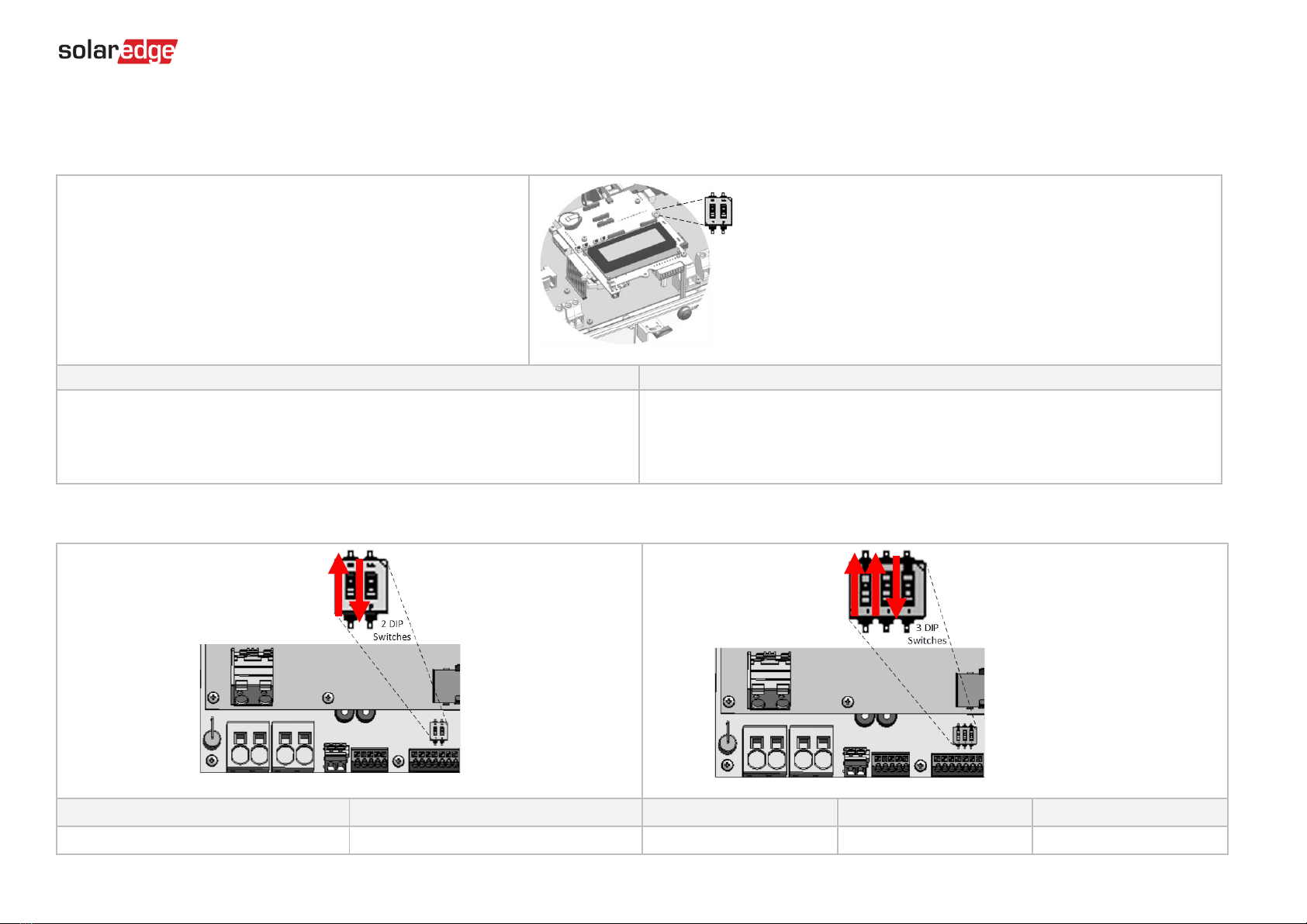
Wiring Diagrams –Connecting Batteries to the StorEdge Inverter
The diagrams on the following pages illustrate the connection of batteries to the StorEdge system. The following table will help you find the appropriate wiring diagram for your system
configuration. Pay attention to whether the battery DIP switch setup on the communication unit main board has 2 or 3 switches.
Battery Type
Connected to
Wiring Diagram
DIP Switches
LG Chem RESU10H
StorEdge Inverter with 2 DIP Switches
See Figure 2 on page 4
StorEdge Inverter with 3 DIP Switches
See Figure 3 on page 4
4
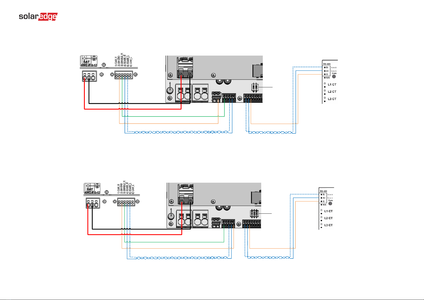
Connecting an LG Chem RESU10H Battery to a StorEdge Inverter with Two DIP Switches and SolarEdge Meter
2 DIP
Switches
24 AWG 300V
G <> G
LG Chem RESU10H Battery StorEdge Inverter SolarEdge Electricity Meter
B- <> B- and A+ <> A+ on the same twisted pair
RS485_H <> A and RS485_L <> B- on the same twisted pair
ENABLE_H <> En
EN_G <> Thermal-
24 AWG 600V
RS485-terminated
10 AWG (14-10 AWG) 600V insulated
Figure 2: Connecting an LG Chem RESU10H Battery to a StorEdge Inverter with Two DIP Switches and SolarEdge Meter
Connecting an LG Chem RESU10H Battery to a StorEdge Inverter with Three DIP Switches and SolarEdge Meter
3 DIP
Switches
24 AWG 300V
G <> G
LG Chem RESU10H Battery StorEdge Inverter SolarEdge Electricity Meter
B- <> B- and A+ <> A+ on the same twisted pair
RS485_H <> A and RS485_L <> B- on the same twisted pair
ENABLE_H <> En
EN_GND <> G
24 AWG 600V
RS485-terminated
10 AWG (14-10 AWG) 600V insulated
Figure 3: Connecting an LG Chem RESU10H Battery to a StorEdge Inverter with Three DIP Switches and SolarEdge Meter
5
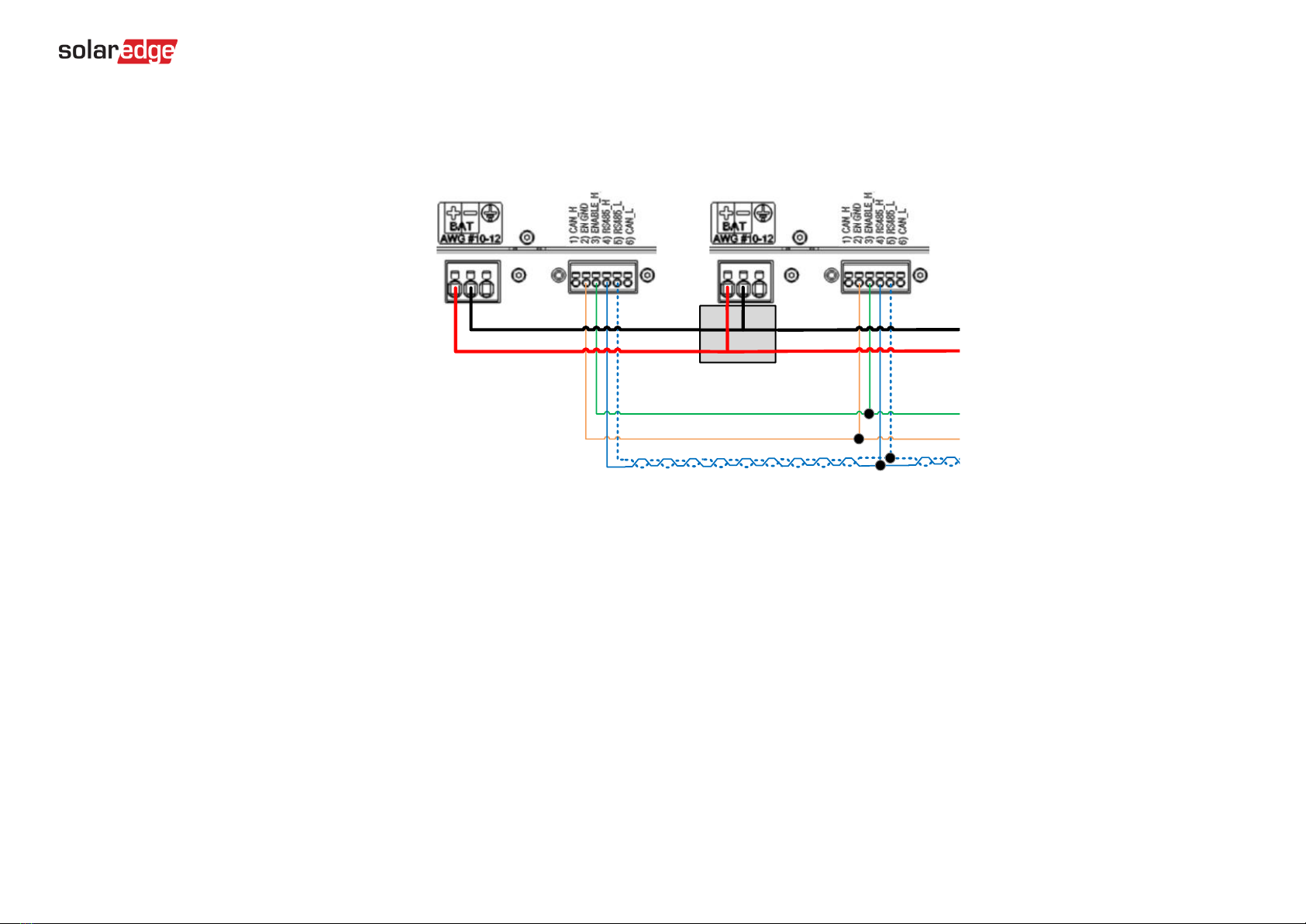
Wiring Diagrams –Connecting Two LG Batteries
LG Chem RESU10H
Battery #2
LG Chem RESU10H
Battery #1
ENABLE_H 24 AWG 600V
EN_GND
RS485_H and RS485_L on the same twisted pair
12-10 AWG
600V insulated
Junction Box
Figure 4: Connecting Two LG Chem RESU10H Batteries
6
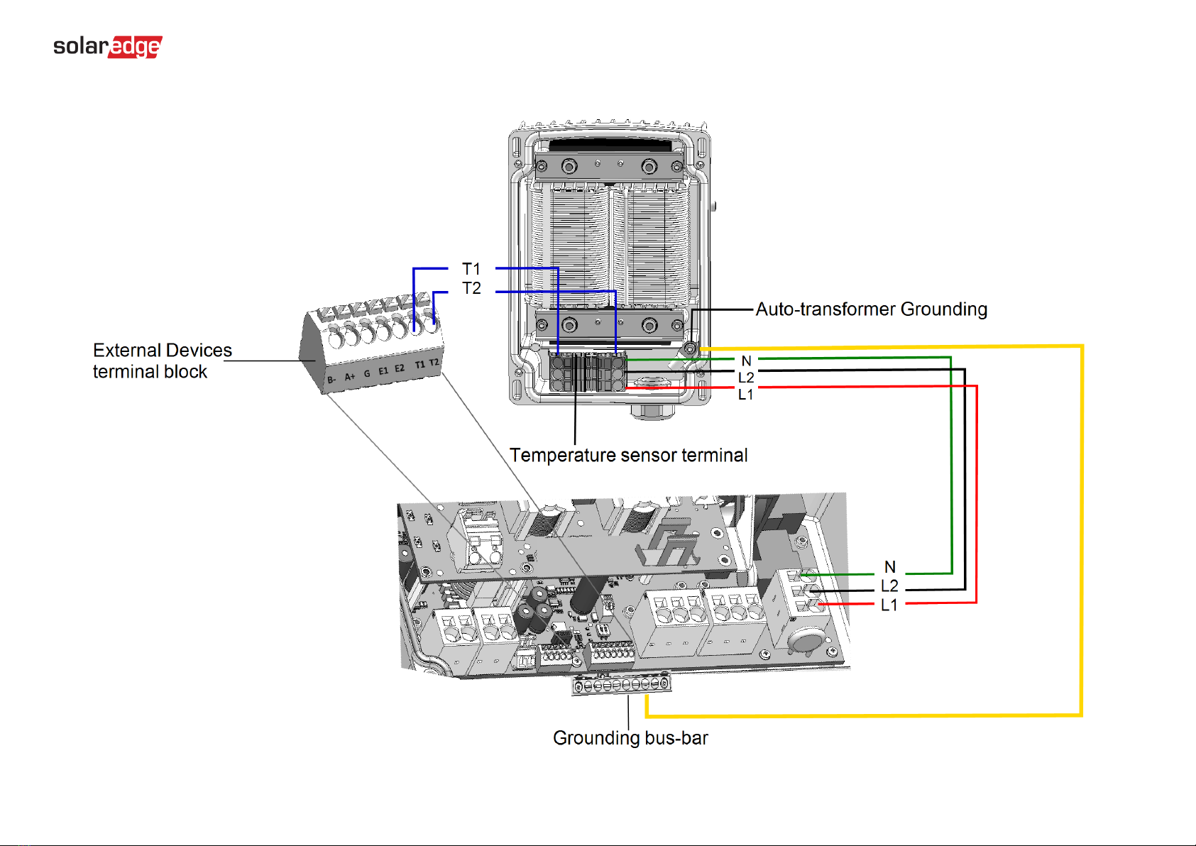
Wiring Diagrams –Auto-transformer Connection
Figure 5: Connecting the Auto-transformer to the Inverter
7
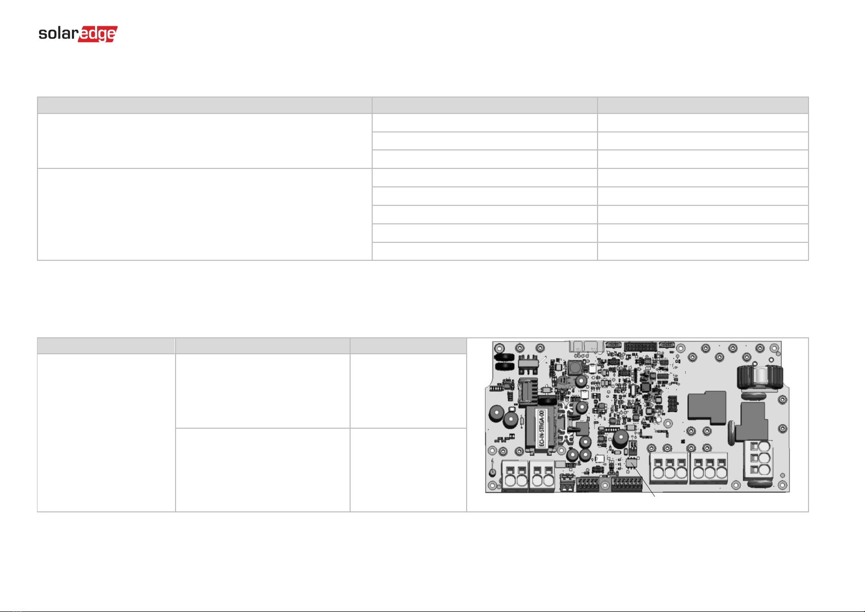
Switch Settings
Setting the DIP Switches on the Inverter Communication Board
Set DIP switch SW7
SW7
RS485-1
RS485-2
For RS485-1 connections, use DIP Switch 1 (leftmost):
* ON (up): Terminated (no meter installed)
* OFF (down): Not terminated (meter is installed)
For RS485-2 connections, use DIP Switch 2 (rightmost):
* ON (up): Terminated (no meter installed)
* OFF (down): Not terminated (meter is installed)
Setting the DIP Switches on the Inverter Connection Unit Main Board (with Two or Three DIP Switches)
DIP Switch 1 (leftmost)
DIP Switch 2 (rightmost)
DIP Switch 1 (leftmost)
DIP Switch 2 (center)
DIP Switch 3 (rightmost)
ON (up)
OFF (Down)
ON (up)
ON (up)
OFF (Down)
8
Post Installation Verification and Configuration
Follow the checklist below to verify that the system is properly connected and configured. The checklist is suitable for a backup system with a single StorEdge Inverter, a single battery, an
Auto-transformer and a single SolarEdge Electricity Meter installed at the grid connection point. For other system configurations, follow the steps in the StorEdge Installation Guide supplied
with the StorEdge Inverter.
Step
Verification Action
Checked
1
Installation and Wiring
1.1
Verify that the distance between components complies with the distances detailed in the supplied installation guide.
1.2
Take a photograph of the battery connection area and send to SolarEdge support (useful for future debugging if necessary.)
1.3
Take a photograph of the connection area of the StorEdge Inverter and send it to SolarEdge support.
1.4
Take a photograph of the installation and send to SolarEdge support.
1.5
Verify that the battery splash cover is closed.
1.6
Verify that the backed-up loads panel is wired (relevant for backup systems only).
1.7
Verify that the Auto-transformer’s AC and temperature sensor wires are connected as above in Figure 5.
1.8
Verify that the Inverter’s DIP switches are configured to connect to the Auto-transformer, as shown above in Figure 2 (for boards with two DIP switches), and
Figure 3 (for boards with three DIP switches).
1.9
Verify that all DC, communication and AC cabling connections are completed as follows:
1.9.1
Check AC wiring and circuit breaker.
1.9.2
Check string DC input voltage. Expect 1V per optimizer in the string.
1.9.3
Verify that grounding is properly connected in the battery and inverter.
1.9.4
Check DC wiring to the battery (see Table 1). Check the connections and verify that all are securely connected.
1.9.5
Check connections to the battery and the DIP switch setup as described earlier in this document.
1.9.6
Check connections to the meter. If no meter is connected, the inverter’s RS485 bus must be terminated using the DIP switches on the inverter’s
communication board (see page 7).
1.9.7
Check that a 9V battery is installed in the StorEdge Inverter.
1.9.8
Check connection to the Internet with one of the following options: Cellular, Ethernet, ZigBee Module. The connection status displayed should be S_OK.
Note: For inverters with a built-in cellular communication option, Ethernet or ZigBee Module can be used as an alternative if the cellular service does
not meet operational requirements.

9
2
Activation and Firmware Upgrade
2.1
Turn the inverter ON/OFF switch to OFF and make sure it's OFF during the entire upgrade process.
2.2
LG Chem Batteries (primary and secondary): Switch on the disconnect/auxiliary power switch and then the circuit breaker.
2.3
Turn the AC to the inverter OFF.
2.4
Verify that the serial number on the activation card supplied with the inverter matches the serial number of the inverter.
2.5
Insert the activation card to the designated slot located on the inverter communication board.
2.6
Turn ON the inverter ON/OFF switch.
2.7
Turn ON the AC to the inverter to start activation.
2.8
Wait until the LCD indicates that the inverter activation process is completed.
2.9
Turn the AC to the inverter OFF.
2.10
Remove the activation card from the inverter.
2.11
Download the latest firmware version available at: https://www.solaredge.com/storedge/firmware to a microSD card.
2.12
Insert the microSD card with the upgrade file to the designated slot located on the inverter communication board.
2.13
Turn the AC to the inverter ON.
2.14
Wait until the LCD indicates that the file was uploaded to the inverter and the battery.
Note: The firmware is upgraded first on the inverter, and then on the battery. When the battery firmware update is in process, the ON light will blink.
10
3
RS485 Configuration Verification (for one battery, a StorEdge inverter with built-in production meter (RGM), and one Export + Import meter)
3.1
If not already OFF, switch OFF the StorEdge DC Safety Switch.
3.2
Switch the inverter ON/OFF switch to OFF.
3.3
Devices
3.3.1
Enter Setup mode and select Communication > RS485-1 Conf > Multi Devices
3.4
Meter
3.4.1
Select Communication > RS485-1 Conf > Meter 1 > Meter ID: 1, Device Type <MTR>, Protocol <WN>, CT Rating (as per CT label), Device ID <2>, Meter
Function (Production).
3.4.2
Select Communication > RS485-1 > Meter 2 > Meter ID: 2, Device Type <MTR>, Protocol <WN>, CT Rating (as per CT label), Device ID <2>, Meter
Function (E+I).
3.4.3
Verify Device Type > Revenue Meter
3.4.4
Verify Protocol > Meter
3.4.5
Verify that the CT value matches the value that appears on the CT label: CT Rating > <xxxxA>.
3.4.6
If CT resets to 0, check the communication with the meter.
3.5
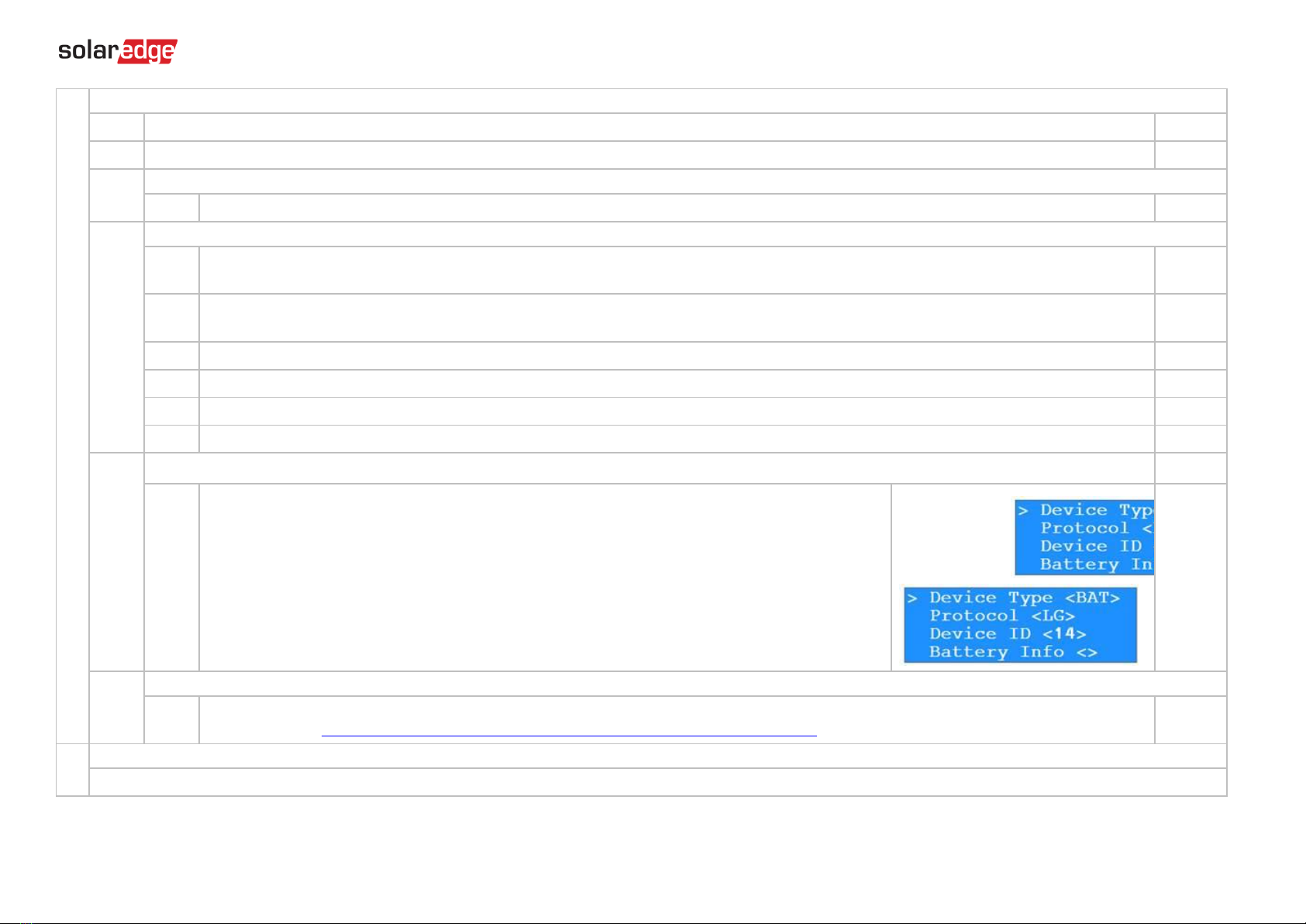
Battery
3.5.1
Select Communication > RS485-1 > Battery 1 > Protocol (LG Battery).
Select Communication > RS485-1 > Battery 1 > Battery ID (15).
If installing
two batteries
, ensure that each battery has a
different part number
–thus ensuring that each
battery will have a different Battery ID. The part number is printed on a label on the control panel of the
battery. Battery with part number RXXXXXXXXSEG1XXXXXXXXX and ID 15 is the
master
battery.
Battery with part number RXXXXXXXXSEG2XXXXXXXXX and ID 14 is the
secondary
battery.
To configure the second battery:
Select Communication > RS485-1 > Battery 2 > Battery ID (14).
3.6
Optional: RS485 Expansion Kit
3.6.1
For a system with multiple inverters that has a single RS485 bus only, install and configure an RS485 Expansion Kit. Refer to the RS485 Expansion Kit
Installation Guide. http://www.solaredge.com/files/pdfs/RS485_expansion_kit_installation_guide.pdf
4
RS485 Connection Verification
Press the inverter external LCD light button to display the status screens one after the other until a screen like the following is displayed:

11
4.1
Check the RS485 communication status:
Verify that the number under Prot displays the number of configured devices.
Verify that the number under ## displays the number of communicating devices.
4.2
Check the meter(s): In the meter(s) status screen check that the status is OK. If Comm. Error appears, refer to the
troubleshooting section in the supplied installation guide.
4.3
Check the meter AC and CT connections, including the CT direction. Connect the meter to power supply.
Check the LEDs: when configured as export/import meter: green=import, red=export.
To verify whether the CT direction is correct, turn the inverter ON/OFF switch to OFF, and check the export screen. If the screen indicates “export”, the CT
direction should be reversed.
5
Battery Self-test
The test is available in CPU version 3.24xx and higher (but not in version 4.x.xxx).
If two batteries are installed, the active battery will be tested first, and then the standby battery. If the active battery fails the test, the test will stop and the standby battery will not be
tested.
5.1
Verify that AC is ON.
5.2
Turn the inverter ON/OFF switch to ON.
5.3
Make sure the Connection Unit is ON.

12
5.4
Enter Setup mode and select Maintenance → StorEdge Self-Test → Start Test. The battery charges and discharges within approximately two minutes to check
performance.
During the test, the following message is displayed:
Upon the test completion, the following message is displayed:
If an error message is displayed during the test, use the following table to resolve the error.
Error
Solution
Bat 1 charge failed
Check that the power and communication cables between the battery and inverter are properly connected.
Bat 1 discharge failed
Check that the power and communication cables between the battery and inverter are properly connected.
Low SOE
Charge the battery to 20 percent SOE at least.
Battery comm. error
Check that the communication cables between the battery and inverter are properly connected.
Turn switch to On
Turn the inverter ON/OFF switch to ON.
6
Battery Connection Check
6.1
Scroll through the menus until you reach the battery status screen. Check the BSN (battery serial number), ID (15 for LG –14
for a secondary battery), SOE (battery capacity in percentage), PWR (charge/discharge power), Total (total discharged energy)
and the Status (Charging/Discharging, Idle, Init or Fault).
7
Battery Firmware Version Check
7.1
Switch OFF the inverter and wait 3 minutes.
7.2
Select Communication > RS485-1 > Battery 1 (or Battery 2 if installing two batteries) > Battery Info
13
8
Setup StorEdge Operating Mode
8.1
Turn ON the inverter.
8.2
Use the status screens to check charge or discharge according to the current condition.
8.3
Set up the operating mode according to one of the following options:
Maximize Self Consumption
7.3.1
Select Power Control > Energy Manager > Energy Control > Max self-Consume
Charge/Discharge Profile Programming
7.3.2
Select Power Control > Energy Manager > Energy Control > Time of Use
9
Battery State of Energy (SOE) Check
9.1
Turn ON the inverter.
9.2
Check battery’s SOE value on the inverter display.
If the SOE is below 10%, immediately check that the inverter is successfully charging the battery.
9.3
If the battery does not charge:
* Record the date of manufacture, which is embedded in the part number. The part number is printed on a label on the control panel of the battery
XXXXXXXXXXXXXYYMMDDXXX, Example: R15563P3SSEG1170328032, YY=17 MM=03 DD=28
* Contact your LG Chem regional customer service representative for assistance.
10
Basic System Operation (optional)
10.1
Turn the AC power to the inverter OFF, and verify that the inverter has switched to backup mode.
10.2
Turn the AC power to the inverter ON, and verify that the inverter is operating properly.
Support and Contact Information
If you have technical queries concerning our products, please contact us:
USA and Canada: +1 510 498 3200
Worldwide: +972 073 2403118
Fax: +1 (530) 273-2769
Email: [email protected]
Table of contents


