BPE STE-BSG-5220 User manual
BPE PowerDepot 5.22kWh
LiFePO4 Battery
User Manual

1 Safety Information
General
Please read the manual and all safety precautions carefully to ensure that the system is installed in a safe manor..
The "DANGER”,"WARNING", and "NOTICE” icons in this document are meant to alert you to certain precautions whilst installing the
battery however, they do not cover all the safety precautions related to this battery so ensure you always follow all local regulations.
DANGER indicates a hazardous situation which,
if not avoided,,could result in serious injury or fire.
WARNING indicates a hazardous situation which, if not
avoided, will result in property damage or void warranty.
NOTICE indicates additional information which
will assist with the installation of this battery.
Only qualified electricians should install this battery in accordance with the instructions set out in the manual.
Do not attempt to modify or repair the batteries in a way they were not intended to be used.
Do not install the battery near any explosive or flammable materials
Do not touch the battery while it is operating as it may be hot
Do not touch the battery terminals
Do not short circuit the battery
Do not rest any heavy objects on top of the battery only BPE PowerDepot 5.22kWh batteries can be stacked on one another
1.3 Electrical Safety.
Battery Symbols Explained
There are multiple symbols located on the battery that refer to a variety of safety and operation matters. Please make sure you have a
full understanding of them before installation.
Electrical danger There is a danger of electric
shock when handling the battery..
Earth connector Earth connection.
DC positive and
negative terminals
Identifies positive and
negative terminals on the
battery.
CE mark The product meets CE certification.
WEEE Do not dispose of the battery to landfill.
Recycle The battery can be recycled.
Danger
Warning
Notice
Before installation, ensure that the equipment is intact and in good condition. Otherwise, electric shocks or fire may occur.
Do not connect or disconnect power cables when battery is operating. This may cause electric arcing or sparks which may lead to
fire or personal injury.
Do not connect another manufacturers batteries in parallel with BPE batteries.
Do not connect battery to AC directly.
Do not reverse the polarity of the cables when connecting to an inverter.
Do not connect battery with PV wiring directly.
Do not connect batteries in series.
Do not connect the battery to a non-approved inverter manufacturer.
Do not create short circuits with the external connection.
Make sure the grid is isolated and the battery is powered off before maintaining.
Make sure the communication cable is connected correctly before operation.
Charge the battery at least every six months.
Charge the battery within maximum of 10 days after the battery has been fully discharged.
Make sure battery cables are installed correctly.
When the battery is being installed or repaired, make sure the battery is powered off and using a multimeter to make sure there is
no voltage in the positive and negative terminals.
Please use dedicated insulated tools for install and maintenance.
Please make sure all batteries are powered off when they are first connected in parallel.
Please check the LED light sequence when powering on the battery.
Please make sure communication cable is securely installed between the battery and inverter.
Environmental Safety
Ensure that the equipment is installed in a dry and well-ventilated area.
The installation site must be away from direct sunlight and rain.
The installation site must be far away from sources of fire or explosions.
The installation site must be far away from water sources such as taps, sewer pipes, and sprinklers to prevent water damage.
Do not expose the equipment to flammable or explosive gases.
The operation and service life of the battery depends on the operating temperature. Operate the battery at a temperature equal
to or better than the ambient temperature. The recommended operating temperature range is from 0°C to 30°C.
1.4 Transportation Safety
The batteries are certified under UN38.3 and CE.
The batteries are identified as class 9 dangerous goods.
Ensure the packaging does not get damaged by ater, dropping or getting crushed.
Electrical Safety
2 System Information
The PowerDepot 5.22kWh LiFePO4 battery is an indoor stackable battery system that is designed to fit perfectly in any home. With an intelligent
integrated BMS, our 5.22kWh battery is compatible with the BPE PowerDepot A1 EES and a wide variety of other inverter manufacturers. The
battery is easily stackable, this allows the system to scale between 5.22kWh and 20.88kWh, providing you with the capability to power your entire
home for hours at a time.
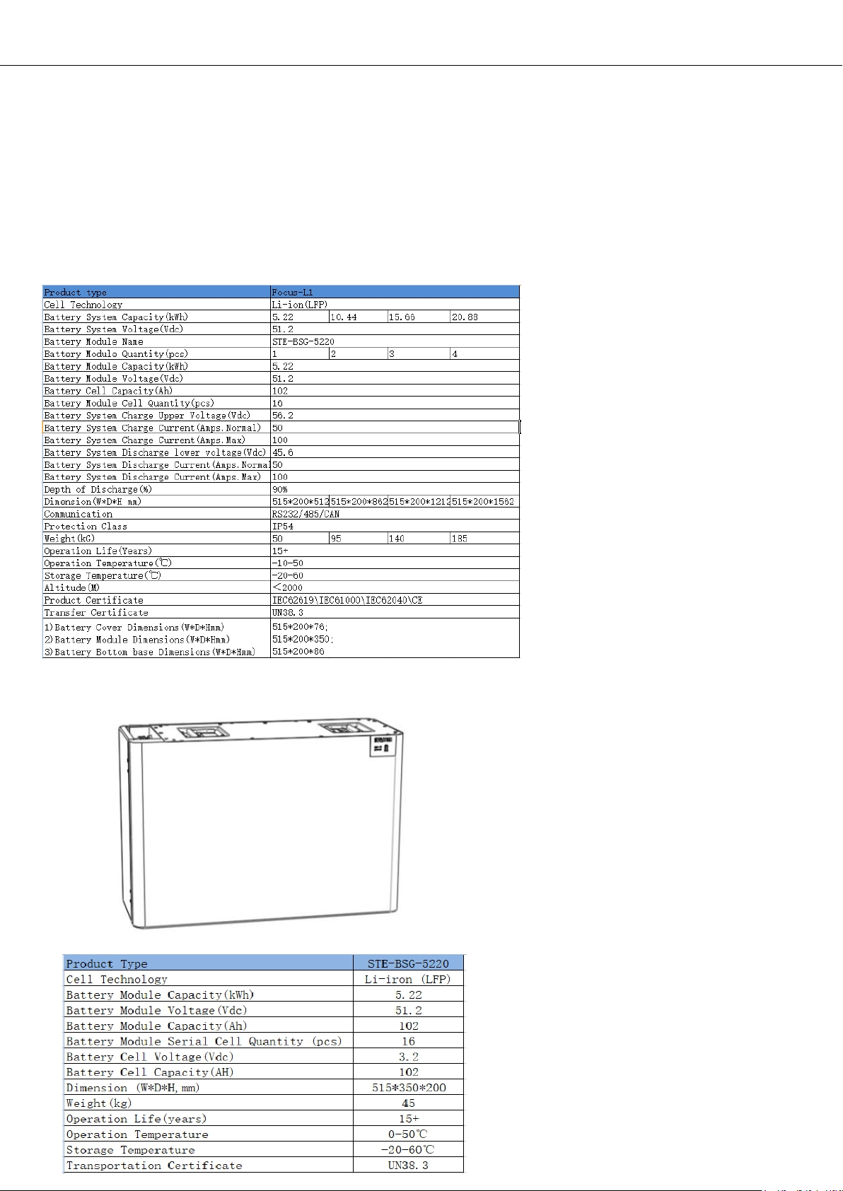
2.2 Specification
2.2.1 System Parameters
2.2.2 Battery Module (BPE-PD-5.22kWh)
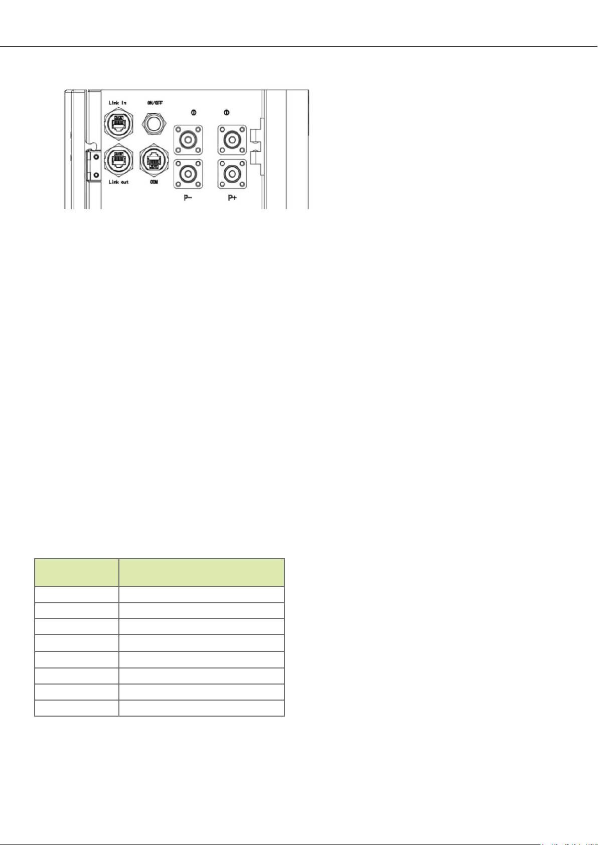
ON/OFF
Connection Area
1. ON
For a single BPE 5.22kWh battery, press and hold (for 5 seconds) the ON/OFF button. The Normal LED will light up and begin to
operate normally. The six green LED bars represent the battery's SOC.
For multiple BPE 5.22kWh batteries in parallel, press and hold (for 5 seconds) the ON/OFF button of MASTER battery (The battery
connected to the inverter with the communication cable). The Normal LED will light up and this battery will be assigned as the master
battery. The other batteries in the system will automatically be programmed and assign IDs as Slave batteries.
2. OFF
Press and hold the ON/OFF button on the Master battery (which is connected to the inverter) for more than 3s. The LED will flash on the
front panel and then release the button, the master battery will shut down as well as all of the slave batteries.
COM Port
CAN/RS485/RS232 Communication Terminal (RJ45 port):
For communicating with the inverter and ensuring your battery operates nominally; please connect the Comm Port on the master battery to
the BMS port on the inverter.
Use this table for creating your own communication cable with regular Cat5/6 and a crimping tool:
PIN Definition
Pin 1RS485-B (to PCS, reserved)
Pin 2RS485-A (to PCS, reserved)
Pin 3 GND_2
Pin 4CANH (toPCS)
Pin 5CANL (toPCS)
Pin 6 RS232_TX
Pin 7 RS232_RX
Pin 8 RS232_GND
Link in/Link out
Link in/Link out are used for the communication between battery packs. If you have more than one battery in your system, use a
communication cable to exit the Master Link Out port and connect it to the next Slave Link In port. Continue this pattern of Link in/Link out with
the additional batteries until the final battery just has a Link In cable running to it. (Reference diagrams on page 10.
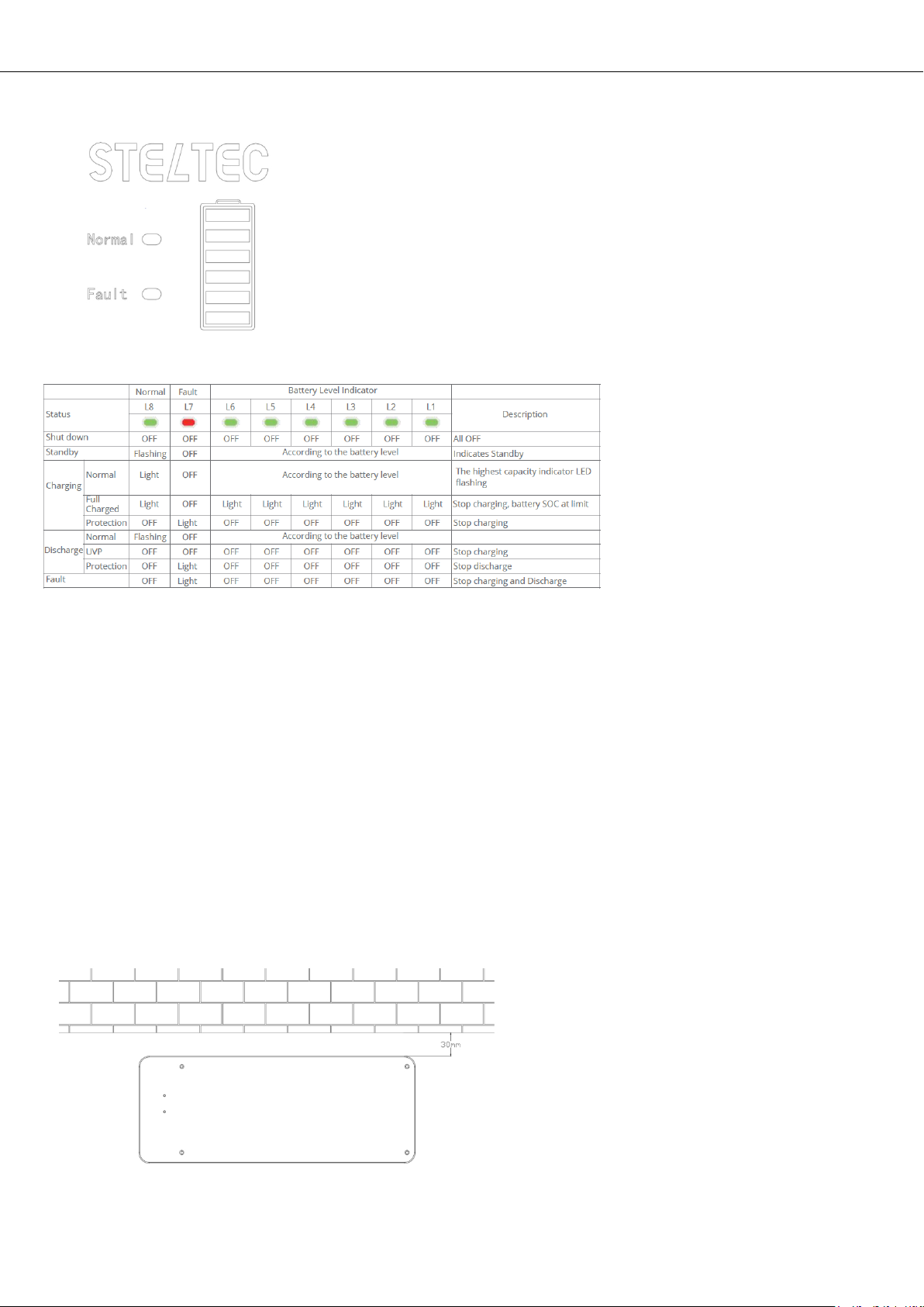
2.2.3 LED Indicator Definition
LED Indicators Instructions
3 Installation
3.1 Installation Requirements
It is recommended to install the battery in an indoor environment.
Do not expose the battery to direct sunlight.
Only mount battery on a stable floor surface.
Do not stack more than four BPE 5.22kWh on top of one another.
3.2 Installation
Step 1
Securely place the battery base near a wall, the distance between the base and the
wall should be 30mm. Ensure that the base is level before proceeding.

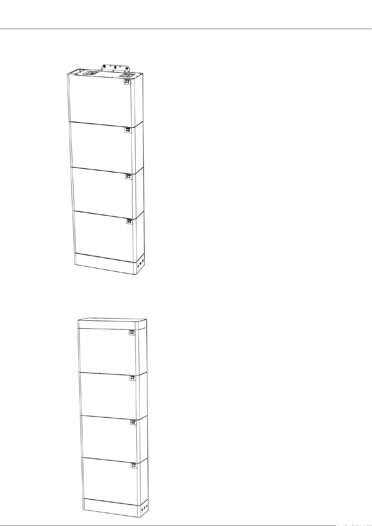
Step 2
Using the four included dowel pins, insert them into the corners by screwing them into the base with a screw driver. Next, place the battery
on top of the base; ensuring the battery securely sits on top of the dowels.
Step 3
If you're installing more than one 5.22kWh battery, insert four more dowel pins on top of the bottom battery.
Step 4
Place the second battery pack on top of the first pack. Repeat this process for all batteries as required.
Step 5
Fixed the battery with the wall using a L shaped metal parts and expansion bolts.
Step 6
Install the top cover onto the top most battery pack.
Step 7
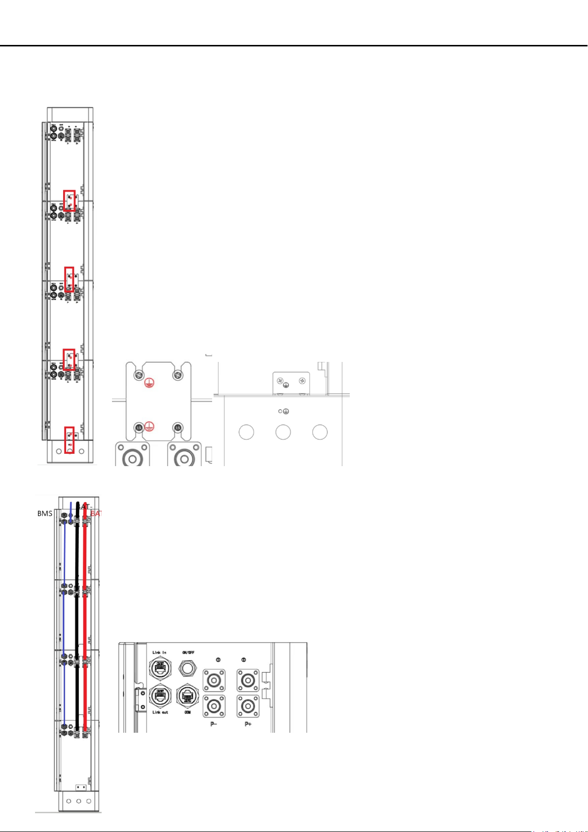
Ensure the batteries are all connected to the PE terminal by installing the included square brackets between each battery pack. The bottom
battery pack will attach to the base plate with an L shaped bracket.
Step 8
Connect all power and communication cables between the battery packs.
Connect the master battery pack positive and negative terminals (P+ and P-) to the inverter.
The blue cable is the communication for the batteries in parallel, this groes from Link in to Link out
Connect the COM port ot the BMS port on the inverter.
Danger: Do not reverse the polarity on any of the battery power cables.

4 Maintenance
Recharge Requirements During Storage
Battery should be stored in an environment with temperature range between -10°C ~+45°C and maintained regularly according to
following table with 0.5C (51A) current untill 40% SOC after a long period of storage.
Storage
Environment
Temperature
Relative Humidity of
Storage Environment Storage Time SOC
Below -10℃/Prohibited /
-10~25℃5%~70% ≤12 months 30%≤SOC≤60%
25~35℃5%~70% ≤6 months 30%≤SOC≤60%
35~45℃5%~70% ≤3 months 30%≤SOC≤60%
Above 45℃/Prohibited /
Table of contents


