SOLARFOCUS Vampair User manual

Installation manual for qualified personnel
Read carefully before operating.
DR-0072-EN / v41-202205
Air source heat pump vampair

1 About this manual 3
1.1 Limitation of liability 3
2 Safety information 3
3 Technical requirements 3
3.1 Warranty, guarantee, liability 3
3.1.1 Technical requirements for warranty and gua-
rantee claims 3
3.1.2 Conditions for claims 4
3.1.3 Claims rendered void 4
3.1.4 Limitation of liability 4
3.2 Standards, guidelines, regulations 5
3.3 Specifications for cooling mode 5
3.4 Installation location, installation position 5
3.5 Foundation for the heat pump 6
3.6 Line routing, connection 6
3.7 Heating system fill-up water 7
3.7.1 Avoiding scale buildup 7
3.7.2 Avoiding water-side corrosion 7
3.8 Information about the hydraulic connection 8
4 Product information 9
4.1 Product description 9
4.2 Functional components 10
4.3 Scope of delivery 11
4.4 Principle of operation 12
4.5 Innovative technologies 13
4.6 Dimensions 13
4.7 Accessories 13
4.8 Technical specifications 14
5 Prepare heat pump 17
5.1 Transport 17
5.2 Attach sealing tape 18
5.3 Dismantling the cover 18
5.4 Remove cladding 18
5.5 Remove transport lock 18
5.6 Connect the heat pump to the power supply
before commissioning 18
6 Install electric heating element 19
6.1 Important information 19
6.2 Heating element and components 19
6.3 Mount heating element 20
6.4 Connect the heating element 20
6.5 Fit the sensors (2x) in the heating element 21
7 Hydraulic connection 22
7.1 Make condensate drain, seal 22
7.2 Rinse the lines 22
7.3 Install the primary circuit circulation pump 22
7.4 Connect the primary circuit 23
7.4.1 Connection on the condenser 23
7.4.2 Cut insulating mat (only required for K 08 and K 10) 23
7.4.3 Primary circuit connection set 23
7.4.4 Fit temperature sensor T1 for condenser 26
7.4.5 Heat pump pipe 26
7.5 Pipe dimensions: Residual delivery height
information 27
7.5.1 vampair K 08, K 10 27
7.5.2 vampair K 12, K 15 27
8 Electrical connection 28
8.1 Access to terminal area 28
8.2 Terminal assignment 28
8.3 Seal the connection cable piping 29
8.4 Terminal area, electrical supply 30
8.5 Electrical connection plan 31
8.6 Connect ecomanager-touch control 32
8.6.1 Overview 32
8.6.2 Surface-mounted installation 32
8.6.3 Display power supply 32
8.6.4 Connect CAN bus 32
8.6.5 Connect RS485 bus 33
8.7 Connect electronic module D1 33
8.7.1 Terminal assignment - overview 33
8.7.2 Connection of the bus cable 33
8.7.3 Bus terminating resistor 34
8.7.4 Connect the primary circuit circulation pump 34
8.7.5 Connect the flow sensor 35
8.7.6 Heating circuit - switch externally (optional) 35
8.7.7 Connecting the mains power supply to the elec-
tronic module 35
8.7.8 Device address of the electronic module 36
8.7.9 Elec. fuses in the electronic module 36
8.8 Outside temperature sensor - position 36
8.9 Connecting the control to the internet 36
8.10 Smart Grid Ready 36
9 Initial commissioning 37
10 Foundation plan 38
10.1 Downward line connection 38
10.2 Line connection to the rear 41
10.3 Condensate drain 41
11 Flat roof set-up 42
12 Plant schematic 45
2 Installation manual vampair
Content

1 About this manual
1 About this manual
Language
The language of the original manual is German. Ver-
sions of this manual in all other languages are trans-
lations of the original.
Storage
Keep the manual for the entire service life of the pro-
duct and ready to hand. The manual must be passed
on to the new owner when the product is dis-
mantled/reused. If the manual is lost or destroyed,
request a new copy from the manufacturer.
Instructions and warnings
The instructions used in this manual are highlighted
with symbols and signal words. The signal word indi-
cates the level and nature of the danger.
iIndicates information for correct handling of
the product.
!CAUTION - Material damage is possible if
these instructions are not complied with.
DANGER - Failure to comply with this instruc-
tion poses a danger to people.
1.1 Limitation of liability
SOLARFOCUS GmbH assumes no liability for injury
or material damage resulting from:
–Failure to observe the instructions in this manual.
–Use of the product for any purpose other than for
its intended use.
–Deployment of unqualified personnel.
–Use of non-approved spare parts.
–Technical modification of the product by the sys-
tem operator.
Warranty, guarantee
See General Terms of Business and Delivery Con-
ditions of SOLARFOCUS GmbH.
Manufacturer
SOLARFOCUS GmbH
Werkstrasse 1, A-4451 St.Ulrich
Company register no. 281755x
Tel.: +43 7252 50 002-0, Fax: +43 7252 50 002-10
www.solarfocus.com
Service Hotline
–Email: [email protected]
2 Safety information
Installation and commissioning
–Heat pump may only be installed and put into
operation by certified qualified personnel
(SOLARFOCUS service technician or
SOLARFOCUS service partner).
–Install heat pump outdoors only.
–Never disconnect the heat pump from the power
supply (except electrical work). Otherwise risk of
frost damage
Maintenance and repair
–Have repairs done by qualified personnel only
Improper repairs can lead to risks for the user and
inefficient operating conditions.
–Use original spare parts only
Handling of refrigerant R410A
–The heat pump uses refrigerant R410A. Work on
the cooling circuit may be performed only by a
qualified refrigerant electrician.
–Wear suitable gloves and goggles when working
with refrigerant.
What to do in case of escaping refrigerant
–Escaping refrigerant[1] can cause frostbite if it tou-
ches the exit point. If refrigerant escapes do not
touch any components of the heat pump.
[1] Recognizable by oily residue, which is left when exiting.
–Avoid skin or eye contact with the refrigerant. In
case of skin or eye contact with the refrigerant, a
doctor should be consulted.
–Switch off heat pump, Contact qualified per-
sonnel.
3 Technical requirements
3.1 Warranty, guarantee, liability
Guarantee claims are valid as part of a heat pump
maintenance agreement.
3.1.1 Technical requirements for warranty
and guarantee claims
The following technical requirements must be obser-
ved as a precondition for a warranty and guarantee
claim.
Installation manual vampair 3

1 About this manual
Regular maintenance
–Have the heat pump serviced annually by qua-
lified personnel
Specifications for the heating system's fill-up/-
make-up water
–Check pH value: this must be in the range of
8.2 to 9.5
–Avoiding scale buildup > 7(=limescale on heat
exchanger surfaces):
–Take the water hardness into account
–Soften the fill-up water, or better: desalinate it.
–Avoiding water-side corrosion > 7(is triggered by
the oxygen in the water):
–Correct system planning, correct dimen-
sioning, take material combinations into
account.
–Repair leaks immediately.
–Expansion tank > 8(prevents air from being
drawn in when the system cools down): Cor-
rectly set the pressure, check it regularly.
–Existing underfloor heating: Take care with
old, diffusion-open plastic pipes > 9
3.1.2 Conditions for claims
For warranty and guarantee claims observe the fol-
lowing points:
–The warranty begins at the time at the time of han-
dover (delivery note, commissioning log).
–The guarantee period is calculated from the date
of initial commissioning (according to the control's
operating hour counter).
–The warranty periods are based on the relevant
regulations.
–We must be notified promptly and accurately of
any damage incurred, so that the cause can be
clarified.
–If the system has defects despite correct instal-
lation (in compliance with the technical docu-
mentation), we grant a warranty provided that the
system has been examined by the plant customer
service (commissioning log).
–The guarantee applies to technical, construction-
related faults and faults in the manufacture of the
system that prevent correct and problem-free
usage.
–We are not liable for parts that were not produced
by SOLARFOCUS. However, we are prepared to
transfer our existing claims against the producer
(relating to this defect) to the buyer.
–In fulfilling the warranty/guarantee services, we
shall cover only the assembly time and the mate-
rials used, but not any travel or accommodation
costs necessary for the fitters/engineers or any
return transport costs.
–SOLARFOCUS GmbH assumes no liability for
any consequential costs of damages.
–The repair and/or warranty replacement shall be
carried out on site or in the SOLARFOCUS fac-
tory at our discretion.
–The company SOLARFOCUS will determine whe-
ther such work requires a repair or whether the
parts are to be replaced free of charge.
3.1.3 Claims rendered void
The warranty and guarantee claims are rendered
void if one of the following points applies:
–Non-compliance with the technical requirements
> 3
–Damage during transport.
–Wilful damage.
–Damage due to force majeure (water, fire, etc.).
–Non-observance of information in the planning,
installation and operation manual.
–Insufficient energy or water, fault in the hydrau-
lics.
–Incorrect operation, failure to perform main-
tenance and cleaning as prescribed.
–Commissioning and maintenance carried out by
non-certified companies.
–Undocumented commissioning (no com-
missioning log) and/or maintenance (main-
tenance log).
–It is almost impossible to produce flawless pain-
ted parts; for this reason, slight defects that do not
adversely affect proper use shall not be deemed
as grounds for complaint.
–No claims can be ß under the warranty if unaut-
horised intervention (or action that has not been
explicitly approved by us the manufacturer) has
been carried out. In addition, the goods must be
paid for within the specified payment timeframe.
3.1.4 Limitation of liability
SOLARFOCUS GmbH assumes no liability for injury
or material damage resulting from:
–Failure to observe the instructions in this manual.
–Use of the product for any purpose other than for
its intended use.
–Deployment of unqualified personnel.
–Use of non-approved spare parts.
–Technical modification of the product by the sys-
tem operator.
4 Installation manual vampair

1 About this manual
3.2 Standards, guidelines, regulations
The following bodies of regulations must be con-
sidered and adhered to during planning, installation
and operation of the heating system:
Standards for heat pump systems
–EN 378-2 - Refrigerating systems and heat
pumps - Safety and environmental requirements
–ISO 6529 - Protective clothing - Protection
against chemicals - Determination of resistance of
protective clothing materials to permeation by
liquids and gases
–EN 60335-1 - Household and similar electrical
appliances - Safety - Part1: General requi-
rements
–EN 60335-2-40 - Household and similar electrical
appliances - Safety
–EN 61000-3-3 - Electromagnetic compatibility
(EMC) - Part 3-3: Limits - Limitation of voltage
changes ≤16 A per phase
–EN 61000-3-11 - Electromagnetic compatibility
(EMC) - Part 3-11: Limits - Limitation of voltage
changes ≤75 A per phase
–EN 55014 - Electromagnetic compatibility. Requi-
rements for household appliances, electric tools
and similar apparatus.
–DIN 8901 - Refrigerating systems and heat
pumps with flammable refrigerants of group L3
(Germany)
–DGV (SR 819.121) - Pressure equipment safety
ordinance (Switzerland)
–DBV (SR 819.122) - Pressure vessel ordinance
(Switzerland)
–SN EN 378 - Refrigerating systems and heat
pumps - Safety and environmental requirements
(Switzerland)
Standards for heating water
–ÖNORMH 5195-1 - Heat transfer media for buil-
ding services systems, Part 1: Preventing
damage from corrosion and scale formation in clo-
sed hot water heating systems (Austria)
–VDI 2035 - Prevention of damage in hot water
heating systems (Germany)
–SWKI BT 102-01 - Water quality for building sys-
tems (Switzerland)
–UNI 8065 (Italy)
3.3 Specifications for cooling mode
!CAUTION - Observe the following points
when using the heat pump for room cooling.
Failure to comply poses a risk of damage due
to moisture in building elements (due to con-
densation).
–If the temperature falls below the dew point tem-
perature in the cooling system (lines, cooling sur-
face, buffer tank), water precipitates out of the air.
Condensation forms on the cooled system parts.
–The system must have insulation suitable for coo-
ling (=diffusion-resistant).
–Take particular care when using carbon steel -
risk of external corrosion
–Use room control with humidity sensor, e.g.
SOLARFOCUS Art. 26610. This regulates the
cooling flow temperature, taking the room tem-
perature and room humidity into account, and pre-
vents the temperature falling below the dew point.
–If room control with humidity sensor is not used:
Position the dew-point sensor on the lines.
–For further information, see Heat pump planning
document, DR-0302
–Standards
–ISO 12241 - Thermal insulation for building equipment
and industrial installations - Calculation rules
–DIN 4140 - Insulation work on industrial installations and
building equipment - Execution of thermal and cold insu-
lations
3.4 Installation location, installation posi-
tion
–Outdoor installation only
–The ground must be seepable (due to condensate
discharge > 6) and local regulations and con-
ditions must be observed.
–The heat pump is weatherproof and requires no
additional protective measures (roofing, ...).
Exception: In the event of a risk of roof avalan-
ches, mechanical protection for the heat pump
must be provided, e.g. protective roof).
–The air flow through the evaporator must not be
impaired on the air intake and exhaust side (e.g.
by shrubs, walls,...).
–Do not install the heat pump with the air outlet
side against the main wind direction. Preferred
installation is on a wall, with minimum distance,
see foundation plan > 38.
–Take noise development into consideration (do
not place in front of the bedroom window, next to
the terrace, near neighbours ...).
–Ensure free accessibility (e.g. for service work).
–Installation in a sink is not permitted (lack of air
exchange due to sinking, cold air).
–The sucked air must not be contain ammonia.
The use of exhaust air from animal stables is the-
refore not permitted.
–When using heat pumps near the sea, the high
salt content of the air can lead to increased cor-
rosion (invalidation of warranty if ignored). The
use of heat pumps is harmless from a distance of
12 km to the sea.
Installation manual vampair 5

1 About this manual
3.5 Foundation for the heat pump
Requirements for the foundation
The foundation for the heat pump must fulfil the fol-
lowing requirements:
–Horizontal orientation
–Weatherproof, frost-proof
–Sufficient load-bearing capacity
–Seals the heat pump at the bottom (prevents
sound output; prevents the ingress of rodents)
–Vibration-resistant
Concrete foundation
–In the case of a primary circuit connection from
below > 24 provide the required feed-throughs in
the concrete foundation.
–Position the heat pump directly on the concrete
foundation (affix the supplied sealing tape to the
underside of the heat pump base > 18)
–Screwing the heat pump to the concrete foun-
dation is not required
–Insulate the heat pump laterally with moisture-resi-
stant XPS panels (do not use EPS panels)
–Optional: For easy preparation of the concrete
foundation see article Insulating brick for foun-
dation (Art. No. 25350, Instructions DR-0132).
This XPS-shaped block allows fast, convenient
formation of the foundation, including the precise
placement of the heat pump pipe.
Condensate discharge
iWhen defrosting the evaporator, condensate
accumulation of up to 50 litres per 24 h is pos-
sible, even over a longer period. This quantity
of fluid must be reliably discharged.
2 methods of discharging:
Drain into the ground: If sufficient water-permeable
earth layers are present, it is sufficient to lay the drain
pipe in gravel fill to a depth of 90 cm (frost-free) > 38 ff
!CAUTION - When placing the heat pump
close to the building, it must be ensured that
the condensation does not damage the buil-
ding.
!CAUTION - Use a perforated version ("drai-
nage pipe") as on-site drain pipe > 22.
Discharge into the sewage system: Outdoors is pos-
sible, or to frost-free depth indoors (basement, ...) is
possible. In both cases provide sufficient slope and
trap (siphon) If a part of the drainage hose can not be
laid frost-free, it must be heated by a heating cable.
►Connect the condensate drain line > 22
Permissible installation types
–On continuous concrete foundation
–On concrete flat roof
Impermissible installation types
–On pad or strip foundation
–On structures that can oscillate (e.g. supporting
frames made of wood or metal, terraces, light-
weight ceilings)
–On wall/facade (e.g. with metal support bracket)
3.6 Line routing, connection
Protect lines against frost
–Lay the heat pump pipe (with heating flow and
return line) at frost-free depth.
–Lay the outlet of the condensate drain hose > 6 to
frost-free depth.
Observe heat pump pipe connection
Abb. 2-1
see foundation plan > 38:
6 Installation manual vampair

1 About this manual
3.7 Heating system fill-up water
In regard to the fill-up water quality, two key points
must be observed (in accordance with Guideline
VDI2035):
–Avoiding scale buildup (limescale)
–Avoiding water-side corrosion (caused by oxygen
in the heating water)
The lowest possible rate of corrosion of the installed
metal materials is primarily achieved when the circula-
tion water is in the correct pH range (8.2 to 9.5), while
at the same time, the electrical conductivity is as low
as possible (50 to 100 µS/cm).
3.7.1 Avoiding scale buildup
What is scale buildup?
Scale buildup is the formation of firmly adhering depo-
sits on water-contacting walls of hot water heating
systems. This can subsequently lead to damage
(stress cracks in metal, leaks).
Causes of scale buildup
The cause of scaling is the presence of calcium carbo-
nate in the water.
The following calculation/table determines the total
permitted hardness of the fill-up water. If the value is
exceeded, the fill-up water must be treated, e.g. sof-
tened.
Calculation of the total permitted hardness of the
fill-up water
To use the table, the specific system volume for the
system must be determined:
System volume divided by total heat output results in
the specific system volume
1166 litres / 25 kW =46.64 l/kW specific system
volume
Table:Total permitted hardness of the fill-up water
Total heat
output
Specific system volume (VDI 2035)
<20
l/kW
≥ 20 <50
l/kW
≥ 50
l/kW
< 50 kW ≤ 16.8°dH ≤ 11.2°dH < 0.11°dH
50 - 200 kW ≤ 11.2°dH ≤ 8.4°dH < 0.11°dH
20 - 600 kW ≤ 8.4°dH < 0.11°dH < 0.11°dH
> 600 kW < 0.11°dH < 0.11°dH < 0.11°dH
In our example: if the total hardness of the fill-up
water is more than 11.2dH, then the fill-up water
must be treated.
3.7.2 Avoiding water-side corrosion
Corrosion is usually triggered by the available oxygen
in the water. This value can be brought into a safe
range with proper planning, design, installation and
maintenance of the heating system. A constant input
of oxygen should be avoided.
Important in this regard:
–Expansion tank > 8: Air must be prevented from
being drawn in when the heating system is coo-
ling down. Ensure:
–Correct planning and implementation of the
expansion tank.
–Regular check of the system pressure, expan-
sion tank pre-pressure.
–Immediate repair of leaks in the heating system.
–In the case of older underfloor heating, ensure
pipes are diffusion resistant > 9
Check the pH of the fill-up water
–The pH value must be between 8.2 and 9.5.
–If this pH value does not self adjust after a week of
operation, it must be raised by adding 10 g/m³ tri-
sodium phosphate (Na3PO4) or 5 g/m³ sodium
hydroxide (NaOH). Allow 2 to 4 weeks of ope-
ration before further corrections.
–Exception: If aluminium materials are used in the
heating system, a pH from 8.2 to 8.5 must be met
(pH> 8.5 increased corrosion tendency).
Resistance of materials to water constituents
Irrespective of legal requirements, the following limit
values in the heating water used for different mate-
rials may not be exceeded or fallen below in order to
ensure safe operation of the heat pump. For this, an
analysis of the water must be carried out before com-
missioning.
If the pre-commissioning water analysis for one indi-
cator shows a "-" or an "o" for two indicators, treat-
ment of fill and make-up water is required.
Limits for the quality of the heating water:
Substance in
water
Concentration
mg/l or ppm
Stainless
steel Copper
Alkalinity
(HCO3-)
<70 + o
70-300 + +
>300 + o/+
Sulphate
(SO42-)
<70 + +
70-300 + o / -
>300 o -
HCO3-/ SO4->1.0 + +
<1.0 + o / -
Installation manual vampair 7

1 About this manual
Substance in
water
Concentration
mg/l or ppm
Stainless
steel Copper
Electrical con-
ductivity
<10 μS/cm + o
10-500 μS/cm + +
>500 μS/cm + o
pH value] <6.0 o o
6.0-7.5 o/+ o
7.5-9.0 + +
>9.0 + o
Ammonia
(NH4+)
<2 + +
2-20 + o
>20 + -
Chloride (Cl-) <300 + +
>300 o o / +
Free chlorine
(Cl2)
<1 + +
1-5 + o
>5 o/+ o / -
Hydrogen sul-
phide (H2S)
<0.05 + +
>0.05 + o / -
CO2<5 + +
5-20 + o
>20 + -
Total hardness
(°dH)
4.0-8.5 + +
Nitrate (NO3) <100 + +
>100 + o
Iron (Fe) <0.2 + +
>0.2 + o
Aluminium (Al) <0.2 + +
>0.2 + o
Manganese
(Mn)
<0.1 + +
>0.1 + o
The water quality should be rechecked after 4 to 6
weeks as it may change due to chemical reactions
during the first few weeks of operation.
Electrical conductivity
The probability of corrosion usually decreases with
decreasing electrical conductivity of the heating
water.
Low salt operation - filling with demineralised
water, see VDI 2035 sheet 2.
Low salt
Electrical conductivity at 25°C < 100 µS/cm
In the case of low-salt operation, feeding with non-
demineralised water can have a significant effect on
the pH value and push it into a critical range.
►Check the pH value regularly.
3.8 Information about the hydraulic
connection
Pressure equalisation through expansion tank
–The expansion tank prevents air from being
drawn in when the system cools down (issue: oxy-
gen input, heating system's fill-up water > 7)
–Dimension the expansion tank with a capacity of
12% of the total hydraulic system volume.
–Secure the expansion tank against shut-off. To do
this, either use the shut-off options on the way to
the expansion tank as cap valves, or unscrew the
hand lever (handwheel) and attach it to the expan-
sion tank with the wire in a clearly visible position.
–Installation of an expansion tank or a pressure
maintenance system is essential. Use of open
expansion tanks is not permitted.
–The pressure in the heating system (can be read
off the manometer) and the set pre-pressure in
the expansion tank must be checked regularly.
Install the temperature sensor in the immersion
sleeves
–Install the flow and return temperature sensor of
the heating system in the immersion sleeves.
–Exceptions are only permitted in the case of
installation in copper or carbon steel lines. In this
case, correct insulation of the sensor must be
ensured.
Installing the dirt and sludge separator
–Installation of a filter (<25μm) is a condition for
guarantee and warranty claims, e.g. use
SOLARFOCUS dirt and sludge separator. This
prevents the ingress of particles into the plate
heat exchanger (condenser).
Return hose version (structure borne sound
decoupling)
–To prevent structure-borne sound transmission
(and thereby resulting noise), a minimum length
of 30 cm and arched line routing must be obser-
ved for the primary circuit return hose; see infor-
mation on design > 23
8 Installation manual vampair

4 Product information
Caution with (older) diffusion-open plastic pipes,
e.g. existing underfloor heating
–In the case of older underfloor heating, the dif-
fusion-open plastic pipes can result in increased
oxygen input in the heating system. This has a cor-
rosion-inducing effect on the heating system com-
ponents (see: Avoiding water-side corrosion > 7).
–In this case, the system must be separated
(through installation of a heat exchanger).
–Newer plastic pipes (since around the mid 1980s)
are diffusion resistant in line with DIN 4726.
4 Product information
4.1 Product description
The air source heat pump vampair is a compact air
source heat pump for outdoor installation. As stan-
dard, it has a cooling function which extracts heat
from the heating surfaces in the living area (under-
floor heating, wall heating) and cools it by reversing
the circulation.
vampair works with inverter technology and Enhan-
ced Vaporized Injection > 13. The defrosting of the
evaporator is done by circulation reversal.
Rear side (intake grille)
Abb. 2-2
Front side (soundproofing slats)
Abb. 2-30:View K 08, K 10
Installation manual vampair 9
1 About this manual
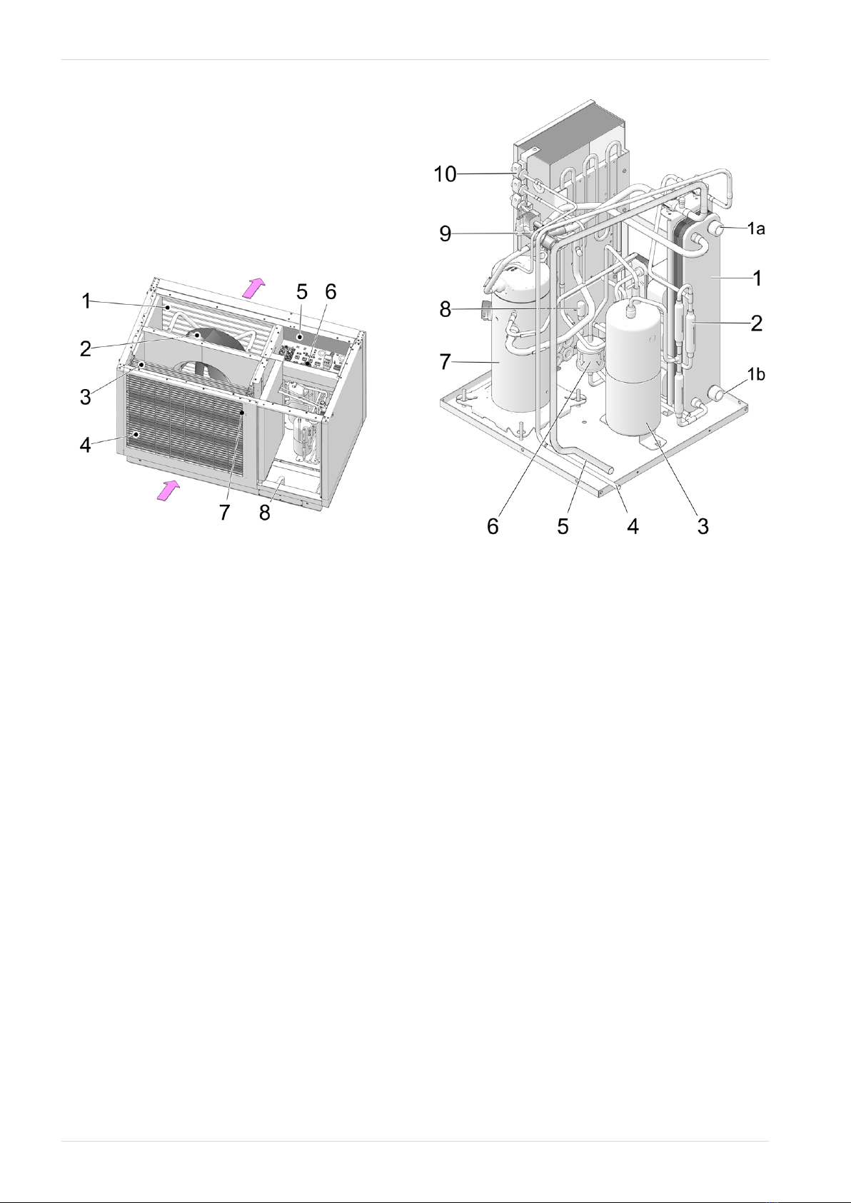
4.2 Functional components
vampair K 08 and K10
The fan 2sucks the ambient air (outside air) through
the evaporator 3and blows it out through the sound-
proofing slats 1.
The condensate formed during defrosting of the eva-
porator is discharged through the outlet 8.
Abb. 2-4
1 Soundproofing slats
2 Fan
3 Evaporators
4 Intake grille
5 Terminal area (electrical connection terminals)
> 30
6 Overtemperature reset (OTR)[1] > 19
7 Outside temperature sensor > 36
8 Condensate drain > 6
[1]Only when using electric heating element (optional accessory)
Components cooling circuit (without evaporator)
Abb. 2-5:View from behind - left
1 Condenser (plate heat exchanger)
1a Primary circuit flow outlet
1b Primary circuit return inlet
2 Non-return valve
3 Liquid collector
4 Fluid line to evaporator
5 Suction gas line from evaporator
6 Filter dryer
7 Scroll compressor
8 Expansion valve
9 Four-way switchover valve
10 Pressure sensors
10 Installation manual vampair

1 About this manual
Abb. 2-6: View from the front - left
1 Schrader valve
2 Shut-off valve
3 High pressure switch
4 Connection box
5 Economizer heat exchanger
6 Inverter chokes
DANGER - Do not operate or open Schrader
valves 1and shut-off valves 2. Risk of injury
due to refrigerant leakage.
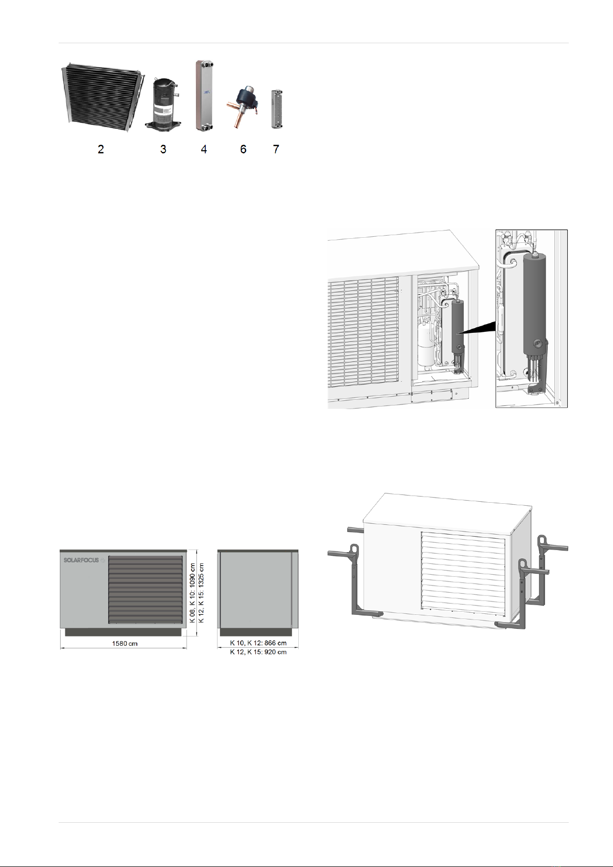
4.3 Scope of delivery
Accessory for vampair K08 and K10
No Qty. Art. no. Designation
1 1 69803-
1002
ecomanager-touch 7" control
panel
2 1 69810-
1000
Universal module (electronic
module)
3 1 61532 Heating pump "HE" Yonos Para
RS 25/7.5 iPWM-180
4 1 9390 Connection set "Optibal pump
ball valve" KWP10
5 1 54920 Plastic spiral hose 22 x 3.5 mm f.
KWP
6 1 61532-
ISO
Insulation for 61532 Wilo Yonos
Para 25/7.5 iPWM
7 1 69034-
1000
Power supply 230V-AC/24V-DC
primary
8 1 69035-
1000
Housing for display, surface
mounted
9 3 69095-
1000
Tank sensor PT1000 PVC - 5 m
10 2 69645 Immersion sleeve 1/2" x50 / 7
mm
11 1 69824 Sticker set ecomanager
12 1 7936 Packaging 700x350x300mm
13 1 9906 Immersion sleeve brass length:
140 cm
14 1 9345 Screw set electronic modules II
15 1 69336 Hose clamp 25 - 40 mm gal-
vanised steel
16 1 54947 Compriband-N15x15 mm SKVK
17 8 54949 Cover plug 8.5/12
18 1 DR-
0072
Installation manual
19 1 DR-
0086
Operation manual
Installation manual vampair 11

1 About this manual
Accessory for vampair K12 and K15
No Qty. Art. no. Designation
1 1 9345 Screw set electronic module II
2 1 9906 Immersion sleeve brass length:
140 cm
3 1 16401 Electronic volume flow sensor 5-
85 l/min
4 2 54787 Transition piece for volume flow
sensor KWP15
5 1 54920 Plastic spiral hose 22 x 3.5 mm f.
KWP, condensate drain hose
6 1 54947 Compriband-N15x15 mm SKVK
7 8 54949 Cover plug 8.5/12
8 1 54976 Pump ball valve with shut-off
valve DN32 Rp5/4" x G 2"
9 1 54977 Pump ball valve without shut-off
valve DN32 Rp5/4" x G 2"
10 2 54978 Insulation for pump ball valve DN
32
11 2 55035 Seal EPDM SH 70 2" KWP15
12 1 55051 Union nut G 2", set of 2 pcs
13 1 61526 Heating pump "HE" Stratos Para
30/1-8 T2-180
14 1 69034-
1000
Power supply 230V-AC/24V-DC
primary
15 1 69035-
1000
Housing for display, surface
mounted
16 2 69095-
1000
Tank sensor PT1000 PVC - 5 m
17 1 69803-
1002
ecomanager-touch 7" control
panel
18 1 69810-
1000
Universal module (electronic
module)
19 1 69336 Hose clamp 25 - 40 mm gal-
vanised steel
20 1 69645 Immersion sleeve 1/2"x50 / 7 mm
21 1 69824 Sticker set ecomanager
22 1 DR-
0072
Installation manual
23 1 DR-
0086
Operation manual
The parts in both accessory sets are packed in the
heat pump when delivered; for removal dismantle
cladding, see Prepare heat pump > 17
Not included in the scope of delivery: Heat pump pipe
> 26; electric heating element > 13; lifting aid > 13; pri-
mary circuit connection set > 23
4.4 Principle of operation
The function of a heat pump is similar to that of a ref-
rigerator from a technical standpoint, but reversed.
The refrigerator extracts heat from the food to be coo-
led and releases it to the room air.
The heat pump vampair withdraws heat from the out-
side air and delivers it to the heating system.
Four processes are decisive in the cooling circuit of
the heat pump:
Evaporation
The evaporator (2) takes the circulating refrigerant
energy from air and changes its state from liquid to
gaseous.
Compression
In an electrically driven scroll compressor 3, the
gaseous refrigerant is heated by compression.
Liquefaction (condensation)
The absorbed thermal energy is delivered to the hea-
ting system. The gaseous refrigerant is cooled in the
condenser (plate heat exchanger) and liquefied again
4.
Expansion
The pressure of the liquid refrigerant is reduced, resul-
ting in partial evaporation. The result is a mixture of
liquid and gaseous refrigerant (= wet steam). The ref-
rigerant cools down.
1 Energy from outside air
2 Evaporators
3 Scroll compressor
4 Condenser
5 Discharge of heating heat
6 Expansion valve
7 Economizer-heat exchanger (for Enhanced
Vaporized Injection)
8 Enhanced Vaporized Injection
12 Installation manual vampair
1 About this manual
4.5 Innovative technologies
Inverter technology
The scroll compressor not only works in on/off mode,
but is operated with output control (modulating, accor-
ding to the current power requirement).
Advantage:
–Precise power adjustment.
–Increased efficiency through reduced pulsing.
–Quieter operation on average due to reduced
speed in the partial load range.
–Reduction of the power of secondary drives (fan,
primary circuit pump)
Enhanced Vaporized Injection
In the scroll compressor, wet steam is injected from
the economizer heat exchanger for cooling.
Enhanced Vaporized Injection increases efficiency,
while the power requirement is reduced at the same
time. Thus higher flow temperatures and higher
heating output (especially at low outside tempe-
ratures) are possible. The compression temperature
decreases, increasing the life expectancy of the
compressor.
4.6 Dimensions
4.7 Accessories
Electric heating element
–Optional accessories, Art. 25200
–Depending on the type of connection, the electric
heating element achieves an output of 3, 6 or 9
kW.
–Mounting on the flow (primary circuit).
–An overtemperature reset (OTR) > 19 and
contactor are pre-installed in the heat pump as
standard.
►Install electric heating element > 19
Abb. 2-7: Electric heating element mounted
Lifting aid
–Optional accessories, Art. 25300
–To carry, lift and move the heat pump
–4-piece
Abb. 2-8
Installation manual vampair 13

4.8 Technical specifications
vampair K 08 K 10 K 12 K 15
Recommended building heat load [1] [kW] 5.7 7.8 9.4 15
SCOP, moderate climate W35/W55 (EN 14825) 4.2/3.4 4.73/3.8 4.4/3.4 4.95/3.85
ηs seasonal room heating energy efficiency, moderate cli-
mate 35 / 55 °C [%] 165/133 186/149 173/133 195/151
Energy data
Energy efficiency class, moderate climate W35/W55 A++ /
A++ A++ / A++ A++ /
A++ A++ / A++
Energy efficiency class incl. control, moderate climate
W35/W55
A++ /
A++
A+++ /
A+++
A++ /
A++
A+++ /
A+++
Heat output
Max. heat output at A -7/W35 [kW] 5.7 7.5 10.0 14.7
Max. heat output at A -10/W35 [kW] 5.3 7.0 9.4 13.7
Heat output at A10/W35 [kW] 4.57 6.09 6.46 11.56
Heat output at A7/W35 (EN 14511) @5K [kW] 4.29 6.19 6.06 11.98
Heat output at A2/W35 [kW] 3.94 5.47 7.31 9.46
Heat output at A -7/W35 [kW] 5.68 5.83 10.08 11.26
Heat output at A7/W55 [kW] 4.41 6.36 6.0 11.58
Cooling capacity
Max. cooling capacity A35 / W18 [kW] 5 6 10 15
Max. cooling capacity A35/W7 [2] [kW] 4 5 8 13
Power consumption
Fan power consumption max. [W] 35 81 60 170
Power consumption at A10/W35 [kW] 0.86 1.13 1.2 2.1
Power consumption at A7/W35 (EN14511) [kW] 0.88 1.24 1.2 2.4
Power consumption at A2/W35 [kW] 0.95 1.25 1.7 2.1
Power consumption at A -7/W35 [kW] 1.8 1.66 3.15 3.29
Power consumption at A7/W55 [kW] 1.4 1.92 1.8 3.41
Coefficients of Performance
Coefficient of Performance COP at A10/W35 5.3 5.4 5.4 5.5
Coefficient of Performance COP at A7/W35 (EN14511) 4.83 4.97 5.0 5.0
Coefficient of Performance COP at A2/W35 4.15 4.37 4.2 4.49
Coefficient of Performance COP at A -7/W35 3.16 3.51 3.2 3.42
Coefficient of Performance COP at A7/W55 3.17 3.32 3.3 3.4
Sound data
Sound power level (EN 12102) [dB(A)] 45 50 48 55.7
Sound pressure level at 5 m distance, in free field Silent Mode [dB(A)] 18 21.7 22 22
Sound pressure level at 3 m distance, set up in the open
Silent Mode [dB(A)] 25.5 29.2 29.5 29.5
Sound pressure level at 5 m distance, set up in the open
Silent Mode [dB(A)] 21 24.7 25 25
Sound pressure level at 4 m distance, set up against a wall
Silent Mode [dB(A)] 26 29.7 30 30
Sound power level max. (day/silent) [dB(A)/
dB(A)] 46 / 43 54 / 47 50 / 47 63 / 47
Cooling circuit
Refrigerant
Refrigerant fill level [kg] R410A R410A R410A R410A
1 About this manual
14 Installation manual vampair
1 About this manual
Installation manual vampair 15
vampair K 08 K 10 K 12 K 15
GWP (according to EN378), kg CO2 equivalent per kg [kg/kg] 4.78 4.78 6.7 6.7
CO2 equivalent [t] 9.98 9.98 13.99 13.99
Condenser material 1.4401/Cu
Operating limits
Operating limit outside air min. [°C] -22
Operating limit outside air max. [°C] 35°C
Operating limit heat-side air min. [°C] 26°C
Operating limit heat-side air max. [°C] 65°C
Operating limit outside air at W60 [°C] -22°C
Operating limit outside air at W65 [°C] -5
Water hardness [°dH] 4 – 8.5
pH value 7.5 – 9
Conductivity [μS/cm] 10 – 500
Free chlorine [mg/l] < 0.5
Electrical data
Protection type (IP) IP X4
- 1-phase version (K 08.1, K 10.1, K 12.1, K 15.1)
Number of compressors 1 -
Compressor connection ~230V, 50 Hz,
5,5kW -
Control connection [A] ~230 V 50Hz -
Compressor fuse [A] 25 -
Control fuse [A] 10 -
Starting current [A] 15 -
- 3-phase version (K 08.3, K 10.3, K 12.3, K 15.3)
Number of compressors 1
Compressor connection ~400V, 50 Hz;
5,5kW
~400V, 50 Hz;
8kW
Control connection ~230 V, 50Hz
Auxiliary heating power consumption max. [kW] 3 / 6 / 9
Auxiliary heating connection ~400V, 50Hz
Compressor fuse [A] 13 16
Control fuse [A] 10 10
Auxiliary heating fuse [A] 13 13
Starting current [A] 6.5 8
Dimensions
Height [mm] 1090 1325
Width [mm] 1580 1580
Depth [mm] 870 920
Weight
Weight (including packaging) [kg] 348
373
401
426
Connections
Connection for heating flow/return ["] G 5/4" OT
Flow rates
Air flow rate [m³/h] 1300 2900 2000 4400
Heating volume flow rate min. [l/h] 520 520 800 800
Heating volume flow rate min. for defrosting and com-
missioning[3] [l/h] 1560 1560 2500 2500
Heating volume flow rate, at A7/W35 and 5 K [l/h] 1080 1080 2080 2080

[1] At standard outside temperature -14°C, heating limit temperature 15°C, flow 35°C/return 28°C, taking into account 5% share of peak load
heat generator (without domestic hot water)
[2] With extension set low-temperature cooling
[3] If this volume flow is not achieved via the heat pump plate heat exchanger (= heating volume flow), commissioning is not possible.
1 About this manual
16 Installation manual vampair
5 Prepare heat pump
5 Prepare heat pump
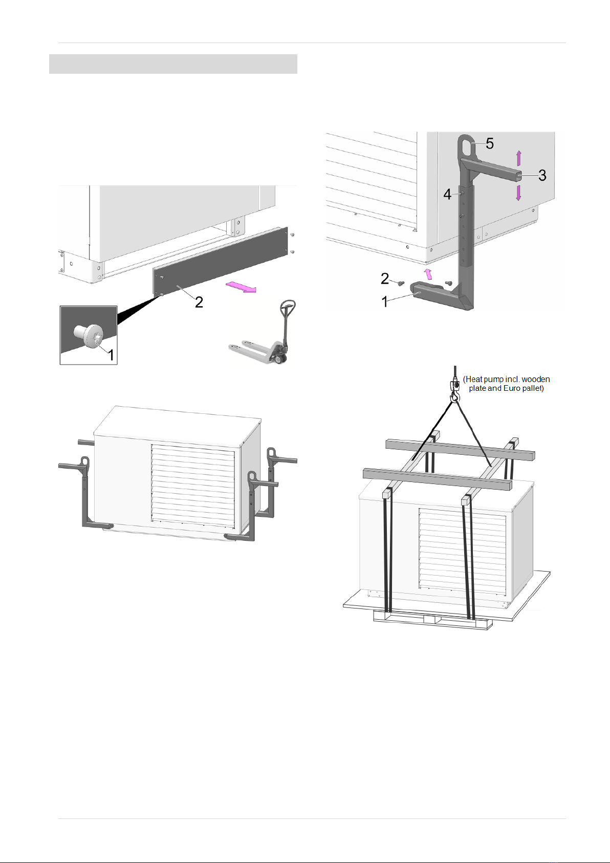
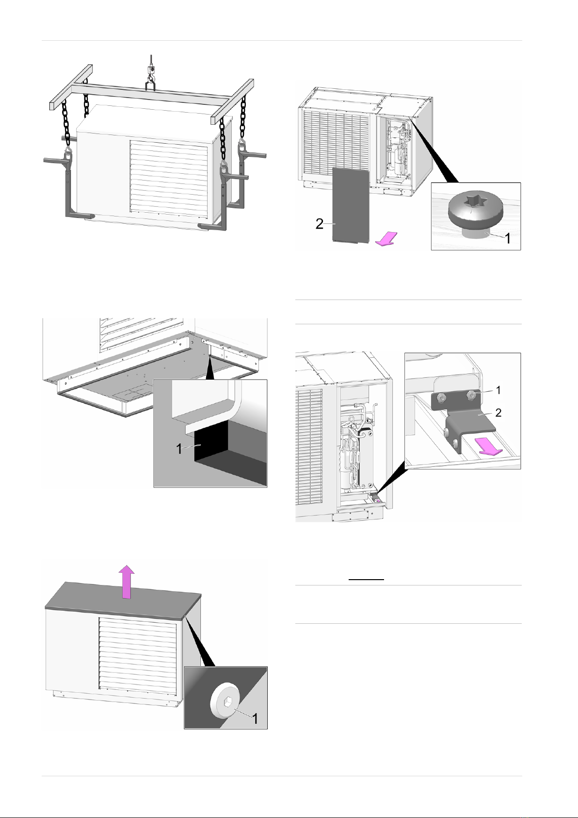
5.1 Transport
Option 1: Transport with a lift truck
►Loosen the 4 sheet metal screws (TX25) 1and
remove both covers 2.
►Carefully insert the lift truck (the pipe bend for the
condensate drain is on the left side).
Abb. 2-9
Option 2: Lifting/moving with the lifting aid
Abb. 2-10: Lifting aid, 4-part
►Mount the bracket 1with two screws 2on the
base of the heat pump.
The support angle 3is adjustable by repo-
sitioning the screws 4to a different height.
The tab 5is used for attaching a hoist, e.g. for
transport by crane.
Abb. 2-11:Lifting aid
Option 3: Lifting with a crane
Abb. 2-12: Crane transport with Euro pallet (condition at delivery)
Installation manual vampair 17
5 Prepare heat pump
Abb. 2-13: Crane transport with lifting aid
5.2 Attach sealing tape
►For optimum thermal and acoustic sealing, affix
the enclosed sealing tape 1over the underside of
the base (over the entire base circumference).
Abb. 2-14
5.3 Dismantling the cover
►Loosen the cylinder head screws TX25 1and
remove the covers.
Abb. 2-15
5.4 Remove cladding
►Loosen the 6 bolts (TX25 ) 1, remove cladding 2.
Abb. 2-16
5.5 Remove transport lock
iOnly required for K 12 and K 15
►Loosen 4 pcs. screws 1and permanently remove
transport lock 2.
Abb. 2-17
5.6 Connect the heat pump to the power
supply before commissioning
iConnect the heat pump to the power sup-
ply at least 12 hours before com-
missioning.
The oil sump heating then starts the heating process,
this pre-heating ensures smooth commissioning of
the heat pump.
18 Installation manual vampair

6 Install electric heating element
6 Install electric heating element
6.1 Important information
!CAUTION
–Follow the following installation steps
exactly.
–If errors are made during installation,
the electric heating element's safety
devices will be ineffective.
–The risk of subsequent damage is very
high.
–The electric heating element, which is available
as an optional accessory[1], is connected to the
primary circuit flow of the condenser (heat exchan-
ger).
–A contactor and overtemperature reset (OTR) are
already preinstalled in the heat pump. CAUTION:
The capillary tube sensor of the overtemperature
reset must be positioned in the heating element
on site > 21
–The overtemperature reset protects the heating
element from overheating (by interrupting the
power supply, e.g. during dry running).
–A mounting bracket is enclosed with the heating
element.
[1] The heating element is only available for the three-phase ver-
sion of the vampair, i.e. K 08.3, K 10.3, ...
!CAUTION - Protect the electrical terminal
area ofthe heat pump against moisture (e.g.
precipitation) during installation work.
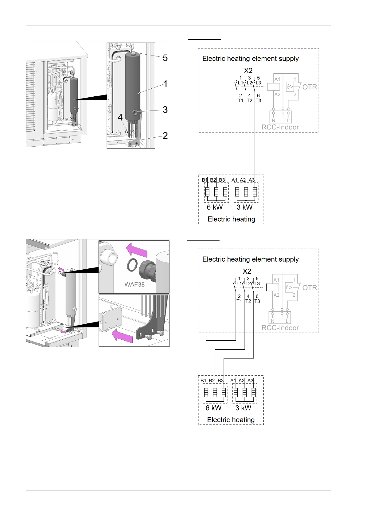
6.2 Heating element and components
Overview: Heating element and components
Abb. 2-18
1 Electric heating element
2 Bracket
3 Temperature sensor T1 for condenser
4 Capillary tube sensor of the OTR
5 Contactor
6 Overtemperature reset (OTR)
Installation manual vampair 19
6 Install electric heating element
Overview: Heating element installed
Abb. 2-19
1 Electric heating element
2 Bracket
3 Primary circuit flow outlet
4 Primary circuit return inlet
5 Vent valve
6.3 Mount heating element
►Mount the bracket and the heating element to the
heat pump as shown.
Abb. 2-20
6.4 Connect the heating element
►Connect the wires of the heating element to the
contactor (X2) according to the desired power:
Power 3 kW: Connect wires A1, A2 and A3 to L1, L2
and L3.
Power 6 kW: Connect wires B1, B2 and B3 to L1, L2
and L3.
20 Installation manual vampair
Other manuals for Vampair
1
Table of contents
Other SOLARFOCUS Heat Pump manuals


Popular Heat Pump manuals by other brands

Enertech
Enertech WD240 Installation & operation manual

Dimplex
Dimplex HPWH 300 Installation and operating instructions

Friedrich
Friedrich VRP7k Service and parts manual

Grant
Grant HPiD6 Installation and servicing instructions

Johnson Controls
Johnson Controls VB09 Installation, operation and maintenance

Viessmann
Viessmann Vitocal 200-S datasheet

Porkka
Porkka VH2164 installation instructions

Enertech
Enertech ZS. Installation & operation manual

Lennox
Lennox 13HPX installation instructions

Bosch
Bosch Geothermal Heat Pumps Applications manual

Hayward
Hayward SUMHEAT HP5131DT3 Installation instructions manual

MICROWELL
MICROWELL HP 1000 GREEN Installation and user manual


