SOLARFOCUS vampair K 08 User manual

Operation manual for the system operator
Read carefully before operating.
DR-0086-EN / v14-201901
Air heat pump vampair

1 About this manual 3
2 Safety information 3
3 Product information 4
3.1 Proper use 4
3.2 Product description 4
3.3 Spare parts 4
3.4 Type plate 4
3.5 CE declaration of conformity 4
3.6 Safety devices 5
3.7 Functional components 5
3.8 Principle of operation 6
3.9 Innovative technologies 7
3.10 Smart Grid Ready 7
3.11 Accessories 8
3.12 Technical specifications 9
3.13 Dimensions 11
3.14 System Overview 11
4 Use and operation 12
4.1 Main screen of the control unit 12
4.2 Operating mode 12
4.3 Selection menu 12
4.4 Customer menu 13
4.4.1 Electricity supplier block 13
4.4.2 Night-time reduction 13
4.4.3 Blocking times for electric heating element/heat
pump 13
4.4.4 User lock 14
4.4.5 Message log 14
4.4.6 Operating hours counter 14
4.4.7 Manual operation 15
4.4.8 Qualified personnel menu 15
5 Heating circuit 18
5.1 Heating circuit settings 18
5.1.1 Heating circuit operating mode 18
5.1.2 General settings 19
5.1.3 Heating curve 19
5.1.4 Cooling mode 21
6 DHW heating 22
6.1 Domestic hot water tank 22
6.1.1 DHW tank settings 23
6.2 Fresh water module - FWM (optional) 23
7 Recirculation control 24
7.1 Circulation settings 25
7.2 Recirculation control - Options 25
8 Buffer tank 26
9 Solar system 27
10 Temperature difference charge control 27
11 mySOLARFOCUS app 28
11.1 Requirements for use 28
11.2 Connecting the control to the internet 28
11.3 Register on the web server 28
11.4 Install app, register user 29
11.5 Add system 29
11.6 Use of the mySOLARFOCUS app 29
11.7 Approve additional users 30
12 Weatherman function 30
12.1 Information 31
12.2 Heating circuit 31
12.3 Domestic hot water 32
12.4 Buffer tank loading 32
13 Maintenance and cleaning 33
13.1 Activities required 33
13.2 Maintenance by qualified personnel 33
13.3 Refrigerant testing obligation 34
14 Troubleshooting 34
14.1 Possible messages: 34
14.2 Reset overtemperature reset 35
15 Shut-down 36
16 Maintenance contract Power Package” 37
17 Manufacturer declaration 38
18 Technical long data sheet - vampair K 10 38
18.1 Average climate 38
18.1.1 low temperature (35°C) 38
18.1.2 medium temperature (55°C) 39
18.2 Colder climate 39
18.2.1 low temperature (35°C) 39
18.2.2 medium temperature (55°C) 39
18.3 Warmer climate 39
18.3.1 low temperature (35°C) 39
18.3.2 medium temperature (55°C) 40
19 Technical long data sheet - vampair K 15 40
19.1 Average climate 40
19.1.1 low temperature (35°C) 40
19.1.2 medium temperature (55°C) 40
19.2 Colder climate 40
19.2.1 low temperature (35°C) 40
19.2.2 medium temperature (55°C) 40
19.3 Warmer climate 41
19.3.1 low temperature (35°C) 41
19.3.2 medium temperature (55°C) 41
20 ErP product data sheet 42
2 Operation manual vampair
Content

1 About this manual
1 About this manual
Software version for control unit
The guide describes the software version 18.080 of
the boiler control ecomanager-touch;Main screen of
the control unit > 12
Language
The language of the original manual is German. All
other language versions of this manual are trans-
lations of the original.
Storage
Keep the manual for the entire service life of the pro-
duct and ready to hand. The manual must be pas-
sed on to the new owner when the product is
dismantled/reused. If the manual is lost or
destroyed, request a new copy from the manu-
facturer.
Tips and Warnings
The tips used in this manual are highlighted with
symbols and signal words. The signal word indi-
cates the level and nature of the danger and how to
avert it.
iIndicates information for correct handling of the
product.
!ACHTUNG - Bei Nichtbeachtung dieser Hin-
weise sind Sachschäden möglich.
DANGER - Failure to comply with this instruc-
tion poses a danger to people.
Limitation of liability
SOLARFOCUS GmbH assumes no liability for injury
or material damage resulting from:
–Failure to observe the instructions in this manual.
–Use of the product for any purpose other than for
its intended use.
–Deployment of unqualified personnel.
–Use of non-approved spare parts.
–Technical modification of the product by the sys-
tem operator.
Warranty, guarantee
See terms and conditions of the SOLARFOCUS
GmbH. and conditions in the chapter Maintenance con-
tract > 37
Manufacturer
SOLARFOCUS GmbH
Werkstrasse 1, A-4451 St.Ulrich
Company register no. 281755x
Tel.: +43 7252 50 002-0, Fax: +43 7252 50 002-10
office@solarfocus.at
www.solarfocus.com
Technical questions about our products
–Service-Hotline
+43 7252 50002-4920
service@solarfocus.at
–For calls from Germany
0180 500 92 10
2 Safety information
Installation and commissioning
–Heat pump may only be serviced and put into
operation by by certified qualified personnel
(SOLARFOCUS service technician or
SOLARFOCUS service partner).
–Install heat pump outdoors only.
–Never disconnect the heat pump from the power
supply (except electrical work). Otherwise risk of
frost damage
Maintenance and repair
–Have repairs done by qualified personnel only
Improper repairs can lead to risks for the user and
impaired operation
–Use original spare parts only
–Have the heat pump serviced annually by qualified
personnel
Handling of refrigerant R410A
–The heat pump uses refrigerant R410A. Work on
the cooling circuit may be performed only by a qua-
lified refrigerant electrician.
–Wear suitable gloves and goggles when working
with refrigerant.
What to do in case of escaping refrigerant
–Escaping refrigerant can cause frostbite if it tou-
ches the exit point. If refrigerant escapes do not
touch any components of the heat pump.
–Avoid skin or eye contact with the refrigerant. In
case of skin or eye contact with the refrigerant, a
doctor should be consulted.
–Switch off heat pump, Contact qualified personnel.
Operation manual vampair 3

3 Product information
3.1 Proper use
The air heat pump vampair may only be installed in clo-
sed hot water heating systems and serves for building
heating and domestic hot water heating.
(fehlender oder ungültiger Codeausschnitt)
3.2 Product description
The air heat pump vampair is a compact air heat pump
for outdoor installation. As standard, it has a cooling
function which extracts heat from the heating surfaces
in the living area (underfloor heating, wall heating) and
cools it by reversing the circulation.
vampair works with inverter technology and Enhanced
Vapourized Injection > 7. The defrosting of the eva-
porator is done by circulation reversal.
Rear side (intake grille)
Fig. 2-1_007AN
Front side (soundproofing slats)
Fig. 2-2_010AN
3.3 Spare parts
For repairs use only original spare parts or parts appro-
ved by the manufacturer (e.g. standard parts).
The manufacturer cannot accept any liability for
damage caused by spare parts not authorised by the
manufacturer.
3.4 Type plate
The type plate is attached to the cover 1(remove
cover 2).
Fig. 2-3_006cAT - position type plate
3.5 CE declaration of conformity
This product complies with European directives and
complementary international requirements. Conformity
is verified with the CE marking, the declaration of
conformity is with the manufacturer.
4 Operation manual vampair

3 Product information
3.6 Safety devices
Overtemperature reset (OTR)
The overtemperature reset (OTR) is a safety device
that prevents overheating of the boiler.
Functioning: The OTR stops the heating element at a
temperature of ~95°C.
The OTR is included in the delivery of the electric hea-
ting element.
Safety valve (to protect against excess pressure in
the system)
The safety valve 1is a safety device for protecting
against overpressure in the water circuit of the heating
system.
Functioning: The valve opens when the system pres-
sure exceeds 3 bar. Water/steam are discharged into
an open drain via a discharge line, which avoids con-
sequential damage to the heating system. The valve is
closed during normal operation.
The safety valve is not included and must be installed
by the customer.
Fig. 2-4_Safety valve integrated into safety group.
3.7 Functional components
vampair K 08 and K10
The fan 2sucks the ambient air (outside air) through
the evaporator 3and blows it out through the sound-
proofing slats 1.
The condensate formed during defrosting of the eva-
porator is discharged through the outlet 8.
Fig. 2-5_005BN
1 Soundproofing slats
2 Fan
3 Evaporators
4 Intake grille
5 Terminal area (electrical connection terminals)
6 Overtemperature reset (OTR) [1]
7 Outdoor temperature sensor
8 Condensate drain
[1] Only when using electric heating element (optional accessory)
Operation manual vampair 5

3 Product information
vampair K 12 and K15
The fan 4sucks the ambient air (outside air) through
the evaporator 6and blows it out through the sound-
proofing slats 3.
The condensate formed during defrosting of the eva-
porator is discharged through the outlet 8.
Fig. 2-6_004cCM - Front side with sound insulation strips
Fig. 2-7_005cCM - Rear side with intake grille
1 Terminal area (electrical connection terminals)
2 Overtemperature reset (OTR) [1]
3 Soundproofing slats
4 Fan
5 Evaporators
6 Intake grille
7 Outdoor temperature sensor
8 Condensate drain
[1] Only when using electric heating element (optional accessory)
3.8 Principle of operation
The function of a heat pump is similar to that of a ref-
rigerator from a technical standpoint, but reversed. The
refrigerator extracts heat from the food to be cooled
and releases it to the room air.
The heat pump vampair withdraws heat from the out-
side air and delivers it to the heating system.
Four processes are decisive in the cooling circuit of
the heat pump:
Evaporation
The evaporator (2) takes the circulating refrigerant
energy from air and changes its state from liquid to
gaseous.
Compression
In an electrically driven scroll compressor 3, the
gaseous refrigerant is heated by compression.
Liquefaction (condensation)
The absorbed thermal energy is delivered to the hea-
ting system. The gaseous refrigerant is cooled in the
condenser (plate heat exchanger) and liquefied again
4.
Expansion
The pressure of the liquid refrigerant is reduced, resul-
ting in partial evaporation. The result is a mixture of
liquid and gaseous refrigerant (= wet steam). The ref-
rigerant cools down.
1 Energy from outside air
2 Evaporators
3 Scroll compressor
4 Condenser
5 Discharge of heating heat
6 Expansion valve
7 Economizer-heat exchanger (for Enhanced
Vapourized Injection)
8 Enhanced Vapourized Injection
6 Operation manual vampair

3 Product information
3.9 Innovative technologies
Inverter technology
The scroll compressor not only works in on/off mode,
but is operated with power control (modulating, accor-
ding to the current power requirement).
Advantage:
–Precise power adjustment.
–Increased efficiency through reduced clocking.
–Quieter operation on average due to reduced speed
in the partial load range.
–Reduction of the power of secondary drives (fan,
primary circuit pump)
Intermediate steam injection
In the scroll compressor, wet steam is injected from
the economizer heat exchanger for cooling.
Enhanced Vapourized Injection injection increases
efficiency, while the power requirement is reduced at
the same time. Thus higher flow temperatures and
higher heating output (especially at low outside tempe-
ratures) are possible. The compression temperature
decreases, increasing the life expectancy of the
compressor.
3.10 Smart Grid Ready
The SG-Ready label is a label for heat pumps, the con-
troller of which meet the conditions for inclusion in a
future, intelligent power grid (smart grid = SG).
Purpose of this function: Load balancing in the elec-
tricity networks of the energy supply companies
(ESCs).
The technique: The energy supply company sends
signals to the heat pump control (by means of a so-cal-
led ripple control receiver) and can thus influence the
operating mode of the heat pump within a defined
range.
This means:
–At peak loads, the heat pump can be switched off.
–Surplus electricity can be converted into thermal
energy and stored in the DHW tank or the heating
circuit (e.g. screed of the underfloor heating sys-
tem).
Electricity supplier block
The ESC may switch off the heat pump for a maxi-
mum of 2 hours (depending on the rate up to 3 times a
day) and grants the consumer a reduced rate.
Smart Grid
The ESC cannot switch off the heat pump temporarily
only when needed, but there are four defined operating
modes in the heat pump control, which the ESC may
trigger depending on the power grid load condition.
Operating state 1 - shut down
–The heat pump is switched off by the ESC (for a
maximum of 2 hours, equivalent to the current
ESC block).
Operating state 2 - normal operation
–The control operates in accordance with the
setpoint temperatures set by the system operator
with regard to room heating and DHW storage.
Operating state 3 - start-up recommendation
–The DHW tank is charged to its required tem-
perature (if the required temperature has not yet
been reached).
–The heating circuit is activated [1]. The required
flow temperature is increased by an adjustable
value (can be defined for each heating circuit).
[1] if possible due to the settings, e.g. outside shutdown tem-
perature is not reached, ....
Operating state 4 - Startup command
–In this operating state it is possible to set whether
only the compressor or the compressor and the
electric heating element are activated.
–The DHW tank is charged (within the release
times) by an adjustable value above the setpoint
temperature.
–The set room temperature is increased by an
adjustable value (can be defined for each heating
circuit).
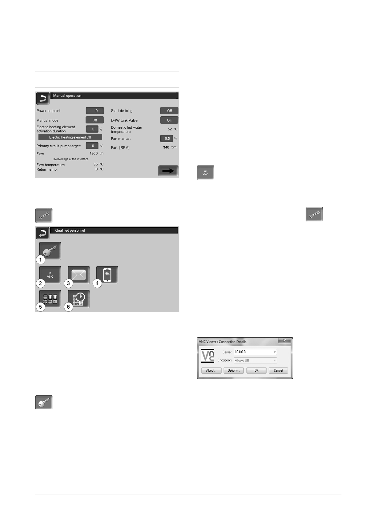
The screens with the corresponding setting
parameters are located in the Service Menu |Smart
Grid button. To enter the service menu of the control, a
qualified personnel code must be entered.
Operation manual vampair 7

3 Product information
3.11 Accessories
Electric heating element
–Optional accessories, Art. 25200
–Depending on the type of connection, the electric
heating element achieves an output of 3, 6 or 9
kW; installation at the heating circuit flow.
–Scope of delivery includes overtemperature reset
button (OTR), contactor and connection material
–Further information Please refer to the installation
manual of the heat pump.
Fig. 2-8_004BE - Electric heating element mounted
Carrying aid
–Optional accessories, Art. 25300
–To carry, lift and move the heat pump
–4-piece
Fig. 2-9_001BG
8 Operation manual vampair

3 Product information
Operation manual vampair 9
3.12 Technical specifications
vampair K 08 K 10 K 12 K 15
Recommended building heat load [1] [kW] 5.7 7.8 9.4 15
SCOP, moderate climate W35/W55 (EN 14825) 4.2/3.4 4.73/3.8 4.4/3.4 4.95/3.85
ηs seasonal room heating energy efficiency, moderate cli-
mate 35 / 55 °C [%] 165/133 186/149 173/133 195/151
Energy data
Energy efficiency class, moderate climate W35/W55 A++ /
A++ A++ / A++ A++ /
A++ A++ / A++
Energy efficiency class incl. boiler control, moderate climate
W35/W55
A++ /
A++
A+++ /
A+++
A++ /
A++
A+++ /
A+++
Heat output according to EN 14511
Max. heat output at A7/W35 [kW] 8 9.5 14 18
Max. heat output at A2/W35 [kW] 7.2 9.5 12.5 18
Max. heat output at A-7/W35 [kW] 5.7 7.5 10.0 14.7
Max. heat output at A-10/W35 [kW] 5.3 7.0 9.4 13.7
Heat output at A10/W35 [kW] 4.57 6.09 6.46 11.56
Heat output at A7/W35 [kW] 4.29 6.19 6.06 11.98
Heat output at A2/W35 [kW] 3.94 5.47 7.31 9.46
Heat output at A-7/W35 [kW] 5.68 5.83 10.08 11.26
Heat output at A7/W55 [kW] 4.41 6.36 6.0 11.72
Cooling performance figures according to EN 14511
Max. cooling capacity A35 / W18 [kW] 5 6 10 15
Max. cooling capacity A35 / W7 [2] [kW] 4 5 8 13
Power consumption
Fan power consumption max. [W] 35 81 60 170
Power consumption at A10/W35 (EN 14511) [kW] 0.86 1.13 1.2 2.1
Power consumption at A7/W35 (EN 14511) [kW] 0.88 1.24 1.2 2.4
Power consumption at A2/W35 (EN 14511) [kW] 0.95 1.25 1.7 2.1
Power consumption at A-7/W35 (EN 14511) [kW] 1.8 1.66 3.15 3.24
Power consumption at A7/W55 (EN 14511) [kW] 1.4 1.92 1.8 3.43
Output figures according to EN 14511
COP output coefficient at A10/W35 5.3 5.4 5.4 5.5
COP output coefficient at A7/W35 4.83 4.97 5.0 5.0
COP output coefficient at A2/W35 4.15 4.37 4.2 4.49
COP output coefficient at A-7/W35 3.16 3.51 3.2 3.47
COP output coefficient at A7/W55 3.17 3.32 3.3 3.41
Sound data
Sound power level (EN 12102) [dB(A)] 45 50 48 55
Sound pressure level at 5 m distance, in free field Silent
Mode [dB(A)] 18 21,7 22 22
Sound pressure level at 3 m distance, set up in the open
Silent Mode [dB(A)] 25.5 29,2 29.5 29.5
Sound pressure level at 5 m distance, set up in the open
Silent Mode [dB(A)] 21 24,7 25 25
Sound pressure level at 4 m distance, set up against a wall
Silent Mode [dB(A)] 26 29.7 30 30
Sound power level max. (day/silent) [dB(A)/
dB(A)] 46 / 43 54 / 47 50 / 47 63 / 47

vampair K 08 K 10 K 12 K 15
Cooling circuit
Refrigerant R410A
Refrigerant fill level [kg] 4.78 6.7
GWP (according to EN 378), kg CO2 equivalent per kg [kg/kg] 2088
CO2 equivalent [t] 9.98 13.99
Condenser material 1.4401/Cu
Operating limits
Operating limit outside air min. [°C] -22
Operating limit outside air max. [°C] 35°C
Operating limit heat-side air min. [°C] 26°C
Operating limit heat-side air max. [°C] 65°C
Operating limit outside air at W60 [°C] -22°C
Operating limit outside air at W65 [°C] -5
Water hardness [°dH] 4 – 8.5
pH value 7.5 – 9
Conductivity [μS/cm] 10 – 500
Free chlorine [mg/l] < 0.5
Electrical data
Protection type (IP) IP X4
- Single-phase design (K 08.1, K10.1, K 12.1, K 15.1)
Number of compressors 1
Compressor connection ~230V, 50 Hz,
5,5kW
~230V, 50 Hz,
8kW
Boiler control connection ~230 V 50Hz
Compressor fuse [A] 25 35
Boiler control fuse [A] 10 10
Starting current [A] 15 25
- Three-phase version (K 08.3, K10.3, K 12.3, K 15.3)
Number of compressors 1
Compressor connection ~400V, 50 Hz;
5,5kW
~400V, 50 Hz;
8kW
Boiler control connection ~230 V, 50Hz
Auxiliary heating power consumption max. [kW] 3 / 6 / 9
Auxiliary heating connection ~400V, 50Hz
Compressor fuse [A] 13 16
Boiler control fuse [A] 10 10
Auxiliary heating fuse [A] 13 13
Starting current [A] 6.5 8
Dimensions
Weight [kg] 325 390
Connections
Connection for heating flow/return ["] G 5/4" OT
Flow rates
Air flow rate [m³/h] 1300 2900 2000 4400
Heating flow rate min. [l/h] 520 520 800 800
Defrosting flow rate min. [l/h] 1300 1300 1500 1500
Heating flow rate (EN 14511) at A7/W35 and 5 K [l/h] 1080 1080 2080 2080
[1] At standard ambient temperature -14°C, heating limit temperature 15°C, VL35°C/RL28 °C, taking into account 5% share of peak load heat
generator (excluding hot water)
[2] With expansion set low-temperature cooling
3 Product information
10 Operation manual vampair

3 Product information
Operation manual vampair 11
3.13 Dimensions
3.14 System Overview
vampair with heating circuit and DHW tank

4 Use and operation
4 Use and operation
Touch display for operation
When the display is supplied with power, the ecomana-
ger-touch boiler control starts. The control is started up
to show the main screen.
iOperate the touch display with your fingers, do
not use any hard objects.
If no inputs are made for 5 minutes (factory setting),
the display will switch to standby mode.
Tapping the display again restarts the display with the
main screen.
Buffer battery in operating element
A replaceable buffer batter (CR2032) ensures that data
(time, settings) are retained in the operating element
when the supply voltage is switched off.
4.1 Main screen of the control unit
Fig. 2-10_01-001va
1 Software version for control unit
2 outside temperature
3 Power (speed of the compressor)
4 Operating mode
5 Flow temperature of the heat pump
6 Status line
Tapping the main screen changes to the Selection
menu > 12
4.2 Operating mode
STOP
Heat pump and electric heating element are switched
off. No heating requirements of the consumers are ful-
filled.
iFrost protection function is guaranteed. If the
outdoor temperature falls below +2°C (factory
setting), the primary circuit circulation pump
and, if necessary, the compressor (or electric
heating element) are switched on.
START
After pressing the START button, the heat pump is
ready for operation, and is able to fulfil heating
requests from the consumers. The heat pump goes
into standby status as soon as a heating request is ful-
filled, or the time release >4.4.3 Blocking times for
electric heating element/heat pump > 13 is no longer
present.
electric heating element only
The heat pump is switched off. Heating requests are
met by the electric heating element. Usage: For excep-
tional situations, e.g. in case of a compressor ope-
rating fault.
Automatic defrost
At temperatures below 5°C, the water contained in the
outside air settles on the evaporator of the heat pump
in the form of frost and ice.
The defrost is automatically triggered by the control at
regular intervals by heat is supplied to the evaporator
by circulatory reversal.
4.3 Selection menu
Fig. 2-11_01-132va-01
1 Customer menu > 13
2 Heating circuit > 18
3 DHW heating > 22
4 Weatherman function (optional) > 30
5 Information
12 Operation manual vampair

4 Use and operation
4.4 Customer menu
Fig. 2-12_01-025va
1 Electricity supplier block > 13
2 Night-time reduction > 13
3 Blocking times for electric heating ele-
ment/heat pump > 13
4 User lock > 14
5 Message log [1] Record alarm and notifications
> 14
6 Operating hour counter > 14
7 Manual operation > 15
8 Qualified personnel menu > 15
[1] Button is only visible if a message is active.
4.4.1 Electricity supplier block
Some electricity supply companies (ESCs) are gran-
ting discounted electricity rates for heat pumps. For
this they reserve the right to interrupt the delivery of
electricity at certain times.
Two ways for the controller to recognise these sche-
duled power cuts as being proper (and thus not inter-
preted as an operating fault):
–By the electrical ESC-lock signal (in case of doubt
ask your electrician)
–By recording on the ESC Block screen
If the ESC's electrical lock signal is not available,
enter the blocking times announced by the ESC in this
screen:
Fig. 2-13_17-004-01
!CAUTION Before activating the blocking
times, the screed drying must be completed.
Failure to do so may damage the screed.
4.4.2 Night-time reduction
This function is used for possible noise reduction
during the night-time hours. This is done by limiting the
fan 1and/or compressor speed 2.
Fig. 2-14_17-005
iPlease note that the power restriction of the
heat pump may increase the consumption
during auxiliary heating (e.g. electric heating
element).
!CAUTION - Attention: Before activating the
reduction, the screed drying must be com-
pleted.
4.4.3 Blocking times for electric heating ele-
ment/heat pump
Function: The electric heating element and/or the heat
pump can be locked in desired time ranges (e.g. to
give priority to other energy source such as solar sys-
tem, log wood boiler, ...).
Fig. 2-15_17-006
Blocking time in effect for:
–Electric heating element
–Heat pump
–Electric heating element and heat pump
Operation manual vampair 13

4 Use and operation
4.4.4 User lock
Fig. 2-16_01-001va-01
The function serves as protection against unaut-
horised modification of the control parameters. When
the user lock is active, the parameters of the individual
screens are displayed but cannot be changed. The
active user lock is indicated by the padlock icon 1in
the screens.
User lock screen
Fig. 2-17_02-003
Enter the password 2
To define a new password (maximum 20 characters).
Password 3
The currently valid password is displayed.
User lock 4
Off: The user lock is switched off.
On: Switches on the user lock function. If the display
is not touched for one minute, the user lock is active in
the screens.
Password reset 5
The current password is reset to the value solarfocus.
Accept as new password 6
Enter a new password in the input field and press the
button. Note on screen keyboard; Confirm input with
the button.
4.4.5 Message log
Fig. 2-18_12-006
Every fault message which has occurred in the control
unit is recorded here, with the time that it began and
ended. The message with the highest priority is high-
lighted in red, acknowledged messages are highlighted
in green.
Press the 3button to quit messages. Button 1opens
the power failure log, button 2deletes individual mes-
sages in the message log.
Possible messages > 34
4.4.6 Operating hours counter
Fig. 2-19_01-043va
Fig. 2-20_17-012
14 Operation manual vampair

4 Use and operation
4.4.7 Manual operation
Function: Test (correct wiring, function) of the indi-
vidual components possible, such as electric heating
element, primary circuit pump, fan.
iUse this screen only for commissioning and
service work by qualified personnel.
Fig. 2-21_17-009
4.4.8 Qualified personnel menu
Fig. 2-22_01-126-07
1 Service menu > 15
2 IP VNC (for remote access) > 15
3 Sending emails > 16
4 mySOLARFOCUS-App > 28
5 Language selection > 17
6 Date and time > 17
4.4.8.1 Service menu
In the Service menu there are technical (factory pre-
defined) settings. These can only be accessed by qua-
lified personnel (code input required).
4.4.8.2 IP VNC (for remote access)
The control unit ecomanager-touch allows access to the
control unit screens from a PC or mobile device (e.g.
smartphone). This is effected via VNC (Virtual Net-
work Computing) software. The control has an
integrated VNC server, while the VNC Viewer, which
is available free of charge on the Internet, is required
for remote access.
A cable connection is required on site for the connec-
tion of the control unit to the router. Use the Ethernet
socket (type RJ45) on the rear of the control panel
(Touch display).
iInstallation and configuration of this function
must be performed by the customer (i.e. not
included in the commissioning, service and sup-
port activities).
The following points are helpful for setting up a PC/-
router to control the VNC server, which requires know-
ledge of networking technology.
IP configuration
►To access the IP-VNC icon, select it in the control
–Selection menu screen
–Customer menu screen
–Trained qualified personnel button
►Enter the data for your router. Recommend pro-
cess:
–Select DHCPON.
ÄThe IP address is determined.
–Select the DHCP OFF + Apply button .
–The IP address must be unique in each Ethernet
network and is dependent on the other network
components (PC, modem/router, etc.).
–Recommendation: Set a fixed IP address (=DHCP
OFF), i.e. the control unit has a constant IP
address.
Version 1: Installation of VNC viewer for access
from a local PC (PC in the home network)
►Download the free VNC Viewer from the Internet,
install it on the PC and start the application.
►Enter the previously defined IP address of the con-
trol.
–As soon as the VNC Viewer is able to access
the control unit, a password must be entered.
–The password predefined by the manufacturer
is solarfocus
–After login, the screen view of the control unit is
available.
Operation manual vampair 15

4 Use and operation
Changing the VNC password
Fig. 2-23_01-054-02
►Press the Change VNC password button on the
IP setup view.
►To change it, first enter the old password, then the
new password, then press the Accept button.
►The new password must be used to log on after
restarting the VNC Viewer on the local PC.
►Press the Reset password button to reset the
password to the default password solarfocus.
Version 2: Installation of VNC viewer for access
from an external PC (PC outside the home net-
work)
–The user's local router does not always have the
same IP address on the Internet (it is allocated by
an Internet Service Provider – ISP).
–Nevertheless, Dynamic Domain Name Systems,
also referred to as DynDNS or DDNS, allows
access to the router.
–These systems allow a unique host name to be
assigned on the Internet; the unique name is then
also entered in the router. If the router is then assi-
gned a different address by the ISP, it enters the
updated IP address as the defined host name on
the DynDNS server. The router and therefore the
home network can then be reached using this host
name.
–To create a connection with the control unit, a port
diversion is required from the external port of the
router[1] to the IP address and to VNC port 5900 of
the control unit.
[1] Port 5950 is recommended
iAvoid any port forwarding from external port
5900 of the router to IP address and VNC port
5900 of the control.
4.4.8.3 Sending e-mails
Function: The boiler control ecomanager-touch auto-
matically sends status e-mails and alarm e-mails to
predefined addresses if required.
Status e-Mail: An automatic email (e.g. sent daily) pro-
vides information on the current heat pump status.
Alarm email: a message is sent when a fault occurs.
iInstallation and configuration of this function
must be performed by the customer (i.e. not
included in the commissioning, service and sup-
port activities).
Fig. 2-24_01-048
Outgoing mail server 1
Enter the access data for the e-mail server you use.
Fig. 2-25_01-049
Use SSL: Select if the e-mail server uses a TLS/SSL
encryption protocol.
Address book 2
A maximum of 10 contacts can be added. If there are
several addresses for a contact, these should be
comma-separated.
Write e-mail 3
Used to manually send e-mails. The recipient’s
address can be selected from the address book using
To and CC or manually entered in the recipient line.
16 Operation manual vampair

4 Use and operation
Alarm test 4
Used to test the e-mail settings. Pressing the button
sends an e-mail to the Recipient status email.
Send alarm email 5
Activates/deactivates the automatic sending of alarm
e-mails. The sending of status e-mails is not affected
by this.
Alarm configuration 6
Settings for the alarm e-mails to be sent automatically.
Fig. 2-26_01-051
Alarm subject: is used for all alarm e-mails and status
e-mails, therefore it should be as meaningful as pos-
sible (e.g. system type / name of system operator; 40
characters available).
Alarm groups: For prioritisation of the alarm messages
(e.g. Alarm group 1 receives all messages, Alarm
group 2 receives only non-critical messages, such as
information on necessary maintenance, etc.).
Status e-Mail: Set time at which the status e-mail is
sent. The automatically generated content of the sta-
tus e-mail is:
–Current status of the heating system
–Fault present, and which
Alarm selection: This is where you define which alarm
group is reported for which event.
4.4.8.4 mySOLARFOCUS app
Pressing the button displays the screen with infor-
mation relating to online registration for the
mySOLARFOCUS app (serial number, PIN,status,
etc.) > Fig. 2-46, page 28
Detailed information on using the mySOLARFOCUS
app > 28
4.4.8.5 Language selection
Fig. 2-27_02-006
4.4.8.6 Date and time
Fig. 2-28_02_005
switchover from summer/winter time is made auto-
matically when the Switchover Summer-Winter para-
meter has the value Europe. Switchover takes place
on the last Sunday of the months of March and Octo-
ber. If America is set, the clock is changed to summer
time on the first Sunday in April.
Operation manual vampair 17

5 Heating circuit
5 Heating circuit
Fig. 2-29_08-003va
1 outside temperature
2 Average outside temperature
3 Room temperature (optional)
4 Temperature of the energy source (e.g.buffer)
5 Flow temperature of the heating circuit
6 Position of the heating circuit mixer
0 % - the mixer is closed, the heating circuit is supplied from
the heating circuit return.100% - the mixer is open, the hea-
ting circuit is supplied from the flow.
7 Info line: Heating requirement (Yes/No) to the
energy source.
8 Status line of the heating circuit
9 Heating circuit settings > 18
10 Display of the heating circuit operating mode
set on the optional room temperature controller
(Art. no. 6160)
5.1 Heating circuit settings
Fig. 2-30_08-504va-01
1 Heating circuit operating mode > 18
2 Room settings
(Button is only visible when the Room effect parameter is
set to On or Sliding;this can be found in the Specialist per-
sonnel system parameters)
3 General settings > 19
4 Heating curve > 19
5 Cooling mode > 21
5.1.1 Heating circuit operating mode
Heating mode
The heating circuit pump is activated. A shutdown
occurs whenever
–the external shutdown temperature for heating
mode is reached
–when a room temperature sensor is used and
where room nominal temperature for heating mode
has been reached.
The heating circuit is supplied with the calculated inlet
nominal temperature > Fig. 2-31.
Reduced mode
Heating circuit pump is activated. A shutdown occurs
whenever
–the external shutdown temperature for reduced
mode is reached.
–a room temperature sensor is used and where
room target temperature for reduced mode has
been reached.
The heating circuit is provided with the reduced tem-
perature, i.e. calculated inlet nominal temperature
minus reduction;> Fig. 2-31.
18 Operation manual vampair

5 Heating circuit
Time switching
In this operating mode, the timed switch-over between
Heating mode and Reduced mode is defined. You can
enter the times for heating mode Daily or In blocks.
Usage example: Heating mode should be active during
the day, but be changed to reduced mode at night.
Switch off heating circuit
The heating circuit pump and heating circuit mixing
valve are switched off. The anti-freeze function for the
heating circuit is enabled (i.e. the heating circuit pump
is switched on whenever the ambient temperature
drops below the anti-freeze temperature).
Holiday mode
Holiday mode deactivates the active operating mode
for the entered duration.
activates the frost protection mode for the hea-
ting circuit for the duration of the holiday.
activates the reduced mode for the heating cir-
cuit for the duration of the holiday.
This icon indicates an activated holiday mode in
the heating circuit screen.
5.1.2 General settings
Cutoff temperature
If the outdoor temperature exceeds the value set here,
the heating circuit pump is switched off and the hea-
ting circuit mixer closes.
Cutoff temperature for heating mode: 18°C
Cutoff temperature for reduced mode: 5°C
iThis means: the heating circuit is normally auto-
matically switched off during the summer
month due to the outdoor temperature.
You can also switch the heating circuit off
manually (=operating mode: Switch off heating
circuit).
Anti-freeze temperature
If the outdoor temperature drops below the value set
here, the heating circuit pump is switched on.
Buffer difference
The heat pump starts when the tank temperature top
falls below the required flow temperature minus the buf-
fer difference.
Example:
- Current flow required temperature = 50°C
- Buffer difference = 5°C
The heat pump starts as soon as tank temperature top
< 45°C.
A negative buffer difference value is added, i.e. the
heat pump is switched on sooner.
Example:
- Current flow required temperature = 50°C
- Buffer difference = - 5°C
The heat pump starts as soon as tank temperature top
< 55°C.
Outdoor temperature delay
The delay set here is used to determined an average
value for the outdoor temperature (= Average outdoor
temperature).
The heating circuit pump switches on if the Average
temperature and the Current outdoor temperature fall
below the cutoff temperature (within the heating
period), or below the reduced mode cutoff temperature
(outside the heating period).
The heating circuit pump switches off again as soon
as the current outdoor temperature rises above the
value of the cutoff temperature.
Heating circuit name
Individual naming of the heating circuit is possible.
5.1.3 Heating curve
The heating circuit flow temperature is controlled by
the heating circuit operating mode > 5.1.1 and by the
outdoor temperature. The heating curve represents the
relationship between these two temperatures. I.e. the
control unit uses the outdoor temperature to calculate
the temperature (=calculated nominal flow tem-
perature) with which the heating circuit is supplied.
In heating mode the heating curve for heating mode 4
(red) is used.
In reduced mode the heating curve for reduced mode 5
(= heating curve for heating mode minus reduction) is
used.
The heating curve must be adapted to suit each buil-
ding and its heating system.
Operation manual vampair 19

5 Heating circuit
2-point heating curve
Fig. 2-31_08_008_01
1 Maximum heating circuit flow temperature[1]
2 Calculated required flow temperature
3 Reduction (the value by which the reduced tem-
perature is lower than the heating temperature)
4 Heating curve for heating mode (shown in red)
5 Heating curve for reduction mode (blue)
6 Minimum heating circuit flow temperature[1]
7 Flow temperature at outside temperature -15°C
8 Flow temperature at outside temperature +15°C
!1) CAUTION - This temperature is system-spe-
cific and must be agreed with the heating engi-
neer. Only to be set by qualified personnel.
The desired heating circuit nominal flow temperature in
heating mode is set for an outside temperature of -
15°C 7and +15°C 8. Between these outside tem-
peratures, the nominal flow temperature is calculated
from the characteristics of the heating curve (inter-
polated).
Example for calculation of nominal flow tem-
perature (see the following illustration):
Flow temperature at outside temperature of -15°C =
45°C
Flow temperature at outside temperature of +15°C =
22°C
Current external temperature =-5°C
In the heating circuit operating mode Heating mode,
this applies:
> The computed flow nominal temperature (Pos.9) is
37.4°C
> The heating circuit is supplied with 37.4°C.
In the heating circuit operating mode Reduced mode,
this applies:
Reduction =10°C
> The computed flow nominal temperature (Pos.10) is
27.0°C
> The heating circuit is supplied with 27.0°C.
Fig. 2-32_08_008_03
Adaptation of the 2-point heating curve (in hea-
ting mode)
iNote the currently set temperature before you
change the values.
A change in heating curve cannot be felt immediately.
Instead, this depends largely on the kind of heat dis-
tribution system (e.g. underfloor heating) and the buil-
ding standard (brick, lightweight construction etc.). It
is advisable to adapt the heating curve in small incre-
ments (+/- 2°C) with corresponding pauses (1 to 2
days). Depending on the current outside temperature,
different adjustments need to be made.
Current
outside tem-
perature
Perceived room
temperature
Recommended adap-
tation of heating curve
-15°C to -
5°C
too cold Increase temperature
value at 7
too hot Reduce temperature
value at 7
20 Operation manual vampair
Other manuals for vampair K 08
1
This manual suits for next models
3
Table of contents
Other SOLARFOCUS Heat Pump manuals
Popular Heat Pump manuals by other brands

Carrier
Carrier 38QB Installation, Start-Up and Service Instructions

Lennox
Lennox Elite XP13-018-230 installation instructions

Haier
Haier GE UUC112WC Series installation instructions

Lennox
Lennox FCM 85 Installation, operating and maintenance

Trane
Trane 4TWB4018G Installer's guide

Robur
Robur GAHP-GS Installation, user and maintenance manual