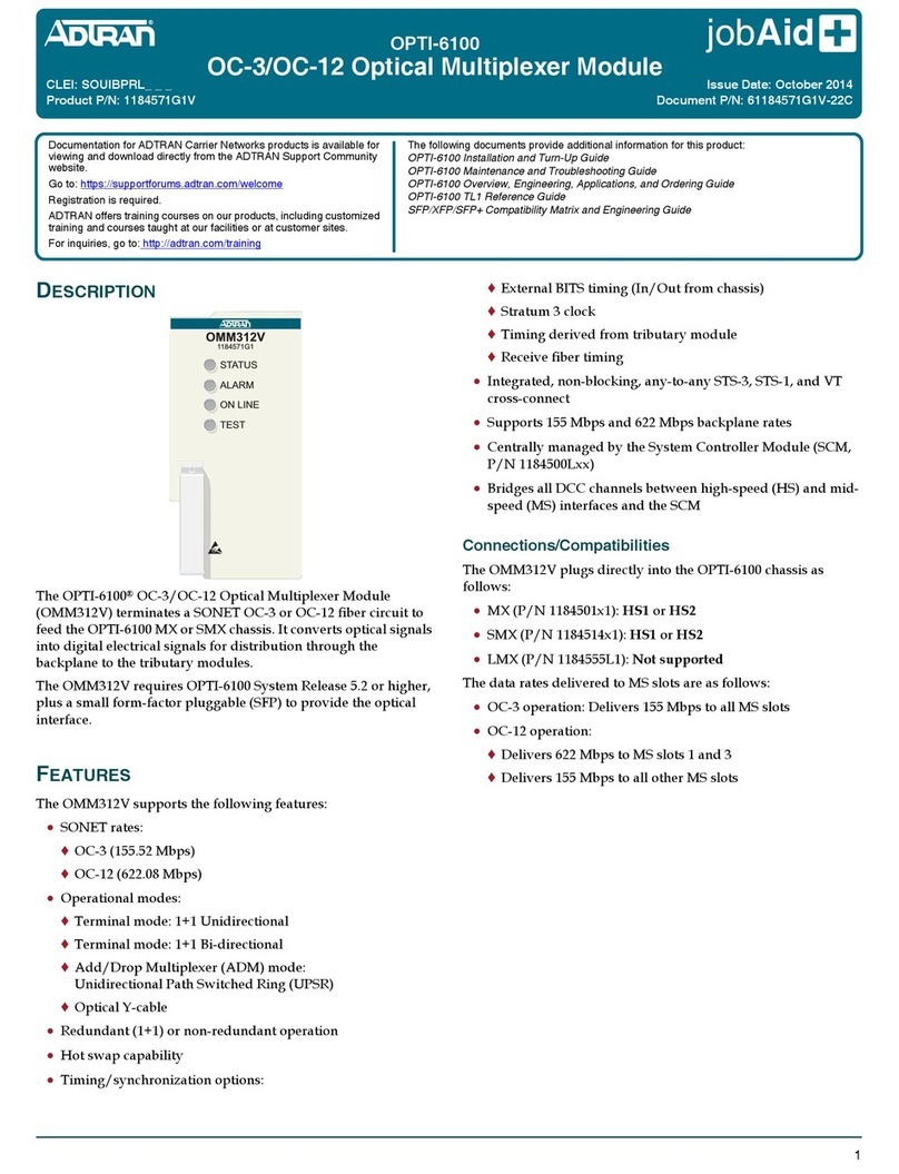
Power Unlocked by Design
Quick Start – Solaria PowerXT-R-AC Module
© 2018 Solaria Corporation All rights reserved. Contents Subject to change. September 12, 2018
Before installing the AC module, the microinverters must be lifted from the shipping position. Turn the AC module
so that the microinverter faces you. Using both hands, lift the microinverter up. You will hear four clicks as the
microinverter locks into the installation position. Ensure the four latches are locked, and that the microinverter is
not tilted.
- If applicable, turn ON the AC disconnect or circuit breaker for the branch circuit.
- Turn ON the main utility-grid AC circuit breaker. Your system will start producing power
after a fi ve-minute wait time.
- Check the LED on the connector side of the microinverter
3. Prepare the AC module
4. Connect the module to the Q cable
5. Mount the module per racking manufacturer instructions and ensure proper grounding
6. Energize!
LED COLOR INDICATES
Flashing green Normal operation. AC grid function is normal there is communication
with the Envoy.
Flashing orange The AC grid is normal but there is no communication with the Envoy.
Flashing red The AC grid is either not present or not within speci cation.
Solid red There is an active “DC Resistance Low, Power Off” condition or “GFDI” fault.
To reset, refer to “DC Resistance Low – Power Off Condition” below.
The Microinverter LED
