Solaric MIG-HMP50 User manual
1
MIG-HMP50
INSTRUCTION MANUAL

2
The SOLARIC MIG-HMP50 solar power system consists of a 50W solar panel,
a solar charge controller, battery, mod sine inverter and comes with 2 LED light
bulbs, a multi-headed USB charger, and a DC fan. Solar power is converted into
electricity; under the regulation of solar controller, the converted electricity is
stored into the battery (this process is called charging). When using the device,
turn it on, and the battery will supply power for the load (this process is called
discharging). The main function of controller is to regulate the process of
charging and discharging. When the battery is too drained, the controller will cut
off the power automatically to protect the battery from over discharging; when
the battery is full, but the solar panel is still supplying power, it will start over
charging protection automatically.
After opening the packaging, please read the manual and operate accordingly. It
will prolong the service life of this system.
Attention
Please read the following messages before operating
1. The system is designed to supply power for family / home use.
2. Please put the case indoor in a dry place. It is not waterproof
3. Please put the case in a place where children cannot reach
4. Do not connect the system with other generators, such as wind driven generator
and diesel driven generator
5. Please cover the solar panels so it is not "live" before you connect the system
6. Be careful because a spark may occur when connecting
7. Put wires in a protective pipe if you want to lay them on the ground
8. Please check the batteries regularly; refresh startup environment; check its
polarity and connection to make sure the wires are not eroded or placed incorrectly.
9. Make sure the system is turned off before connecting wires.
10. Do not connect the solar panel with the incorrect polarity; put the wires in places
where it is not easy to reach after connection.

3
11. Do not exceed the load limit that the system can supply, or it may cause damage
to the system.
1:Set (DC switch)
2:Radio & MP3 player
3:DC5V output port
4:Battery quantity
5:AC Indicator light
6:DC12V output port
Remove the packaging:
Please open the packaging and check whether the system is damaged
during transportation; make sure there are all the accessories. Please
contact the manufacturer or distributor immediately, if you find it is
damaged or some accessories are missing.
4
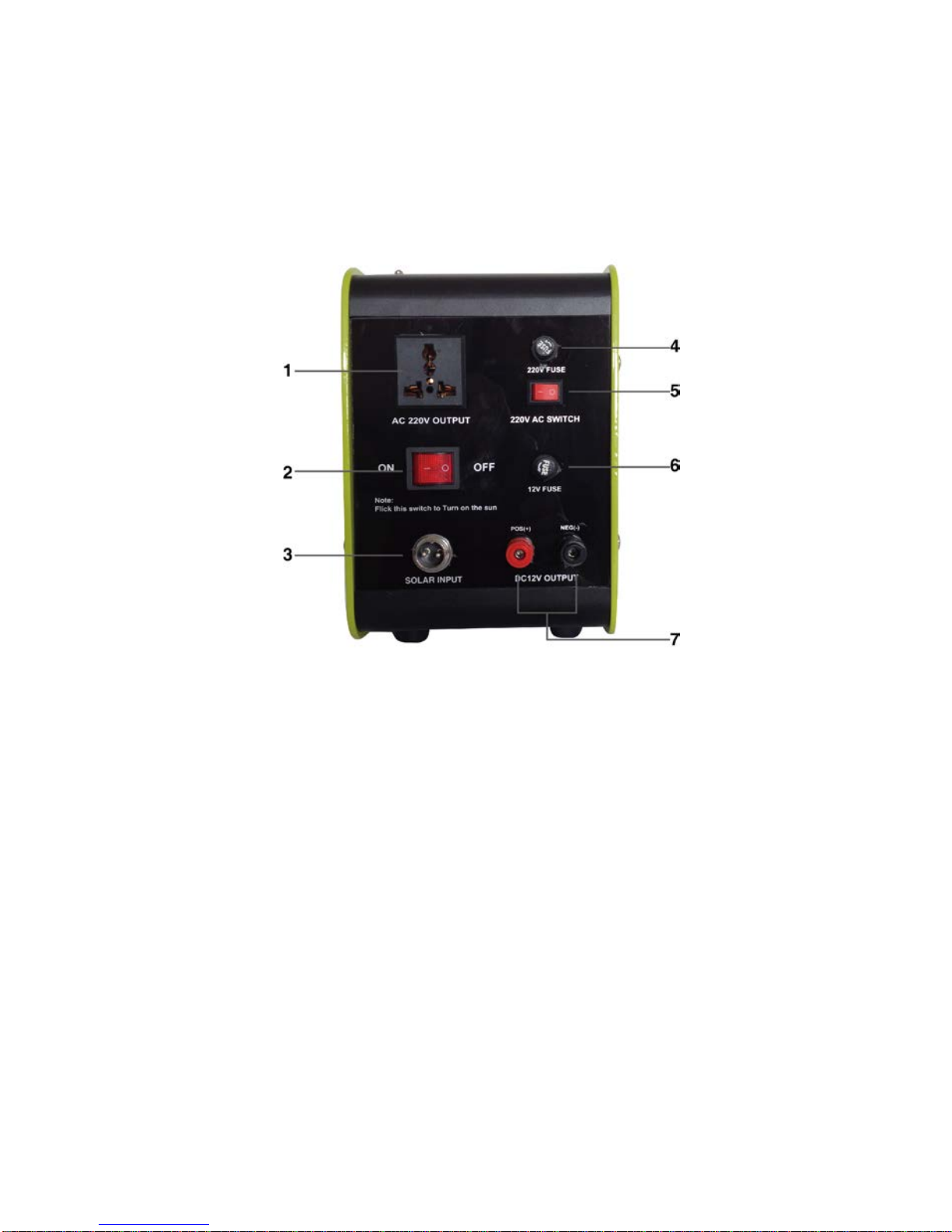
Back panel show as below
1: AC Output ports
2:Battery main switch(Attention:switch must be in the ON position when charging)
3:Solar panel charge input port
4:AC fuse
5:AC switch
6:DC12V fuse
7:DC12V Output port
5
Installation
Steps:
1. The solar panels should be installed in assigned places; Attention: when installing, the solar
panel should face toward the sun, and the best angle of inclination is 15° (according to the
local latitude) to assure the solar panel will work normally. Do not install the panel in shade
or even partly shaded areas
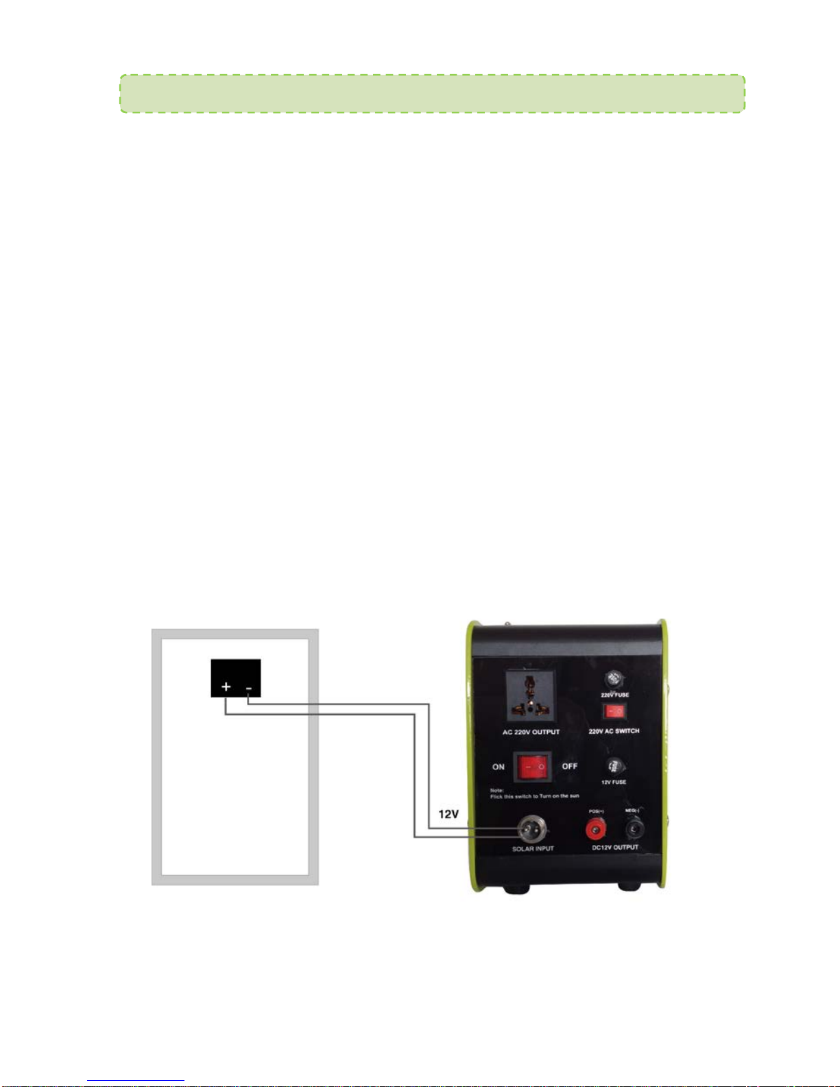
2. Please connect the polarity of solar panel correctly( the red wire stands for positive pole,
and blue or black wire, negative pole)
3. Please plug in the solar charging socket of the case with the output plug of solar panel;
make sure all the wires are connected correctly. Turn on the earth leakage circuit-breaker (the
main switch), and then you can operate the system normally.
Solar panel is connected as the picture shows
Attention:
Please connect the wires correctly as the picture shows. Solar panels are
installed outdoors; all other equipment should be installed indoors.
Warning: electric shock hazard! Photovoltaic array may produce high
voltage; please cover the solar panel before connecting
6
Solar power system control panel function introduction
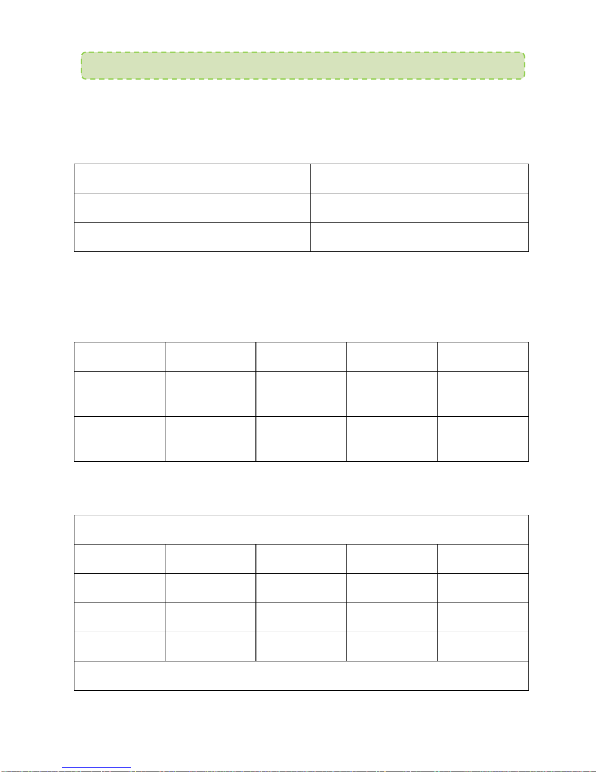
When system is harvesting sun,the charge indicator light is green. That
means the system normal. When the battery is overvolted, the green indicator
flashes quickly.
Indicator state
System state
Steady on
Normal charge
Quick flashing
Battery overvoltage
Battery status indicator:When battery indicator light is red & slow
flashing,battery is low voltage. When battery indicator light is red & quick
flashing, and output is off. The battery is discharge.
LED1
LED2
LED3
LED4
System state
Slow flashing
×
×
×
Battery low
voltage
Quick
flashing
×
×
×
Battery
discharging
“○” Light is on “×” Light is off
Battery voltage rise process
LED1
LED2
LED3
LED4
System state
○
○
×
×
>
12.8V
○
○
○
×
>
13.4V
○
○
○
○
>14.1V
Battery voltage reduction process

7
○
○
○
×
<
13.4V
○
○
×
×
<
12.8V
○
×
×
×
<12.4V
“○” Light is on “×” Light is off
Loading state indicator:
When system is charging, the indicator light is on. When the loading voltage
over 1.25 times rated load current for 60 seconds,or 1.5 times rated load
current 5 seconds, it means it is overloaded, and the indicator light will flash
slowly. If there is a short circuit, it will flash quickly.
Loading status indicator
Indicate status
System state
Normally on
Load open
Off
Loading off
Low flashing
Over load
Quick flashing
Short out
Second: System set operation
· Setting the battery type: Press and hold the set switch for 5 seconds,
Choose the battery type according to charge below:
Battery style
1
2
3
Battery style
○
Sealed cell (Sealed)
○
○
(Gel)

8
○
○
○
(Flooded)
AC Inverter Operation Mode
Power output
This system continued output:150W, with a small surge capacity of 300w. Do
NOT plug in heavy loads like microwaves, refrigerators, pumps, electric kettles,
etc. This is meant to run laptop and device chargers, small LCD TVs 19" and
below.
How to use
The system is 230V/60hz,with continuous power of 150w. AC output is
Modified sine wave. It cannot handle startup loads over 300W.
Display and control system
1. AC ON and green light is ON = AC output normal.
2. While in use, the battery gets drained. When the DC voltage drops to 10.2-
10.8V,there is a warning buzz.At this point, the computers or other
sensitive electrical appliances should be turned off.
3. If you plug items over the rated 150W,AC output will automatically shut off,
and the red light will go on.
4. If it overheats due to poor ventilation or hot ambient temperature, AC output
will automatically shut off and red light will go on. Alarm may buzz.
5. It will automatically shut off if the battery voltage is low and lots of items are
plugged in.
9
Protection
function
Description
Outcome
LED light buzzing AC output
Output low
voltage
Green light
on “ buzzing” ON
When battery voltage
normalizes, light will turn
green and system will
automatically go back on
Input low
voltage
protection
Red light on no Auto shut OFF
Input over
voltage
protection
Red light on no Auto shut OFF
When battery voltage
normalizes, light will turn
green and system will
automatically go back on
Over loading
protection Red light on no Auto shut OFF
Unplug items to reduce load,
light will turn green and
system will automatically go
back on
Over
temperature
protection
Red light on “ buzzing” Auto shut OFF
Once it cools down light will
turn green and system will
automatically go back on
Specifications
Product specifications
150W
Input DC Voltage
DC 12V
(
DC 11-15V
)
Output AC voltage
230V ± 10%
output freq
60± 1Hz
Continued output
power 120W
Instant peak power
300W
10
Output wave
Modified sine wave
Max transfer efficiency
>
85%
No-load current
<
0.45A
Input voltage shortage
DC 10.2 – 10.8V
Input under voltage
shut off DC 9.2 – 9.8V
Input over voltage shut
off DC 15 – 16V
The best working
environment
temperature 5 – 35℃
Heat-dissipating
method Fan dissipating
Note: The system has overvoltage protection, but if you
have an input over 16V, it’s still likely to damage the system.
Warning: In the absence of grounding, this system cannot use
the AC output, otherwise may cause electric shock
·Over load protection
If the loading current is over the controller's rated current, the controller will
switch off. When overload happens, reduce the load of electrical equipment,
then press the set switch.

11
·Loading short out
If a loading short out happens, the controller has automatic protection. After the
controller automatically restores output, press the on/off button to reset.
Explosion Danger! When replacing the battery, it must be an open type lead acid
battery. Please do NOT seal the battery in an airtight container.
Do not overload system, it may cause permanent damage
Do not move device while in use. If moving, wires must be
disconnected for safety.
If replacing battery, be careful not to short circuit, it can cause fires and even
explosion!
Electric shock risk! PV array may generate high voltage when connecting, please
avoid electric shock by covering the solar panel while connecting.
Troubleshooting of power system
Fault checking
Description
Possible cause
Solution
Solar panel is under
direct sunlight but the
charge light
doesn't go
on
Th
e PV connector
isn't connected Check both ends of PV cable to
ensure its connected
Charge indicator light
is flashing quickly
Battery
overvoltage
Unplug battery cable, or start
using loads
Battery indicator slow
flashing
Battery low
voltage Recharge battery
Battery indicator 1 is
quick flashing and
plugged loads do not
work
Battery
is too
drained
System goes off automatically,
it will go back on upon recharge

12
Loading indicator low
flashing overloaded
Overloading
:
Please reduce
electric equipment,Press the
switch ,and in 3 seconds the
system will recovery output;
Loading indictor light
is flashing quickly Loading short out
First time: wait 10 seconds
,
it
will reset itself. Or press switch
for 3 second
s and it will go
back to normal. If it happens a
second time, press switch,it
will recover in 3 seconds
Warning
Safety First
Incorrect operation or installation may be dangerous or lead to unexpected
damage. Please read the instructions carefully before operating.
Maintenance and Warranty
Maintenance
Make sure the system is installed in clean and dry places.
Make sure it is ventilated around the system
Check all the exposed wires; if the insulator of the wires is damaged by sun,
friction, insects, and rats, please do the necessary repair work or replacement. It
is recommended to put it in rigid piping if you are exposing wires on the roof or
outdoors
Tighten all screws properly.
Warranty

13
The system is warranted to be free from defects for a period of one year from the
date of sale.
Claim Procedure
Before requesting warranty service, check the Manual to be certain that there is
a problem with the system. If it cannot be solved, return the defective system to
us with freight prepaid and provide proof of date and place of purchase. To
obtain rapid service under this warranty, the returned product must include the
model, serial number, detailed reason for the failure, module type and related
parameter, battery type and system loads. Above-mentioned information is
critical to handle your warranty claim quickly.
Warranty does NOT cover damage due to incorrect operation or not following
the instruction manual.

14
Warning
Safety First
Incorrect operation or installation may be dangerous or lead to unexpected
damage. Please read the instruction carefully before operating. You should pay
much attention to the messages of warning and attention. The messages of
attention remind you that it may cause damage to the system or other equipment
in certain condition or operating methods. However, the warning messages tell
you that is may be harmful to yourself in certain situation.
Warning:
Children should be away from the AC output terminal. AC output voltage is the
same as the household socket output. Please be careful with the AC output
terminal
Do not try to disassemble or change any part of the system. It may lead to
electric shock hazard. Only distributor or assigned people can check its inside
parts, change and do repair work.
Stop using the system if it has fallen into ground or its shell has been broken.
Otherwise, it may cause fire or electric shock.
Put the system away from high-temperature sensitive materials when the AC
output is working. Since AC inverter may cause high temperature up to over
60℃when it continually supplies energy for high power appliances.
Warning:
Do not use the function of AC output in places where there exists inflammable
gas or petrol, such as the bottom of petrol driven ships or places near the
inflammable and explosive gas tank, etc.
Please turn off the system, when you find smoke, poison gas or odor escaping
from the inside of the system during its working period. Otherwise, it may cause
fire or electric shock. After you make sure that all disappeared, please contact
the distributor or customer service center immediately.

15
Attention
Attention: This system has a modified sine wave inverter.
Some chargers that charge nickel-cadmium battery are not suitable to
connect the AC Output terminal, it may destroy the charger, such as
small battery-driven appliances, rechargeable flashlight, electric
shaver and searchlight, etc. So is the same with the battery chargers
that are marked with some warning information that there exists
dangerous voltage in the battery terminal.
Attention:
Do not connect the AC Output terminal of the system to the
utility/grid. It will destroy the system even if it's off. Do not connect
the null line of any AC load with the earth terminal of the AC output.
Maintenance and Warranty
Maintenance
To ensure best performance: Make sure the system is installed in a clean and
dry place. Make sure it is ventilated around the system. Check whether there are
insects, dirt, rats, vermin, ants, etc inside the system before using. Do not use the
system if it has been submerged in water or flooded.
Warranty
The system is warranted to be free from defects for a period of one year from the
date of sale.
Claim Procedure
Before requesting a warranty service, check the Manual to be certain that there
is a problem with the system. If it cannot be solved, return the defective system
to us with freight prepaid and provide proof of date and place of purchase. To
obtain rapid service under this warranty, the returned product must include the
model, serial number, detailed reason for the failure, module type and related

16
parameter, battery type and system loads. Above-mentioned information is
critical to handle your warranty claim rapidly.
Product specification
Model No. MIG-HMP50
Mono solar panel 50w
Maintenance free lead acid battery 24AH
Rated system voltage 12VDC
Battery end max voltage 32V
Battery rated current 5A
Charge loop drop ≤0.26V
Discharge loop drop ≤0.15V
Self use ≤6mA
Output voltage DC5/12/AC230V
Indication light LED
Ambient temperature range
-10
℃
- +50
℃
Storage temperature range
-30
℃
- +70
℃
Humidity range
10% - 90% non condensing
* Keep out of direct sunlight and rain.
Table of contents
Popular Power Supply manuals by other brands

Assa Abloy
Assa Abloy Securitron BPS-12-1 Operation and installation instructions

Elvox
Elvox 936 Wiring instructions

ALTER
ALTER SM1280 Series Technical notes

Keithley
Keithley 2230G-30-3 user manual

Allen-Bradley
Allen-Bradley 1606-XLE480EM installation instructions

Matsusada Precision
Matsusada Precision PSS2en-DCPS instruction manual


