Solaris SoLED W840 User manual

V4.1
SoLED W840
USER MANUAL
PRELIMINARY

SoLED W840 User Manual Version 4.1 051915 PRELIMILARY 2
TABLE OF CONTENTS
1. INTRODUCTION ................................................................................................................................... 3
PRODUCT OVERVIEW ...............................................................................................................................................3
WHAT IS INCLUDED ..................................................................................................................................................3
UNPACKING INSTRUCTIONS.......................................................................................................................................3
POWER REQUIREMENTS...........................................................................................................................................3
FREQUENCY SETTING ..............................................................................................................................................3
SAFETY INSTRUCTIONS.............................................................................................................................................4
2. SETUP ................................................................................................................................................... 4
FUSE REPLACEMENT................................................................................................................................................4
FIXTURE LINKING.....................................................................................................................................................5
DMX DATA CABLE...................................................................................................................................................5
CABLE /CONNECTORS .............................................................................................................................................5
3-PIN TO 5-PIN CONVERSION CHART..........................................................................................................................6
SETTING UP A DMX SERIAL DATA LINK .....................................................................................................................6
FIXTURE MOUNTING /RIGGING..................................................................................................................................7
3. OPERATING INSTRUCTIONS ............................................................................................................. 7
CONTROL PANEL NAVIGATION...................................................................................................................................7
MENU MAP .............................................................................................................................................................9
FUNCTION DESCRIPTION......................................................................................................................................... 10
STROBE MODES ....................................................................................................................................................11
EFFECTS DESCRIPTIONS ........................................................................................................................................12
MANUAL MODE......................................................................................................................................................13
MEASURE .............................................................................................................................................................15
THERMOMETER ..................................................................................................................................................... 16
4. APPENDIX .......................................................................................................................................... 17
BASICS OF DMX CONTROL.....................................................................................................................................17
GENERAL MAINTENANCE ........................................................................................................................................17
LIMITED WARRANTY............................................................................................................................................... 18
RETURN PROCEDURE ............................................................................................................................................ 18
CONTACT INFORMATION .........................................................................................................................................19
TECHNICAL SPECIFICATION.....................................................................................................................................20

SoLED W840 User Manual Version 4.1 051915 PRELIMILARY 3
1. INTRODUCTION
PRODUCT OVERVIEW
The Solaris LED SoLED W840 white LED strobe offers the same look and feel as xenon strobes at a fraction of
the power consumption. Using high-intensity Cree® LEDs, the SoLED provides ultra-bright whites with 92,000
lumen peak output. Compact and lightweight, the SoLED is very portable and hides well in any application.
Ultra-bright – 840 Watts of brilliant white output, 92,000lm peak output
Compact and lightweight – Fits almost anywhere
Easy to use – Same control modes and personalities as other popular strobes
DMX512 with RDM – Easy to control plus continual operational feedback
LED design – Longer life than xenon lamps for reliability and long-term cost savings
Built-in yoke – Application and mounting flexibility
Fan-free – Quiet operation, perfect for theatre, film, and TV use
WHAT IS INCLUDED
1x Solaris LED W840 fixture
1x Power cable
1x User Manual
UNPACKING INSTRUCTIONS
Upon receipt of the fixture, carefully unpack the carton and check the contents to ensure that all parts are
present and in good condition. Notify the shipper immediately and retain packing material for inspection if any
parts appear to be damaged from shipping or if the carton itself shows signs of mishandling. Save the carton
and all packing materials. In the event that a fixture must be returned to the factory, it is important that the fixture
be returned in the original factory box and packing.
POWER REQUIREMENTS
Before powering the unit, make sure the line voltage is within the range of accepted voltages. This fixture
accommodates 100-240VAC, 50/60Hz. All fixtures must be powered directly from a switched circuit and cannot
be operated with a rheostat (variable resistor) or dimmer circuit, even if the rheostat or dimmer channel is used
solely as a 0-100% switch.
When powered up, SoLED performs a preprogrammed internal test. On initial power-up the factory default DMX
address appears on the display screen and SoLED is ready for operation. After initial power-up, the last-saved
DMX address will appear.
FREQUENCY SETTING
Depending on location, change the Default Frequency setting to match the mains power (e.g., US and Canada
should be set at 60Hz). Proper frequency setting will ensure minimum amount of visible artifacts when using
Solaris LED on camera.

SoLED W840 User Manual Version 4.1 051915 PRELIMILARY 4
SAFETY INSTRUCTIONS
Please keep this Operation Manual for future reference. If unit is sold to another user, make sure they also
receive this instruction booklet.
Ensure fixture is connected to proper voltage, and that line voltage is not higher than that stated on the
fixture.
Make sure there are no flammable materials close to the unit while operating.
Always disconnect from the power source before servicing or fuse replacement. Always use the fuse
specified in this manual.
Always use a safety cable when hanging fixture overhead.
Maximum ambient temperature (Ta) is 40°C (104°F). Do not operate fixture at temperatures above this
rating.
In the event of a serious operating problem, stop using the unit immediately. Repairs must be carried out by
trained, authorized personnel. Contact the nearest authorized technical assistance center. Only OEM spare
parts should be used.
Do not connect the device to a dimmer pack.
Make sure power cord is never crimped or damaged.
Never disconnect power cord by pulling or tugging on the cord.
Avoid direct eye exposure to the light source during operation.
Caution! There are no user serviceable parts inside the unit. Do not open the housing or attempt any
repairs yourself. In the unlikely event your unit may require service, please contact your distributor.
2. SETUP
FUSE REPLACEMENT
SoLED uses a 12A 250V slow-blow fuse. To replace fuse:
1. With a screwdriver turn the fuse cap counter-clockwise to remove fuse cap with fuse.
2. Replace fuse attached to fuse cap.
3. Reinsert fuse cap with new fuse and tighten clockwise.
Please read these instructions carefully. This user guide
contains important information about the installation, usage and
maintenance of this fixture.
Disconnect the power cord before replacing the
fuse. Always replace with the correct fuse type.

SoLED W840 User Manual Version 4.1 051915 PRELIMILARY 5
FIXTURE LINKING
A DMX data link is needed to operate one or more fixtures with a DMX-512 lighting console. The combined
number of channels required by all of the fixtures on the DMX data link will determine the number of fixtures the
DMX data link can support. Maximum recommended DMX data link distance between fixtures: 984 ft. (300
meters).
Important: Fixtures on a DMX data link must be daisy-chained in one single line. To comply with the
EIA-485 standard, no more than 32 devices should be connected on one data link. Connecting more
than 32 fixtures on one serial data link without the use of a DMX optically-isolated splitter may result in
deterioration of the digital DMX signal.
DMX DATA CABLE
Use a ProPlex® DMX cable or equivalent which meets the specifications for EIA RS-485 applications. Standard
microphone cables cannot transmit DMX data reliably over long distances. The data cable must have the
following characteristics:
2-conductor twisted pair plus a shield
Max. capacitance between conductors – 30 pF/ft.
Max. capacitance between conductor and shield – 55 pF/ft.
Max. resistance of 20 ohms / 1000 ft.
Nominal impedance 100-140 ohms
CABLE / CONNECTORS
Cabling must have a male XLR connector on one end and a female XLR connector on the other end.
DMX connector configuration
CAUTION: Do not allow contact between the common and the fixture’s chassis ground. Grounding the
common can cause a ground loop, and your fixture may perform erratically. Test cables with an ohm
meter to verify correct polarity and to make sure the pins are not grounded or shorted to the shield or
each other.

SoLED W840 User Manual Version 4.1 051915 PRELIMILARY 6
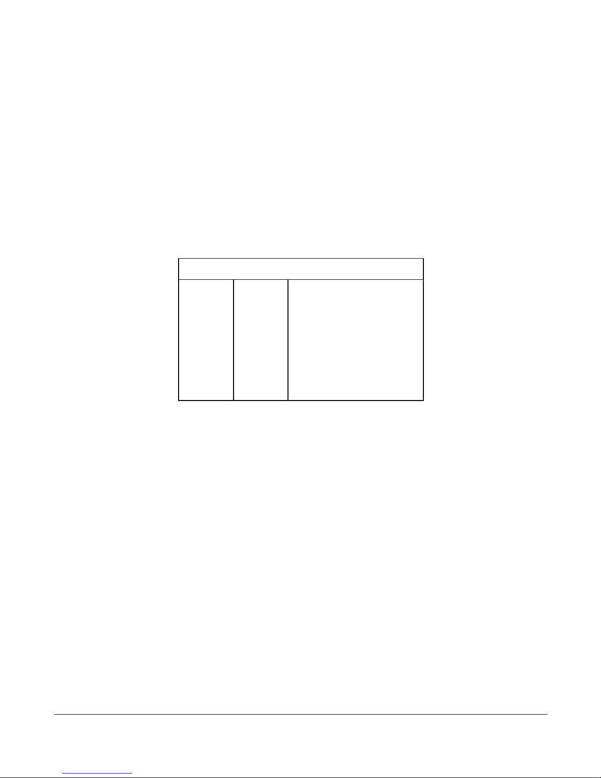
3-PIN TO 5-PIN CONVERSION CHART
If using a console with a 3-pin DMX output connector, a 3-pin to 5-pin adapter is needed. The chart below details
a proper cable conversion:
3-PIN TO 5-PIN CONVERSION CHART
Conductor
3 Pin Female (output)
5 Pin Male (Input)
Ground / Shield
Pin 1
Pin 1
Data ( - ) signal
Pin 2
Pin 2
Data ( + ) signal
Pin 3
Pin 3
Do not use
Do not use
Do not use
Do not use
SETTING UP A DMX SERIAL DATA LINK
1. Connect the (male) 5-pin connector side of the DMX cable to the output (female) 5-pin connector of the DMX
console.
2. Connect the opposite end of the cable (female) to the input connector of the fixture consisting of a (male) 5-pin
connector.
3. Proceed to connect from the fixture output as stated above to the input of the following fixture and so on.
4. Continue linking until the last fixture is connected in your DMX chain.

SoLED W840 User Manual Version 4.1 051915 PRELIMILARY 7
FIXTURE MOUNTING / RIGGING
Orientation
Solaris LED fixtures may be mounted in any position. Always make sure there is adequate room for ventilation.
Do not obstruct the unit’s vents.
Support Stand
Always use a professional stand rated to support weight greater than the SoLED weight (4.77 lb. / 2.15
kg). Attach a TVMP spigot to the yoke of the SoLED and mount on the stand.
Rigging – Always consult a qualified rigging specialist before suspending any fixture
overhead.
Use ProBurger® couplers or equivalent C- or O-type clamps for attaching to truss. Do not
obstruct vents. Adjust the fixture angle by loosening both knobs and tilting the fixture as
needed. After establishing the desired position, retighten both knobs.
Always use safety cables!
When selecting installation location, consider routine maintenance.
Never mount fixture where it will be exposed to moisture, high humidity, extreme
temperatures, or restricted ventilation.
3. OPERATING INSTRUCTIONS
CONTROL PANEL NAVIGATION
Access control panel functions via four control panel buttons surrounding the LCD display. Buttons are indicated
by a concentric circle.
The control panel LCD display shows the menu items selected from the menu map (page 8). When a menu
function is selected, the display will show the first available option for the selected menu function. To select a
menu item, press <MENU>.

SoLED W840 User Manual Version 4.1 051915 PRELIMILARY 8
Press and hold the <MENU> button to access the top level menu items.
Use the <UP>and <DOWN> buttons, located to the right of the LCD screen, to navigate the menu map and
menu options. Press the < > button to access the menu function currently displayed, or to enable a menu
option. To return to the top of the menu map or menu without changing the value, press the < X > button.
MAIN MENU FUNCTIONS:
DMX Address – DMX Address selection menu
Control – Control mode selection menu
Manual – Gives manual control of device
Measure – Shows system measurements
Thermometer – Shows current temperature
During normal operation the control panel LCD display indicates the DMX start address of the SoLED. When
the DMX signal is not connected, or if the Solaris LED is not receiving a DMX signal, the SoLED blinks RED.

SoLED W840 User Manual Version 4.1 051915 PRELIMILARY 9
MENU MAP
Level 1
Level 2
Level 3
Notes
DMX
Address
1-512
Set the DMX start address
Control
In this menu function fixture control options can be
selected
DC
DMX mode is set to 1 channel (Intensity)
F3
DMX mode is set to 3 channels (Int+Dur+Rate)
F4
DMX mode is set to 4 channels
(Int+Dur+Rate+Eff)
Manual
Manual control of fixture effects. Stand-alone
function.
Int
0-255
Set strobe intensity
Dur
0-255
Set strobe duration
Rate
0-255
Set strobe rate
Eff
0-255
Set strobe effects
Measure
Displays system measurements (input voltage,
frequency, temperate, etc.)
Thermometer
Shows current temperature of device
DURATION TIME: RATE TIME RELATION.
SoLED W840 User Manual Version 4.1 051915 PRELIMILARY 10
FUNCTION DESCRIPTION
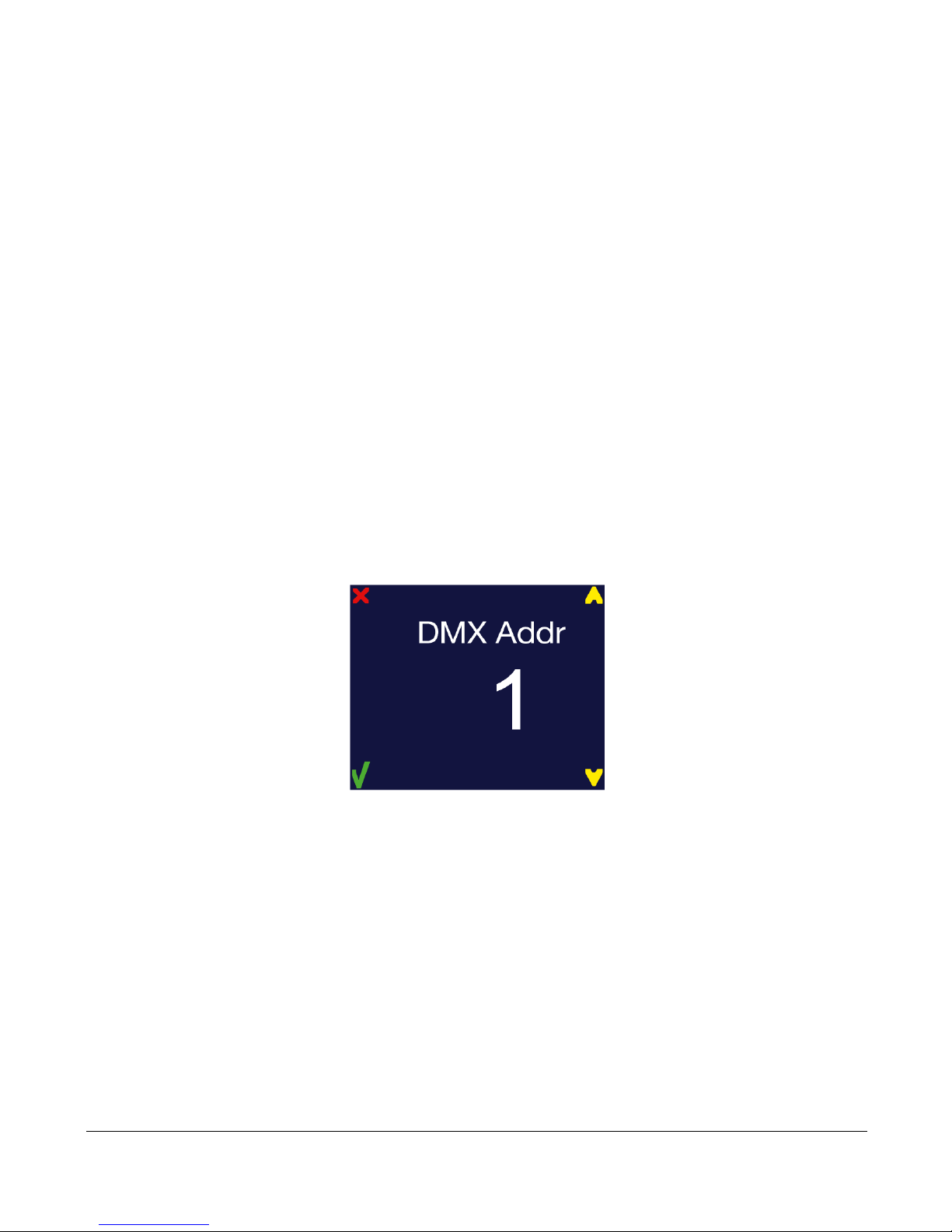
DMX ADDRESS
To set the required DMX Address, you must:
1) Press and hold <MENU> button to open the Main Menu.
2) Use <UP>and <DOWN> buttons to find the DMX Address submenu.
3) Press < > button to access the DMX Address value change submenu.
4) Use <UP> and <DOWN> buttons to set necessary DMX Address value (e.g. DMX Address 1).
5) Use < > button to confirm new DMX Address.
6) When the new DMX Address is confirmed return to Main Menu. Press < X > button to return fixture at
the work state.
7) At work state, control panel display shows current DMX Address, in this case 1.

SoLED W840 User Manual Version 4.1 051915 PRELIMILARY 11
CONTROL
SoLED has three control modes:
DC (Intensity control only at 2400Hz flicker-free mode)
F3 (Intensity, Duration, Rate)
F4 (Intensity, Duration, Rate, Effects – includes DC mode in Effects).
To switch between SoLED control modes, do following:
1) Press and hold <MENU> button to open the Main Menu.
2) Use <UP> and <DOWN> buttons to find the Control submenu and press < > button.
3) Now the Control submenu is opened
5) Choose one of these three operating modes.
6) When new mode is confirmed using the < > button, you return to Main Menu. Press < X > button to
return the fixture to work state.
7) At the work state, the control panel display shows current DMX Address, in this case 1.
STROBE MODES
Three or four channels control strobe parameters:
Strobe Intensity
Strobe Duration
Strobe Rate
Strobe FX (only in F4, 4-channel mode)

SoLED W840 User Manual Version 4.1 051915 PRELIMILARY 12
Channel
DMX
Values
Percent
Strobe Function
First
Strobe
Channel
Flash intensity
0 - 5
0 - 1
Blackout (0-7 DMX in DC Mode)
6 - 255
2 - 100
Intensity level (8-255 in DC Mode)
Second
Strobe
Channel
Flash duration
0 - 255
0 - 100
0 - 650ms (50Hz AC)
0 - 530ms (60Hz AC)
Third
Strobe
Channel
Flash rate
0 - 5
0 - 1
No flash
6 - 255
2 - 100
0.5 - 25 Hz (50Hz AC)
0.6 - 30 Hz (60Hz AC)
Fourth
Strobe
Channel
Flash effects
(Only on
F4 mode)
0 - 5
0 - 2
No effect
6 - 42
16-Mar
Ramp up
43 - 85
17 - 33
Ramp down
86 - 128
34 - 50
Ramp up – down
129 - 171
51 - 67
Random
172 - 214
68 - 84
Lightning
215 - 250
85 - 97
Spikes
251 - 255
98 - 100
DC Mode Override- v.4.0 software or higher
SPECIAL EFFECTS DESCRIPTIONS:
Ramp up: Light gradually increases in intensity, then blacks out.
Ramp down: Light flashes to full intensity, then gradually fades.
Ramp up-down: Light gradually increases and decreases.
Random flash: Light flashes randomly at variable rate and intensity. Multiple units flash independently.
Lightning: Flashes simulate lightning. Duration is not adjustable.
Spikes: Lamp remains dimly illuminated between flashes. Set flash intensity, duration, and rate as
normal.

SoLED W840 User Manual Version 4.1 051915 PRELIMILARY 13
DC MODE Override: Lamp changes to 2400Hz flicker-free mode. This mode uses the intensity
channel of F4 mode to scale the intensity from 0 – 100%. Strobe Rate, Duration, and Effects are
bypassed. Fixture will remain at a constant intensity unless it senses a thermal limit being hit and will
throttle itself down in intensity back to operational specs. This mode will exhibit stepping, especially in
the lower range of the intensity channel due to the nature of the near pure-DC operation of the leds.
NOTE: If fixture senses over-limit thermal operation, smart-limiting activates and throttles the fixture
down to safe operating levels. The fixture allows full output bursts if the temperature is within operating
specifications.
MANUAL MODE
Manual Mode allows control of SoLED without a controlling device. In this menu, manually select strobe
intensity, duration, and rate between strobe and other effects (see page 12). Manual Mode is a stand-alone
mode; values are saved if power is interrupted. “Reset” will clear Manual Mode values.
Manual function includes four settings:
Int (intensity of strobe)
Dur (duration of strobe)
Rate (duration between flashes)
Eff (special effect channel (see table on page 14)
1) Press and hold <MENU> button to open the Main Menu.
2) Use <UP> and <DOWN> buttons to find the Manual submenu and press the < > button.
3) Manual Mode submenu will open.
Int (Intensity)
Dur (Duration)
Rate
Eff (Effects, FX)
4) Manual Mode submenu will open.
Int (Intensity)
Dur (Duration)
Rate
Eff (Effects(FX)
SoLED W840 User Manual Version 4.1 051915 PRELIMILARY 14
Settings values are converted to percentages (e.g. 255=100%; 0=0%)
FX effects have specific values:
Flash effects (FX)
0 - 5
0 - 2
No effect
6 - 42
3 - 16
Ramp up
Ramp down
43 - 85
17 - 33
Ramp up
Ramp down
Ramp up-down
86 - 128
34 - 50
129 - 171
51 - 67
Random
172 - 214
68 - 84
Lightning
215 - 251
252 - 255
85 - 97
98 - 100
Spikes
DC mode Override
To edit values, do following:
Use <UP> and <DOWN> buttons to select the strobe function to be modified.
Press < > button.
Press <UP> and <DOWN> buttons to modify the value (255=100%; 0=0%; for FX see above).
Repeat with all settings until desired effect is achieved.
Press < > button once more to exit editing the current value and to lock in the desired value
Follow the above steps to edit other values.
Press < X > button to exit Manual Mode.

SoLED W840 User Manual Version 4.1 051915 PRELIMILARY 15
DURATION TIME: RATE TIME RELATION.
MEASURE
This submenu shows all possible sensor values.
1) Press and hold <MENU> button to open the Main Menu.
2) Use <UP> and <DOWN> buttons to find the Measure submenu and press < > button.
Indicated are Input voltage (Uin); frequency (Frq); temperature (T) / power (P); and power limiting (Plim). If
SoLED overheats, output power will automatically decrease.

SoLED W840 User Manual Version 4.1 051915 PRELIMILARY 16
3) To change temperature scale from Celsius to Fahrenheit, press <UP> or <DOWN> buttons.
THERMOMETER
1) Press and hold <MENU> button to open the Main Menu.
2) Use <UP> and <DOWN> buttons to find the Thermometer submenu and press select button.

SoLED W840 User Manual Version 4.1 051915 PRELIMILARY 17
This setting shows operating temperature of the device. To change temperature readings between Celsius and
Fahrenheit, press the <UP> and <DOWN> buttons.
4. APPENDIX
BASICS OF DMX CONTROL
There are 512 channels in a DMX-512 connection. Channels may be assigned in any manner. A fixture capable
of receiving DMX-512 will require one or a number of sequential channels. The user must assign a starting
address on the fixture that indicates the first channel reserved in the lighting console. There are many different
types of DMX controllable fixtures and they all may vary in the total number of channels required. Choosing a
start address should be planned in advance. Channels should never overlap. If they do, this will result in erratic
operation of the overlapping fixtures. You can however, control multiple fixtures of the same type using the same
starting address as long as the intended result is that of unison movement or operation. In other words, the
fixtures will be slaved together and all will respond identically.
DMX fixtures are often designed to receive and transmit data through a DMX daisy-chain. A DMX daisy-chain is
where the DMX OUT of one fixture connects to the DMX IN of the next fixture. The order in which the fixtures
are connected is not important and has no effect on how a lighting console communicates to each fixture. Use
an order that provides for the easiest and most direct cabling. Connect fixtures using shielded two conductor
twisted pair cable such as ProPlex® DMX with 5-pin XLR male to female connectors. The shield/ground is pin 1,
while pin 2 is Data Negative (D-) and pin 3 is Data positive (D+). Pins 4 and 5 are not used according to the
DMX-512 standard.
GENERAL MAINTENANCE
To maintain optimum performance and minimize wear fixtures should be cleaned frequently. Usage and
environment are contributing factors in determining frequency. As a general rule, fixtures should be cleaned at
least twice a month. Dust build up reduces light output performance and can cause overheating. This can lead
to reduced lamp life and increased mechanical wear. Be sure to disconnect power to the fixture before
conducting maintenance.
Unplug fixture from power. Use a vacuum or air compressor and a soft brush to remove any dust
on external vents and internal components. Clean all glass when the fixture is cold with a mild solution of glass
cleaner or Isopropyl Alcohol and a soft lint free cotton cloth or lens tissue. Apply solution to the cloth or tissue
and drag dirt and grime to the outside of the lens. Gently polish optical surfaces until they are free of haze and
lint.

SoLED W840 User Manual Version 4.1 051915 PRELIMILARY 18
The cleaning of internal and external optical lenses and/or mirrors must be carried out periodically to optimize
light output. Cleaning frequency depends on the environment in which the fixture operates: damp, smoky or
particularly dirty surroundings can cause greater accumulation of dirt on the unit’s optics. Clean with soft cloth
using normal glass cleaning fluid. Always dry the parts carefully. Clean the external optics at least every 20
days. Clean the internal optics at least every 30 to 60 days.
LIMITED WARRANTY
Solaris LED fixtures (the Product) are warranted by TMB against defective materials or workmanship for a
period of two (2) years from the date of original sale by TMB.
TMB’s warranty shall be restricted to the repair or replacement of any part that proves to be defective and for
which a claim is submitted to TMB before the expiration of the applicable warranty periods.
This Limited Warranty is void if the defects of the Product are the result of:
Opening the casing, repair, or adjustment by anyone not specifically authorized by TMB
Accident, physical abuse, mishandling, or misapplication of the product.
Damage due to lightning, earthquake, flood, terrorism, war, or act of God.
TMB will not assume responsibility for any labor expended, or materials used, to replace and/or repair the
Product without TMB’s prior written authorization. Any repair of the Product in the field, and any associated labor
charges, must be authorized in advance by TMB. Freight costs on warranty repairs are split 50/50: Customer
pays to ship defective product to TMB; TMB pays to ship repaired product, ground freight, back to Customer.
This warranty DOES NOT cover consequential damages or costs of any kind.
A Return Merchandise Authorization (RMA) Number must be obtained from TMB prior to return of any defective
merchandise for warranty or non-warranty repair. For all repairs please contact TMB Tech Support Repair using
the contact information below or email TechSupportRepa[email protected]om.
527 Park Ave., San Fernando, CA 91340
Tel: +1 818.899.8818
Fax: +1 818.899.8813
www.tmb.com
RETURN PROCEDURE
Returned merchandise must be sent prepaid and in the original packing, call tags will not be issued. Package
must be clearly labeled with a Return Merchandise Authorization Number (RMA #). Products returned without
an RMA # will be refused. Please contact TMB and request RMA # prior to shipping the fixture. Be prepared to
provide the model number, serial number and a brief description of the cause for the return. Be sure to properly
pack fixture, any shipping damage resulting from inadequate packaging is the customer’s responsibility. TMB
reserves the right to use its own discretion to repair or replace product(s). As a suggestion, proper UPS packing
or double-boxing is always a safe method to use.
Note: If you are given an RMA number, please include the following information on a piece of paper
inside the box:
1) Your name
2) Your address
3) Your phone number
4) The RMA no.
5) A brief description of the symptoms

SoLED W840 User Manual Version 4.1 051915 PRELIMILARY 19
CONTACT INFORMATION
GENERAL INFORMATION TMB
US Phone: +1 818.899.8818
Fax: +1 818.899.8813
UK Phone: +44 (0)20.8574.9700
Fax: +44 (0)20.8574.9701
web: www.tmb.com
24/7 TECHNICAL SUPPORT TMB
US/Canada: 1 877.TMB.DUDE (+1 877.862.3833)
Toll-free UK: 0800.652.5418
International: +1 818.794.1286
DIMENSIONAL DRAWING

SoLED W840 User Manual Version 4.1 051915 PRELIMILARY 20
TECHNICAL SPECIFICATIONS – SOLARIS LED SOLED, 840W STROBE
WEIGHT & DIMENSIONS
LENGTH ....................................................................................................... 14.2 IN / 360 MM
WIDTH ............................................................................................................. 3.7 IN / 95 MM
HEIGHT .......................................................................................................... 31.5 IN / 80 MM
WEIGHT ....................................................................................................... 5.6 LB. / 2.56 KG
POWER
OPERATING VOLTAGE ....................................................................... 100-240VAC, 50/60 HZ
FUSE ................................................................................................ 12A, 250V SLOW-BLOW
PEAK POWER ............................................................................................................... 840W
POWER CONNECTORS .................................................................... IN POWERCON 20A BLUE
LIGHT SOURCE
LED COUNT .......................................................................................... 84 CREE XP-L LED'S
COLORS ..................................................................................................................... WHITE
COLOR TEMPERATURE ............................................................................................... >5700K
BEAM SPREAD ............................................................................................................... 100°
THERMAL
MAX. AMBIENT TEMPERATURE ..................................................................................... +40°C
MIN. AMBIENT TEMPERATURE ....................................................................................... -20°C
COOLING ...................................................................................................... CONVECTIONAL
CONTROL & PROGRAMMING
CONTROL .................................................................. DMX-512A WITH RDM, MANUAL MODE
DMX CHANNELS ........................................................................................................... 1,3,4
DMX INPUT........................................................................ LOCKING 5-PIN XLR MALE SOCKET
DMX OUTPUT ............................................................... LOCKING 5-PIN XLR FEMALE SOCKET
DMX PIN CONFIG ............................................ PIN 1 SHIELD, PIN 2 (-), PIN 3 (+), PINS 4 & 5 N/A
WARRANTY INFORMATION
WARRANTY ................................................................................... 2-YEAR LIMITED WARRANTY
Table of contents
Other Solaris Lighting Equipment manuals


