SOLARJACK SDS - REV 4-92 User manual

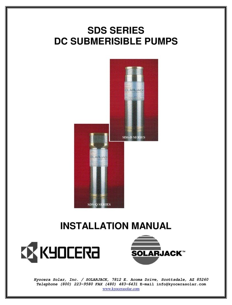
SDS SERIES
DC SUBMERISIBLE PUMPS
REBUILD MANUAL
Kyocera Solar, Inc. / SOLARJACK, 7812 E. Acoma Drive, Scottsdale, AZ 85260
Telephone (800) 223-9580 FAX (480) 483-6431
www.kyocerasolar.com

12/06/99 2
SDS PUMP REBUILD INSTRUCTIONS
Rev.4/92
1. Remove cable guard screws (Item 1).
2. Remove 1/8” pipe plug (Old Style) or 3/8” NC set screw (New Style)
(Item 5) using a 3/16" hex wrench. WARNING: PUMP HOUSING MAY BE UNDER
HIGH PRESURE. USE EXTREME CAUTION IN REMOVING END CAP PLUGS AND END CAP
SCREWS.
3. Remove the two socket head screws (Item 26) from end cap (Item 6) using
a 5/32" hex wrench.
4. Clamp the pump in the puller and screw the proper threaded mandrel in
the end cap.
5. Pull the end cap out of the stainless housing. If the brass ends seem to
be stuck, warm the stainless housing slightly with a small propane
torch, being careful not to overheat and warp the housing. As the end
cap (Item 8) comes out, disconnect the two motor wires plugged into the
end cap.
6. With the end cap removed from the housing, turn the pump around, screw
the appropriate mandrel into the discharge head, and remove the pump
assembly from the stainless housing.
7. Remove the four socket head screws (Item 25) from the discharge head
using a 5/32", hex wrench.
8. Remove the bypass valves and springs (Items 19 & 20), suction 5creen
(Item 24), check valve assembly (Item 21), and gasket (Item 22) from the
discharge head. Note: Check valve removal may require a lite tap with a
blunt tool through the discharge opening.
9. Remove the two motor adapter screws (Items 4) using a 5/32”, hex wrench.
Remove the set screw from the cam assembly (Item 13) using a long 1/8”,
hex wrench. This wrench must be inserted through the hole in the side of
the motor adapter (Item 16). Before inserting the wrench, visually align
the set screw with the hole by turning the motor adapter while holding
the motor.
10. Pull the motor adapter and cam assembly away from the motor, remove the
two piston screws (Item 12), and then the cam assembly (Item 13).
11. Discard the support collars (Item 14), O-ring6 (Items 9), diaphragm (Item
17), check valve (Item 23), and gasket (Item 22).
12. Clean and inspect all remaining parts and make sure that the electrical
studs protruding from the epoxy in the end cap are in good condition and
the epoxy is still hard.

12/06/99 3
SDS PUMP REBUILD INSTRUCTIONS
ASSEMBLY
1. Set the brass pistons (Items 18) flat side down on the pump assembly
plate, positioning the two holes over the locating studs.
2. Place the diaphragm (Item-17), with the offsets up, over the pistons
locating the piston shafts through the two holes.
3. On an SDS-D-128 use only the white santoprene diaphragm. 0n an SDS-D-228
use only the black EPDM diaphragm and install the Teflon wear washer
(Item 15) around the piston shaft. CAUTION- NEVER USE ANY TYPE, OF
GREASE ON EITHER DIAPHRAGM, IT MAY CALUSE DIAPHRAGM FAILURE.
4. Slip the support collars (Item 14) over the shafts with the radius side
toward the diaphragm.
5. Set the motor adapter (Item i6) face down over the diaphragm assembly
allowing the piston to protrude through the two holes being careful not
to nick or cut the diaphragm.
6. Put the set screw into the cam and insert the cam assembly (Item 13) over
the piston shaft making sure the piston shafts fit into the cam plate
holes.
7. Insert the two piston screw (Item 12) through the cam assembly, and
tighten with a 5/32”, hex wrench to 60 inch lbs. of torque. (Be careful
not to allow the pistons to slip off the locating studs while tightening
the screws.) Each screw should be tightened a little at a time
alternating between each side. This will pull both pistons into alignment
before either piston clamps the diaphragm.
8. Place the motor on the assembly board with the shaft up. Turn the motor
shafts until the flat side faces you.
9. Coat the inside of the cam hole and the outside of the motor shaft with
silver anti-seize (NAPP. part no. 765-1674, is recommended).
10. Insert a long 1/8”, hex wrench through the hole in the motor adapter and
into the cam set screw.
11. Slip the cam assembly over the motor shaft aligning the set screw to the
center of the flat on the shaft. As the cam assembly is inserted over the
motor shaft tighten the set screw until it lightly touches the motor
shaft and then back it off 1/8 turn. Continue installing the cam assembly
until the motor adapter butts up to the motor. Then push on the pistons
until the cam assembly bottoms on the motor shaft. While holding the
piston down firmly, tighten the set screw.

12/06/99 4
12. With the motor assembly still on the board, gently lift the diaphragm up
on each end and insert one stainless washer (Item 6) in each motor adapter
hole.
13. Insert the two 10-22 X 2” motor adapter screws (Item 4) into the motor
adapter holes. Rotate the motor adapter slowly until screws "drop" into
place. Tighten the screws while alternating between the two, to 50 inch
lbs. of torque.
14. Lay the discharge head (Item 24) top side down on a flat surface and
install the suction screen (Item 23) with the welded seam placed between
the two cable guard screw holes.
15. Install the check valve seal (Item 22) and check, valve (Item 21) into the
discharge head. Make sure the check valve assembly is flush with the
discharge head. Turn the discharge head over and insert the four washers
(Item 6) and the 10-32 X 1 1/2" stainless screws (Items 25) into the 4
countersunk holes.
16. Install the relief valves (Items 20) into the two springs (Items 19) until
seated. With the motor and motor adapter still on the assembly board,
insert the two relief valve spring assemblies (Items 19 & 20) over the
small studs on the diaphragm with the relief valves pointing up.
17. With the motor assembly still held in a vertical position, install the
discharge head on the motor adapter while carefully guiding the relief
valves into the holes in the check valve assembly. Make sure the relief
valve springs stay on the small studs and the relief valve is seated in
the check valve assembly.
18. While holding the discharge 'head in position tighten the four screws a
little at a time, jumping to opposite sides, to 45 inch lbs. of torque.
19. Install pumps on flow and amp test fixture and run for 20 minutes and then
check the flow and motor current to see if they are within specifications.
(If test fixture is available.)
20. Set the pump with the discharge end facing down an a flat table.
21. Install the three o-rings (Item 9) onto the motor adapter and lightly
lubricate with a non-outgasing food grade grease. (Swepco #115 or
petroleum jelly)
22. Lightly grease the inside of both ends of the stainless housing about one
inch deep and slip it over the pump assembly, with the longer inside bore
down, until it rests on the O-rings. With a small block of wood or other
soft flat object push the housing down over the O-rings until it touches
the brass lip on the motor adapter.
23. Screw a 10-12 X 3" stud into one of the coupling nuts (Item 10) on the
back side of the motor. This is used as a guide when installing the end
cap assembly.
24. Install the O-rings on the end cap assembly (Item 8) and lightly grease
the O-rings.

12/06/99 5
25. Connect the motor leads to the electrical studs on the inside of the end
cap. (Make sure the positive red wire lead connects to the red wire side,
(yellow on two-wire pumps). Before seating end cap in housing, be sure
that the terminals on the wires are tight on the end cap electrical studs.
Slide the end cap over the guide stud, making sure that head lead wires
are not pinched between the end cap coupling nuts. Make sure the cable
guard screw holes are on the same side as the screw in the discharge head.
26. With a small block of wood push the end cap down inside the housing until
it butts up against the brass cap lip
27. Remove the guide stud, insert the two 10-32 X 2" (short motor) or 10-32 x
1 1/2" (long motor) end cap screws (Items 26), washers (Items 6) and new
O-rings (Items 7). Apply a small amount of non-outgasing silicone sealant
around the o-ring. CAUTION: DO N0T USE ANY SILICONE SEALANT THAT RAS AN
ODOR. (DOW CORNING 3145 RTV ADHESIVE / SEALANT IS RECOMENDED). Tighten the
two screws to 40inch-lbs. of torque.
28. Install the end cap plug and tighten with a 3/16”, hex wrench. A non
outgasing anti-seize grease should be used on the threads.
29. Install pumps on final flow and amp test fixture and run for 20 minutes.
Retest the pump for flow and current. (If test fixture is available)
30. Install the cable guard over the motor lead using the four screws (Items
1)
31. Re-torque the four discharge head acres (Item 25), to 45 inch pounds of
torque. Never retorque the end cap screws if a silicone sealant is used.

12/06/99 6

12/06/99 7

12/06/99 8

12/06/99 9

12/06/99 10
This manual suits for next models
6
Other SOLARJACK Water Pump manuals
Popular Water Pump manuals by other brands

Pentair
Pentair DELTA ENVIRONMENTAL D1C20-21 Series Installation and service manual

Viking pump
Viking pump 493 Series Technical & service manual

Krautzberger
Krautzberger MP-520 operating instructions

Bestway
Bestway 62140 owner's manual

HARBEN
HARBEN E Series Operation & maintenance manual

Pondmaster
Pondmaster WFP1900 Care and operating instructions

Zoeller
Zoeller 2701-0005 Quick reference guide

Annovi Reverberi
Annovi Reverberi AR 320 bp Twin instruction manual

DAB
DAB MICRA HS Series Installation and operating instructions

Cembre
Cembre CPE-1 Operation and maintenance manual

SHURflo
SHURflo 8025-933-399 Installation and operation manual

MULTIQUIP
MULTIQUIP MQ ST1 Operation and parts manual