Solaronics AC Series Owner's manual

SOLARONICS Chauffage SAS. 78 rue du Kemmel –CS 20302 –F-59429 ARMENTIERES
Phone : +33 3.20.10.59.59 - Fax : +33 3.20.35.57.22
www.solaronics.com
CONDENSING WARM AIR HEATER TECHNICAL INSTRUCTIONS –NT12009I-GB –18/12/2017
- 2 -
Index
1. Introduction................................................................................................................................................... 3
1.1. Symbols ................................................................................................................................................. 3
1.2. Abbreviations ......................................................................................................................................... 3
1.3. General.................................................................................................................................................. 3
1.3.1. Manufacturer’s liability............................................................................................................................ 3
1.3.2. Installer’s liability .................................................................................................................................... 4
1.3.3. User’s liability ......................................................................................................................................... 4
1.4. Certifications .......................................................................................................................................... 4
2. Safety instructions and recommendations ................................................................................................ 5
2.1. Safety instructions.................................................................................................................................. 5
2.2. Recommendations................................................................................................................................. 6
3. Description.................................................................................................................................................... 6
3.1. Operating principle................................................................................................................................. 6
3.1.1. Boiler..................................................................................................................................................... 6
3.1.2. Ventilation............................................................................................................................................. 7
3.1.3. Heat transfer fluid loop........................................................................................................................ 7
3.1.4. Regulation ............................................................................................................................................ 7
3.2. Main components................................................................................................................................... 8
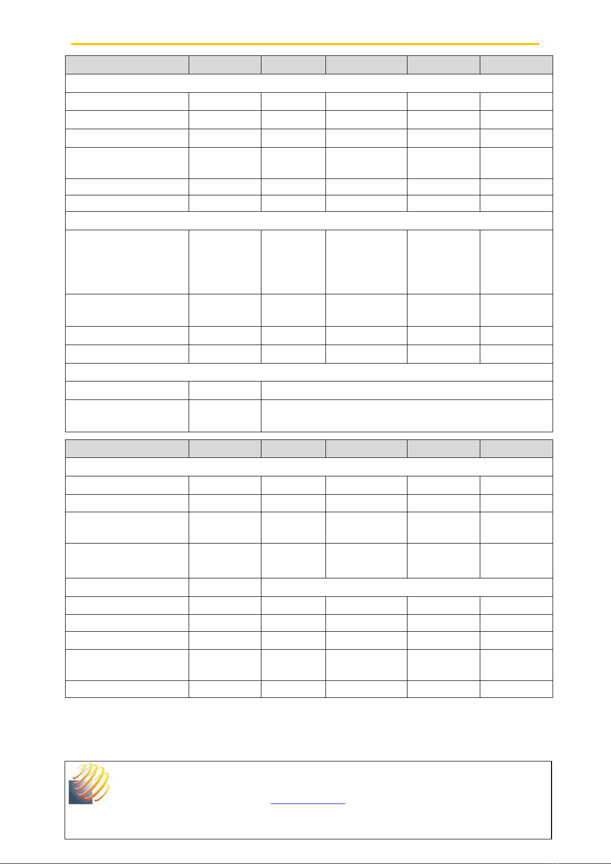
3.3. Technical characteristics........................................................................................................................ 9
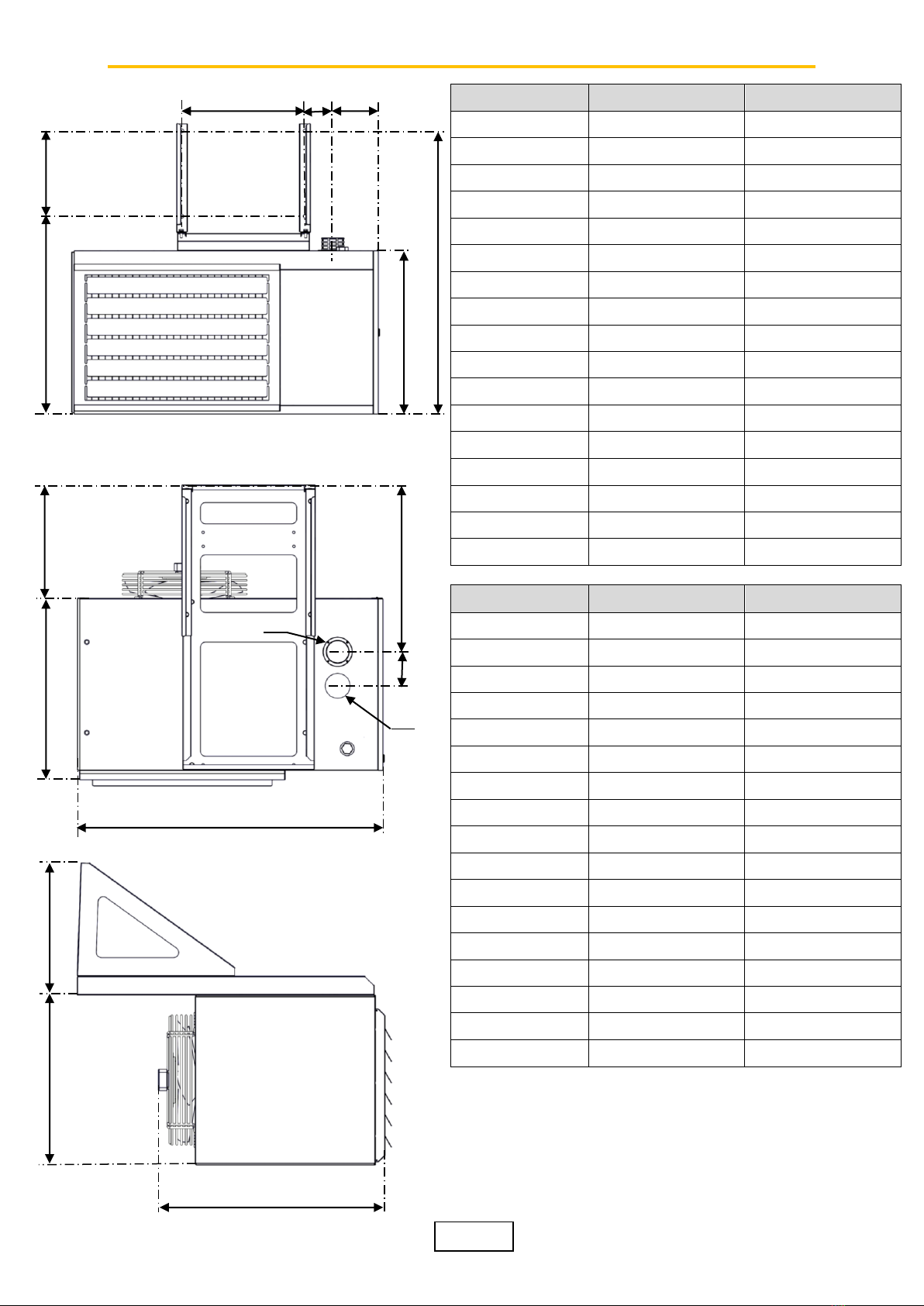
3.4. Overall dimensions............................................................................................................................... 10
4. Appliance installation................................................................................................................................. 11
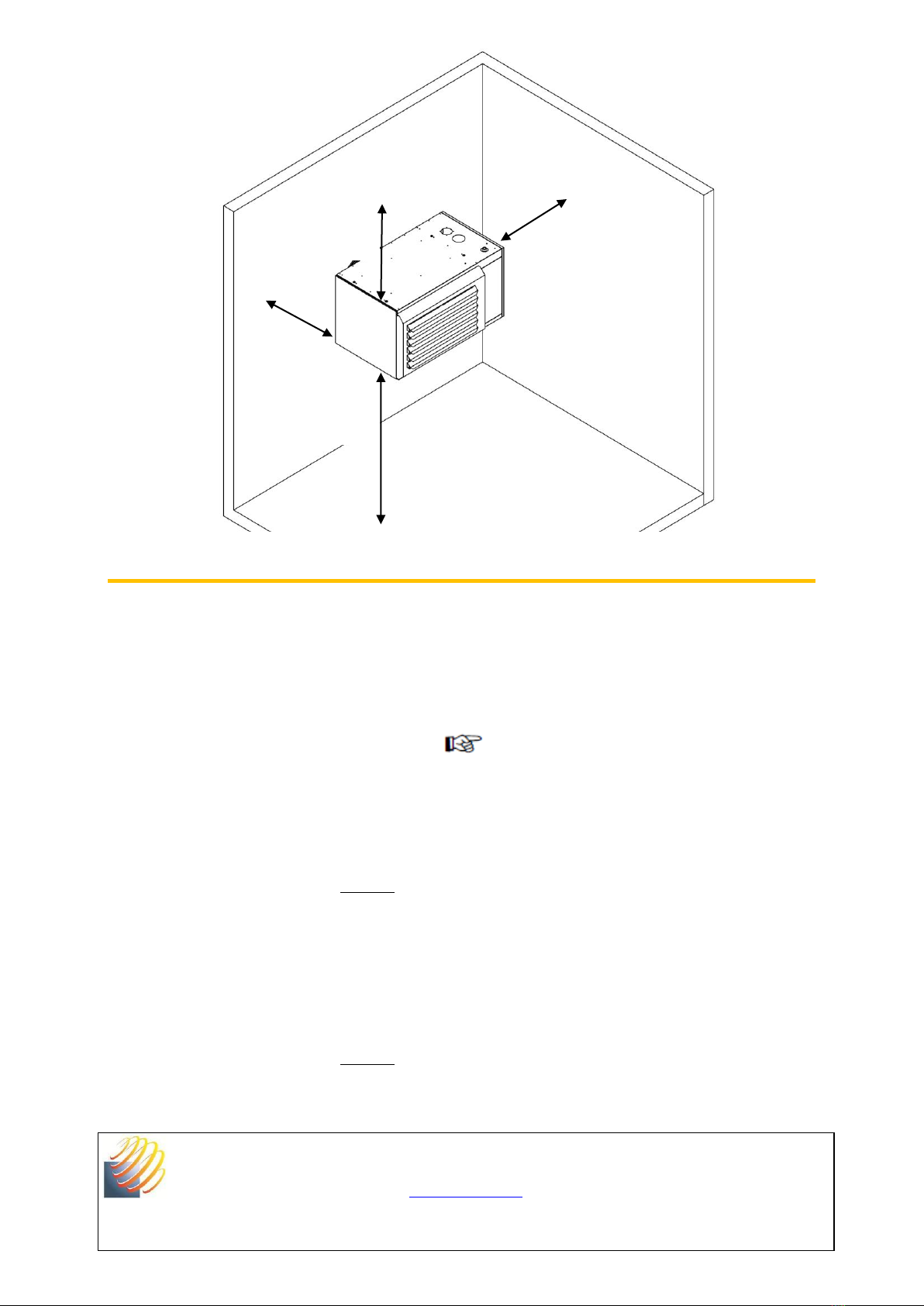
4.1. General rules........................................................................................................................................ 11
4.2. Fixing the appliance............................................................................................................................. 13
4.3. Connecting flue pipes........................................................................................................................... 14
4.3.1. B23 type evacuation flue connection.................................................................................................... 16
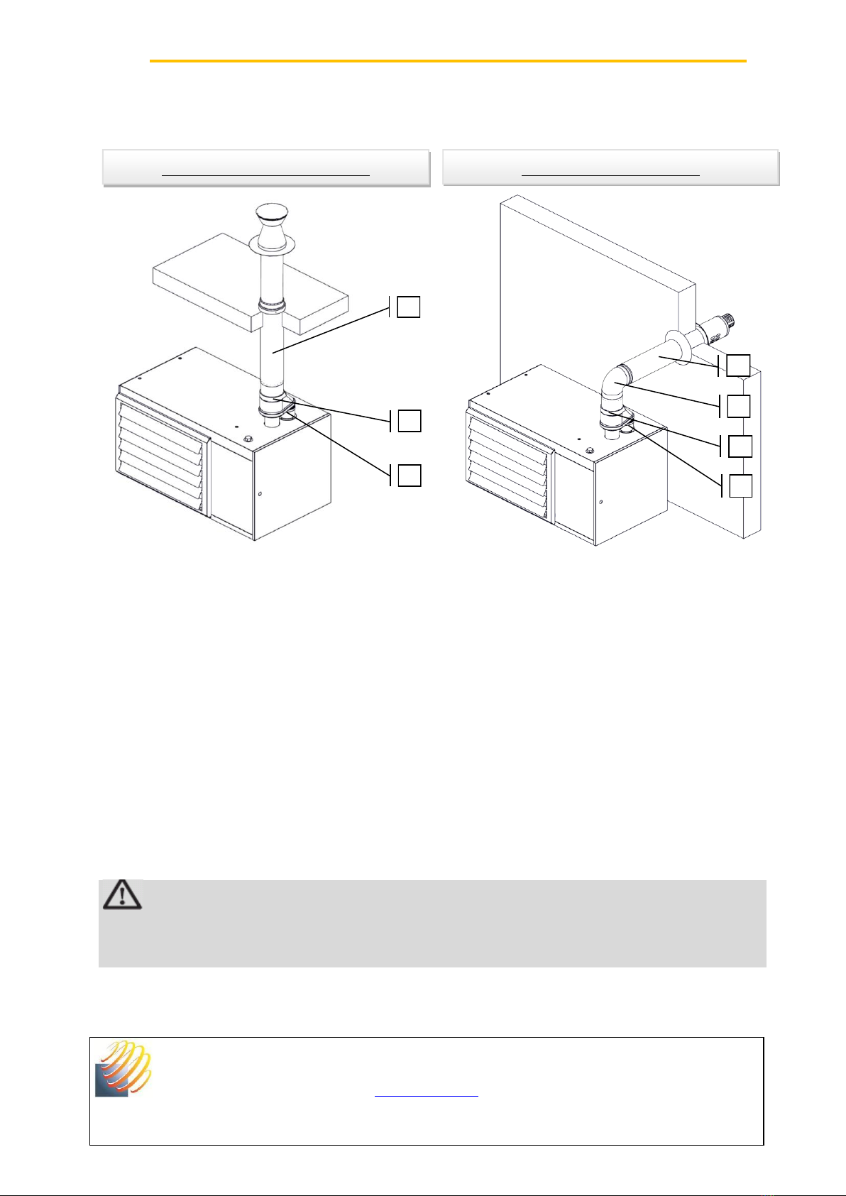
4.3.2. C33 and C13 type evacuation flue connection..................................................................................... 17
4.3.3. C53 type evacuation flue connection ................................................................................................... 18
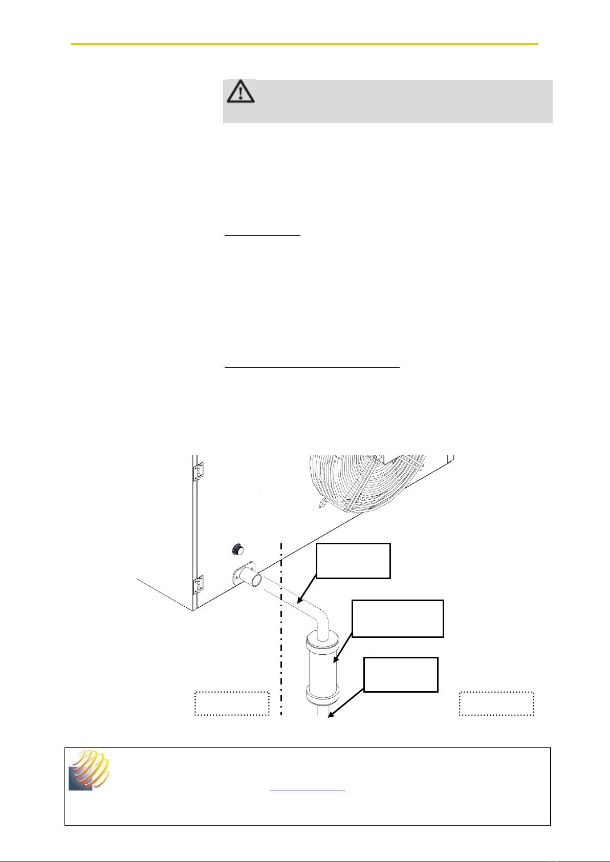
4.4. Condensate drain................................................................................................................................. 19
4.5. Gas connection.................................................................................................................................... 20
5. Temperature control –Electric connection.............................................................................................. 22
5.1. Temperature control............................................................................................................................. 22
5.2. Electric connection............................................................................................................................... 23
5.2.1. Description........................................................................................................................................... 23
5.2.2. Connexion............................................................................................................................................ 25
5.2.3. Internal wiring diagram......................................................................................................................... 26
6. Commissioning........................................................................................................................................... 27
6.1. Start ..................................................................................................................................................... 27
6.2. Burner setting....................................................................................................................................... 28
7. Troubleshooting.......................................................................................................................................... 30
7.1. Troubleshooting ................................................................................................................................... 30
7.2. Spares.................................................................................................................................................. 31
8. Maintenance................................................................................................................................................ 32
9. Warranty ...................................................................................................................................................... 36

SOLARONICS Chauffage SAS. 78 rue du Kemmel –CS 20302 –F-59429 ARMENTIERES
Phone : +33 3.20.10.59.59 - Fax : +33 3.20.35.57.22
www.solaronics.com
CONDENSING WARM AIR HEATER TECHNICAL INSTRUCTIONS –NT12009I-GB –18/12/2017
- 3 -
1. Introduction
1.1. Symbols
In this manual, the warnings are used to point to specific
information. We want to ensure the user safety, to avoid any
problem and to ensure proper operation of the appliance.
WARNING
Indicates a potential hazard which can cause bodily injuries and/or
material damage
Indicates important information
Indicates a reference to other notices or other pages of
the manual.
Before installation and commissioning the device, read
carefully all manuals
1.2. Abbreviations
•PWM : Pulse Width Modulation (fans control in
variable speed)
1.3. General
1.3.1. Manufacturer’s liability
Our products are manufactured in compliance with various
applicable European directives requirements. They are thus
supplied with EC markings and all necessary documents. With our
commitment to quality products, we constantly seek to improve
them. We therefore reserve the right at any time to modify the
characteristics stated in this document.
Our liability as a manufacturer does not apply in the following
cases:
•Failure to follow operating instructions for the appliance.
•Failure to maintain or insufficiently maintain the appliance.
•Failure to follow installation instructions for the appliance.

SOLARONICS Chauffage SAS. 78 rue du Kemmel –CS 20302 –F-59429 ARMENTIERES
Phone : +33 3.20.10.59.59 - Fax : +33 3.20.35.57.22
www.solaronics.com
CONDENSING WARM AIR HEATER TECHNICAL INSTRUCTIONS –NT12009I-GB –18/12/2017
- 4 -
1.3.2. Installer’s liability
The installer is responsible for installation and first
commissioning of the device. The installer must observe the
following:
•Read and follow the instructions given in the instruction
manuals provided with the device.
•Carry out installation in accordance with the applicable
legislation and standards.
•Carry out the first commissioning and carry out all necessary
controls.
•Explain the installation to the user.
•Inform the user that he cannot make changes in the
appliance’s design and to the installation by himself. The
slightest modification (change, removal...) of security
components or parts automatically results in the appliance’s
CE marking becoming invalid.
•Alert the user about the obligation to control and maintain
the device.
•Hand all documents to the user.
1.3.3. User’s liability
To ensure correct operation of the appliance, the user must
observe the following:
•Read and follow the instructions given in the instructions
manuals provided with the device.
•Call in a qualified technician to carry out the installation and
perform the initial commissioning.
•Obtain explanations about the installation by the installer.
•Carry out checks and required maintenance.
•Keep all documents in good condition and near the
appliance.
1.4. Certifications
Appliance
Gas warm air generator, with condensation and
warm water heat exchanger
Directive
2009/142/CEE «Gas appliances»
NOx class
5 (EN 1020)
Flue type
Evacuation : B23
Sealed : C13, C33, C53

SOLARONICS Chauffage SAS. 78 rue du Kemmel –CS 20302 –F-59429 ARMENTIERES
Phone : +33 3.20.10.59.59 - Fax : +33 3.20.35.57.22
www.solaronics.com
CONDENSING WARM AIR HEATER TECHNICAL INSTRUCTIONS –NT12009I-GB –18/12/2017
- 5 -
2. Safety instructions and recommendations
2.1. Safety instructions
WARNING
The warm air heater is an energized device and must be grounded
during installation.
WARNING
It is not necessary to open the heating appliance's casing during
normal operating. This operation is needed only during installation
and/or servicing by authorised personnel.
•It is not allowed to obstruct and/or reduce the space
reserved for the room or the appliance vents,
•Do not obstruct flue pipes or air intake pipes
•Do not make any change in the settings made by the
qualified technician,
•Do not spray water on the heater, or touch this appliance
with wet body parts or bare feet,
•Do not touch the hot parts of the heating appliance, and/or
moving parts,
•Do not place or hang anything on the appliance,
•Any work on the appliance is prohibited before unplugging it
from the mains and closing the gas supply.
•Do not change the used gas type, security systems or control
settings, as this could lead to dangerous situations.
•Do not swallow the fluid
Call a qualified technician in the case of gas replacement, change of
gas pressure or modification of power supply.
If the appliance is not operated for a long period, disconnect the
power supply of the appliance. When commissioning, it is advisable
to use the service of a professional technician. Generally, all repair or
maintenance works must be carried out exclusively by authorised and
qualified personal.
Subscribing to a maintenance agreement is strongly recommended

SOLARONICS Chauffage SAS. 78 rue du Kemmel –CS 20302 –F-59429 ARMENTIERES
Phone : +33 3.20.10.59.59 - Fax : +33 3.20.35.57.22
www.solaronics.com
CONDENSING WARM AIR HEATER TECHNICAL INSTRUCTIONS –NT12009I-GB –18/12/2017
- 6 -
2.2. Recommendations
AC range condensation gas warm air heaters are engineered for
heating industrial and tertiary premises.
WARNING
Only qualified professionals are authorised to modify and install the
appliance.
•Read all instructions in order to benefit all the functions of
the appliance
•This information forms an integral part of the appliance and
must always be kept always with the appliance, even in the
event of transfer to another owner or user.
•Do not remove or cover the labels and material safety data
plates fixed to the devices. Labels and material safety data
plates must be readable throughout the device life.
•Install the device in a sufficiently ventilated room, except if it
has a sealed combustion
•Please contact us for any application other than those
described in this document
DON’Ts
•Do not install condensing warm air heaters:
oOutdoors
oIn environments with explosive risks,
oIn premises containing vapours of chlorinated
products
oIn extremely wet premises (electrical shock
hazard).
3. Description
3.1. Operating principle
AC warm air heaters are composed of condensation gas boiler and a
hot water battery positioned in the air flow, serial linked in a heat
transfer fluid loop.
3.1.1. Boiler
The low NOx pre-mixed modulating burner heats the water that
circulates through the heating body.

SOLARONICS Chauffage SAS. 78 rue du Kemmel –CS 20302 –F-59429 ARMENTIERES
Phone : +33 3.20.10.59.59 - Fax : +33 3.20.35.57.22
www.solaronics.com
CONDENSING WARM AIR HEATER TECHNICAL INSTRUCTIONS –NT12009I-GB –18/12/2017
- 7 -
Combustion air, drawn by a variable speed fan, goes through a
venturi system, which provides an air quantity proportional to the
gas flow.
The air/gas mixture is led to the burner in the centre of heating
stage, where it is burned.
Flue gases pass twice through a stainless steel exchanger, in order to
dissipate the maximum heat. This technology allows reaching a 98%
minimum efficiency at maximum power and 108 % in power
modulation.
When flue gas temperature is below the dew point, water vapour in
the flue gas condenses in the lower part of the heating body. Cooled
flue gases are evacuated through evacuation flue pipes. The
condensation water is evacuated through drain siphon.
3.1.2. Ventilation
The fan (axial models AC-H) or motor turbine (centrifuge models AC-
C) blows air through the battery to increase its temperature. This
technique allows a perfect homogeneity of the air temperature.
Unlike traditional exchanger, the partial or total reduction of the air
flow or an interruption of the power supply during operation does
not affect the appliance.
The combustion section is completely insulated from the air circuit,
which ensures that pollution of the heated air flow is impossible.
The condensing warm air heaters are equipped with a fan that meets
the requirements of the new European Directive 2009/125/EC.
Axial models are designed for direct blowing and are equipped in
standard with a horizontal louvers grid.
3.1.3. Heat transfer fluid loop
The fluid loop is achieved in copper pipes.
The tightness is maximum :
•Thanks to the serial production of the whole piping.
Especially all elbows are bent
•Thanks to the minimum number of fittings and tappings.
3.1.4. Regulation
Optimising a condensation system performance is related to its
control.

SOLARONICS Chauffage SAS. 78 rue du Kemmel –CS 20302 –F-59429 ARMENTIERES
Phone : +33 3.20.10.59.59 - Fax : +33 3.20.35.57.22
www.solaronics.com
CONDENSING WARM AIR HEATER TECHNICAL INSTRUCTIONS –NT12009I-GB –18/12/2017
- 8 -
The lower is the appliance power modulation, the more condensation
will be important.
Modulation range of AC heaters is 30% to 100% of rated power.
The heater internal PLC, combined with independent regulator,
allows continuous modulation of the thermal output between
minimum and maximum values. Modulating operation of the AC
heater guarantees perfect adaptation to the premises real needs.
3.2. Main components
1Axial fan
2PLC
3Condensing heat exchanger
4Burner control unit
5Gas valve
6Siphon and condensate drain
7Premix modulating burner
8Venturi
9Burner fan
10 Fluid flow meter
11 Fluid temperature (boiler out)
12 Safety valve
13 Fluid pressure sensor
14 Pump
15 Expansion valve
16 Louvers
17 Heat exchanger

SOLARONICS Chauffage SAS. 78 rue du Kemmel –CS 20302 –F-59429 ARMENTIERES
Phone : +33 3.20.10.59.59 - Fax : +33 3.20.35.57.22
www.solaronics.com
CONDENSING WARM AIR HEATER TECHNICAL INSTRUCTIONS –NT12009I-GB –18/12/2017
- 9 -
3.3. Technical characteristics
Warm air heater
Unit
AC-H30
AC-H40
AC-H50
AC-H70
General
Nominal heat input
kW NHV
7,7 –27
10,8 –36
12,6 –45
17 –63
Nominal heat output
kW
8,2 - 26,5
11,5 - 34,9
13,6 - 44,1
18,3 - 61,7
Efficiency at full load
%
98
98
98
98
Efficiency at minimum
load
%
108
108
108
108
Air flow
m3/h (15°C)
2700
3450
4600
5500
Tair
°C
8 –28,5
8 - 29
8 –28,2
9 - 33
Gas and flue gas data
Gas flow (15°C)
H (G20 20 mbar)
L (G25 –25 mbar)
Propane (G31 –37 mbar)
m3/h
m3/h
kg/h
2,86
3,16
2,10
3,82
4,21
2,81
4,77
5,26
3,51
6,68
7,37
4,91
Minimum fresh air flow
rate
m3/h
100
100
100
100
Condensate flow rate
litre/h
1,8
2,4
2,9
5,2
Flue gas temperature
°C
50-100
50-100
50-100
50-100
Electric data
Power supply voltage
230V 1N ~ 50Hz
Extreme working
temperatures
-15°C / +40°C
Warm air heater
Unit
AC-H30
AC-H40
AC-H50
AC-H70
General
Air supply diameter
mm
80
80
80
80
Flue pipe diameter
mm
80
80
80
80
Condensate drain
diameter
mm
32
32
32
32
Venturi ring
Diaphragm washer
White
6mm
White
6mm
Red
No
No
No
Gas connection
1/2’’ male
Fan power
W
200
200
420
520
Fan speed
rpm
1350
1350
1350
910
Electric power
W
350
350
550
765
Fluid circuit volume
(water + glycol -15°C)
litre
6,6
7,2
9,2
11,2
Weight
kg
88
99
110
135

- 10 -
3.4. Overall dimensions
Dimension
AC-H30
AC-H40
A
1080 mm
1079,5 mm
B
570 mm
624 mm
C
640 mm
640 mm
D
765 mm
765 mm
E
120 mm
120 mm
F
667 mm
667 mm
G
478 mm
478 mm
H
570 mm
654 mm
I
375 mm
375 mm
J
687 mm
737 mm
K
243 mm
243 mm
L
250 mm
250 mm
M
279,5 mm
279,5 mm
N
160 mm
161,5 mm
O
342 mm
342 mm
P (Air)
80 mm
80 mm
Q (Flue)
80 mm
80 mm
Dimension
AC-H50
AC-H70
A
1192 mm
1277 mm
B
674 mm
774 mm
C
712 mm
712 mm
D
842 mm
842 mm
E
120 mm
120 mm
F
667 mm
667 mm
G
478 mm
478 mm
H
704 mm
804 mm
I
375 mm
375 mm
J
787 mm
887 mm
K
243 mm
243 mm
L
250 mm
250 mm
M
304 mm
304 mm
N
224,5 mm
309 mm
O
342 mm
342 mm
P (Air)
80 mm
80 mm
Q (Flue)
80 mm
80 mm
A
G
F
C
D
E
H
I
J
K
L
P
Q
M
N
B
O

SOLARONICS Chauffage SA. 78 rue du Kemmel –CS20302 –F-59429 ARMENTIERES
Phone : +33 3.20.10.59.59 - Fax : +33 3.20.35.57.22
www.solaronics.com
CONDENSING WARM AIR HEATER TECHNICAL INSTRUCTIONS –NT12009I-GB –18/12/2017
- 11 -
4. Appliance installation
Installation of gas appliances must be carried out by qualified
personnel, it is determined the premises volume and location
characteristics, equipment vent or ventilation device which may be
installed on those premises.
Scope of delivery :
•Warm air heater
•Technical instructions
•Cable for power supply (1 m length)
•Gas fitting
•Gasket
Reception –Storage
The gas warm air heater is delivered on a wooden pallet, protected
by a cardboard and plastic film. It is essential to check the delivered
material status (even if the packaging is intact) and its compliance
with the purchase order.
In the event of damage or missing parts, report comments on the
carrier's receipt as accurately as possible, the words "subject to
unpacking" has no legal value, and then confirm the prejudice by
letter within 48h to the carrier. The buyer is responsible to check the
goods delivered, no appeal is possible if this procedure is not
followed.
Store the material in a clean, dry place, protected from shock,
vibration, temperature variations and a room humidity less than
90 %.
Handling
Unpack the appliance using adequate protective equipment.
Handling must be performed by a person equipped with the proper
equipment.
4.1. General rules
Condensing warm air heaters can be installed directly into the
premises to be heated.

SOLARONICS Chauffage SA. 78 rue du Kemmel –CS20302 –F-59429 ARMENTIERES
Phone : +33 3.20.10.59.59 - Fax : +33 3.20.35.57.22
www.solaronics.com
CONDENSING WARM AIR HEATER TECHNICAL INSTRUCTIONS –NT12009I-GB –18/12/2017
- 12 -
However, this facility is subject to the national security rules
depending on the fuel type used and the installation country. If in
doubt, check with safety and inspection bodies.
Ventilation :
Premises receiving gas appliances should be provided with
permanent ventilation in accordance with the applicable rules in the
country of installation.
Condensate draining:
The appliance is supplied with an integrated siphon for condensate
evacuating. The siphon is an integral part of the device, it is a safety
system component, and replacement by another type is strictly
prohibited.
The condensate drain must be in accordance with existing rules in
the heater country of installation.
Gas connection :
Before installing the appliance, it is necessary to check that the local
distribution conditions (gas type, pressure) are compatible with
settings of the device to be installed.
WARNING
Minimum distances required for appliance maintenance and safety:

SOLARONICS Chauffage SA. 78 rue du Kemmel –CS20302 –F-59429 ARMENTIERES
Phone : +33 3.20.10.59.59 - Fax : +33 3.20.35.57.22
www.solaronics.com
CONDENSING WARM AIR HEATER TECHNICAL INSTRUCTIONS –NT12009I-GB –18/12/2017
- 13 -
4.2. Fixing the appliance
To facilitate the installation, we recommend that you use our
hanging brackets. They are perfectly suited to the device and
positioned to meet the minimum distance measurements from the
wall.
Mounting: Always refer to the instructions provided with
the brackets
Before attaching the appliance, it is important to ensure the support
resistance.
Step 1 :
•Assemble the various elements constituting the bracket
•Attach the bracket to the wall with a system adapted to the
wall material: the screws size and type used must be
sufficient to support twice the heater weight.
•Perform a prior resistance test
Step 2 :
•Secure the heater in the bracket with the supplied screws,
tighten them.
200 mm
750 mm
2500 mm
300 mm

SOLARONICS Chauffage SA. 78 rue du Kemmel –CS20302 –F-59429 ARMENTIERES
Phone : +33 3.20.10.59.59 - Fax : +33 3.20.35.57.22
www.solaronics.com
CONDENSING WARM AIR HEATER TECHNICAL INSTRUCTIONS –NT12009I-GB –18/12/2017
- 14 -
Step 3 :
•Open the front grid louvers, at least at 45° to allow hot air
diffusion.
4.3. Connecting flue pipes
The flue systems represented in this manual are those commonly
used in the market. However, some of them are not usable in all
countries. It is up to the installer or the building owners to ensure
that the chosen flue system complies with the local installation rules.
Connection of the flue pipe/air supply pipe, can be achieved:
•with combustion air supply sealed with respect to the
premises (C type)
•with combustion air drawn from inside the premises (B type)
The warm air heater is certified for : C13-C33-C53-B23.
Flue pipes, terminals and flue elements must be manufactured from
a material resistant to condensate contained in cold flues, between
50 and 100 °C, resulting from condensation. Only polypropylene PP
or stainless steel 316 ducts are allowed.
Flue pipes, terminals and accessories used must compulsorily
be approved, use only suction and discharge terminals referenced by
SOLARONICS CHAUFFAGE, the use of non-approved equipment
results in cancelling of the warranty.
Mounting female flange of combustion air intake
The heaters are supplied with a combustion air intake (Figure 1).
Ensure adequate ventilation of the premise, the fresh air intake
required for combustion must be at least 100 m³/h per appliance.
For a sealed installation, it is necessary to mount the provided
sealed adaptor on the appliance top (Figures 2 and 3), with the 4
provided screws.
The use of sealed flues implies a perfect coupling, then to facilitate
installation it is essential to use a lubricant, non-aggressive for the
gasket, e.g. soapy water.

SOLARONICS Chauffage SA. 78 rue du Kemmel –CS20302 –F-59429 ARMENTIERES
Phone : +33 3.20.10.59.59 - Fax : +33 3.20.35.57.22
www.solaronics.com
CONDENSING WARM AIR HEATER TECHNICAL INSTRUCTIONS –NT12009I-GB –18/12/2017
- 16 -
4.3.1. B23 type evacuation flue connection
Combustion circuit not sealed from the premise.
The combustion air is drawn directly from the premise and the flue is evacuated vertically, through
the roof, or horizontally, through the wall.
Flue pipes must cross no other premise than the one in which the appliance is installed.
WARNING
Junctions must be sealed and rigid: ensure the presence of seals.
Flue pipes mounted horizontally must be installed with a slight slope, 3 °to the heater to allow
recovery of condensates formed in ducts.
B23 Vertical
B23 Horizontal
Typical assembly:
- 1) Pipe ø 80 length 250 mm
- 2) Integrated air supply grid
- 3) Pipe ø 80 length 1000 mm
- 4) Roof terminal ø 80
It is possible to extend or divert the roof outlet with
approved accessories. The pipes diameter must be
at least equal to the initial diameter of the
appliance. Never reduce the pipe diameter or close
the vents in the premise. It is advisable to use 45°
elbows.
Typical assembly:
- 1) Pipe ø 80 length 250 mm
- 2) Integrated air supply grid
- 3) Elbow ø 80 at 90°
- 4) Wall terminal ø 80
It is possible to extend or divert the wall outlet with
approved accessories. The pipes diameter must be
at least equal to the initial diameter of the
appliance. Never reduce the pipe diameter or close
the vents in the premise. It is advisable to use 45°
elbows.
Do not place wall outlet:
- less than 2 m distance of a ventilation, a vent,
the ground
- in a public area
1
3
4
2
1
3
4
2

SOLARONICS Chauffage SA. 78 rue du Kemmel –CS20302 –F-59429 ARMENTIERES
Phone : +33 3.20.10.59.59 - Fax : +33 3.20.35.57.22
www.solaronics.com
CONDENSING WARM AIR HEATER TECHNICAL INSTRUCTIONS –NT12009I-GB –18/12/2017
- 17 -
4.3.2. C33 and C13 type evacuation flue connection
Combustion circuit sealed from the premise.
The combustion air intake and the flue evacuation are made vertically, through the roof, or
horizontally, through the wall.
Flue pipes must cross no other premise than the one in which the appliance is installed.
WARNING
Junctions must be sealed and rigid: ensure the presence of seals.
Flue pipes mounted horizontally must be installed with a slight slope, 3 °to the heater to allow
recovery of condensates formed in ducts
C13 Horizontal concentric
C33 Vertical concentric (Roof)
Typical assembly :
- 1) Sealed female adaptor ø 80
- 2) Concentric twin reduction 2 x ø 80 -> ø 80/125
- 3) Concentric elbow ø 80/125 at 90°
- 4) Concentric wall or roof terminal ø 80/125
It is possible to extend or divert the concentric system with approved accessories. The pipes diameter
must be at least equal to the initial diameter of the appliance. Never reduce the pipe diameter or
close the vents in the premise.
Do not place the horizontal concentric terminal :
- less than 2 m of a ventilation or a vent,
- in a public area,
- less than 2 m from the ground or directly accessible (obstruction risk: it is recommended to install a
protection system to the terminal - accessory not enclosed)
4
2
1
3
1
4
2

SOLARONICS Chauffage SA. 78 rue du Kemmel –CS20302 –F-59429 ARMENTIERES
Phone : +33 3.20.10.59.59 - Fax : +33 3.20.35.57.22
www.solaronics.com
CONDENSING WARM AIR HEATER TECHNICAL INSTRUCTIONS –NT12009I-GB –18/12/2017
- 18 -
4.3.3. C53 type evacuation flue connection
Combustion circuit sealed from the premise.
The combustion air intake is made horizontally, through the wall and the flue evacuation is made
vertically, through the roof.
Flue pipes must cross no other premise than the one in which the appliance is installed.
WARNING
Junctions must be sealed and rigid: ensure the presence of seals.
C53 Vertical
Typical assembly :
- 1) Sealed female adaptor ø 80
- 2) Elbow ø 80 at 90°
- 3) Wall terminal ø 80
- 4) Pipe ø 80 length 250 mm
- 5) Pipe ø 80 length 1000 mm
- 6) Roof terminal ø 80
It is possible to extend or divert the roof outlet with approved accessories. The pipes diameter must be at least
equal to the initial diameter of the appliance. Never reduce the pipe diameter or close the vents in the premise.
We recommend using 45° elbows rather than 90° elbows. If the 90° elbows installation is inevitable, you
should never use more than 2.
4
5
1
2
3
6

SOLARONICS Chauffage SA. 78 rue du Kemmel –CS20302 –F-59429 ARMENTIERES
Phone : +33 3.20.10.59.59 - Fax : +33 3.20.35.57.22
www.solaronics.com
CONDENSING WARM AIR HEATER TECHNICAL INSTRUCTIONS –NT12009I-GB –18/12/2017
- 19 -
4.4. Condensate drain
Condensation gas heaters are equipped with a siphon which allows
condensing water flow from the back of the device.
WARNING
Draining must be carried out with acid water resistant materials.
Do not use copper or galvanized pipes.
•For condensate drain system, use PVC pipes of diameter at least
equal to the appliance pipe (Ø 32 PVC). Make sure that the drain
piping is always positioned below the heater condensate exit.
•Check tightness of condensation water drain piping
Frost protection
The condensate draining must be protected from frost. It is best to
keep the drain piping inside a frost protected premise. If it is outside
of the building, the part of the pipe behind the heater must be open
to avoid any eventual ice from closing the drain. Take all necessary
measures to prevent such incident; it may cause irreversible damage
to the heater.
Neutralisation of condensation water
The water generated by the combustion of the natural gas acidity is
pH = 3.5 to 3.8. Some regulations on pollutant discharges require
neutralisation of these condensates. In this case, prepare a
condensate neutralisation kit (accessory not supplied). Contact
customer service for more information.
Assembly suggestion for condensate draining
Condensate
neutralizer
On request
Included
Acid
Condensate
Neutral
Condensate

SOLARONICS Chauffage SA. 78 rue du Kemmel –CS20302 –F-59429 ARMENTIERES
Phone : +33 3.20.10.59.59 - Fax : +33 3.20.35.57.22
www.solaronics.com
CONDENSING WARM AIR HEATER TECHNICAL INSTRUCTIONS –NT12009I-GB –18/12/2017
- 20 -
4.5. Gas connection
Firstly, you should check that the device you have received is
consistent with the distributed gas nature. To do this, you should
refer to the information given on the heater rating plate.
The gas supply must match the heater output and be equipped with
all safety and control devices requested by standards.
A detailed study will be carried out on gas pipe diameters depending
on the nature of gas flow and the pipes length. It should ensure that
ducts pressure drop does not exceed 5% of the supply pressure. The
gas connections must be performed in accordance with indoor
installations requirements regardless the type of gas, by qualified
personnel having the applicable approvals. Before commissioning,
ensure that the gas line is tight and clean all residues caused by the
work.
WARNING
Before opening the gas network, check the valve tightness to the
appliance
This manual suits for next models
4
Table of contents
Other Solaronics Heater manuals
Popular Heater manuals by other brands

Slant/Fin
Slant/Fin KICKER TK-70 quick start guide

Somogyi Elektronic
Somogyi Elektronic Home FK380WIFI instruction manual

Lasko
Lasko 755320 operating manual

Soleus Air
Soleus Air HR2-08-21 operating instructions

BriskHeat
BriskHeat HotPoly Tote TTH Series instruction manual

Cordivari
Cordivari PUFFER VC VT user manual

Melchioni
Melchioni FUEGO instruction manual

Kinder
Kinder Proclaim BF KBFL RN2 Series Installation and maintenance instructions

Midea
Midea NT20-21A instruction manual

Zibro
Zibro Kamin R 45 C operating instructions

Orbegozo
Orbegozo CV 2300 B instruction manual

Toyotomi
Toyotomi DR-3000 Operation and maintenance instructions