Solaronics MINIGAZ ECO 3 Owner's manual

TECHNICAL INSTRUCTIONS –Warm air Heaters ECO3 –NT20005I-GB –07/11/2023
SOLARONICS Chauffage SAS. ZI n°3, 78 rue du Kemmel –CS 20302 –59429 ARMENTIERES CEDEX
Phone : 03.20.10.59.59 - Fax : 03.20.35.57.22
Web site : www.solaronics.com
Page 1 from 54
High Efficiency Warm Air Heater
MINIGAZ ECO 3
–– Technical instructions ––
MH 25/35/45/60/80 ECO3
MV 35/45/60/80 ECO3
MC 35/45/60/80 ECO3
Atmospheric Burner 2 stages
Without condensation

TECHNICAL INSTRUCTIONS –Warm air Heaters ECO3 –NT20005I-GB –07/11/2023
SOLARONICS Chauffage SAS. ZI n°3, 78 rue du Kemmel –CS 20302 –59429 ARMENTIERES CEDEX
Phone : 03.20.10.59.59 - Fax : 03.20.35.57.22
Web site : www.solaronics.com
Page 2 from 54
Summary
1. Introduction .......................................................................................................................4
1.1. General ....................................................................................................................................................... 4
1.1.1. Manufacturer’s liability................................................................................................................................................4
1.1.2. Installer’s liability ........................................................................................................................................................4
1.1.3. User’s liability.............................................................................................................................................................5
1.2. Certifications.............................................................................................................................................. 5
2. Safety instructions and recommendations......................................................................5
2.1. Safety instructions..................................................................................................................................... 5
2.2. Caution ....................................................................................................................................................... 6
2.3. Recommendations..................................................................................................................................... 6
3. Description.........................................................................................................................7
3.1. Main components ...................................................................................................................................... 7
3.2. Operation.................................................................................................................................................... 7
3.3. Safety.......................................................................................................................................................... 7
3.4. Switching off .............................................................................................................................................. 8
3.5. Control board............................................................................................................................................. 8
4. Technical Characteristics .................................................................................................9
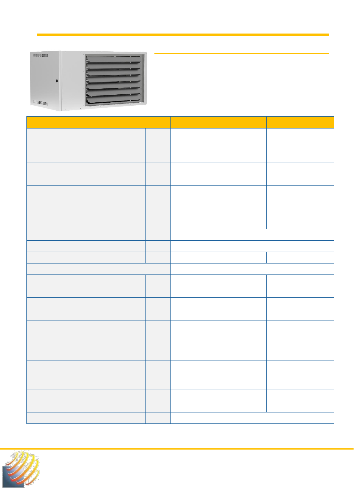
4.1. MH ECO3 Model......................................................................................................................................... 9
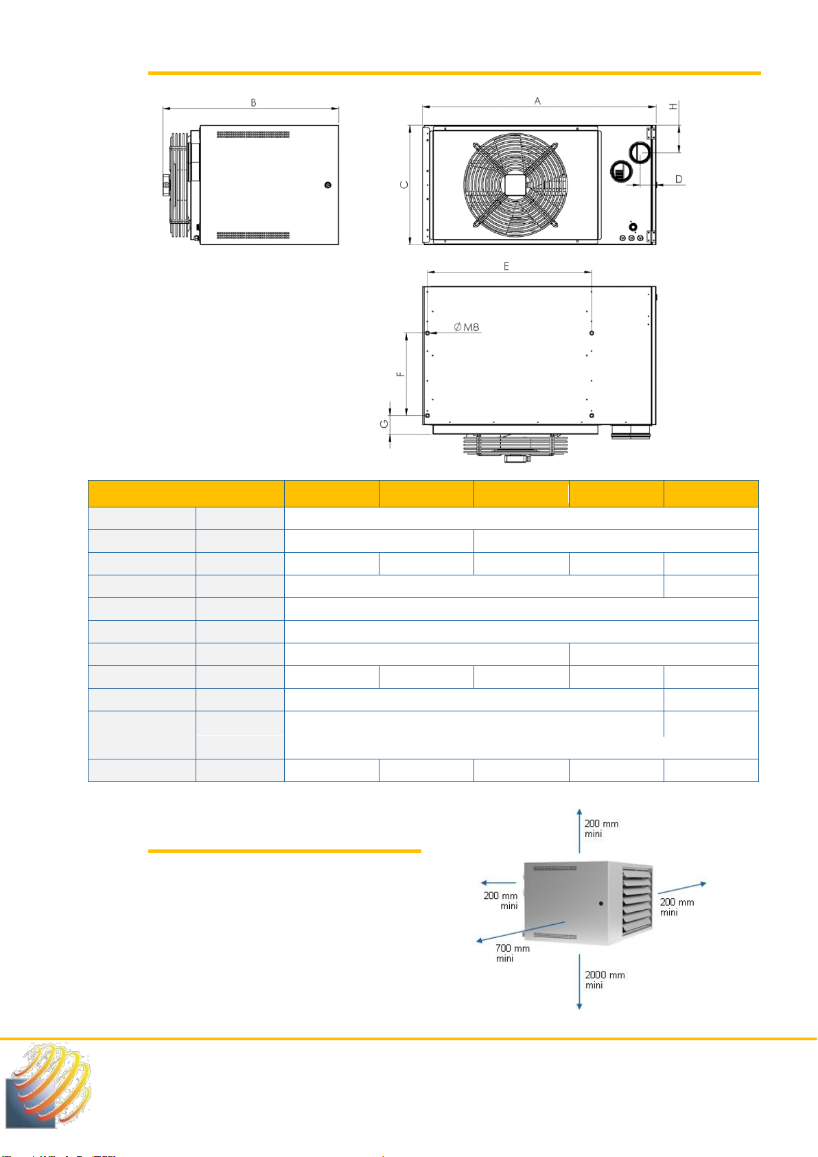
4.1.1. MH ECO3 Dimensions.............................................................................................................................................10
4.1.2. Installation recommendations for MH ECO3.............................................................................................................10
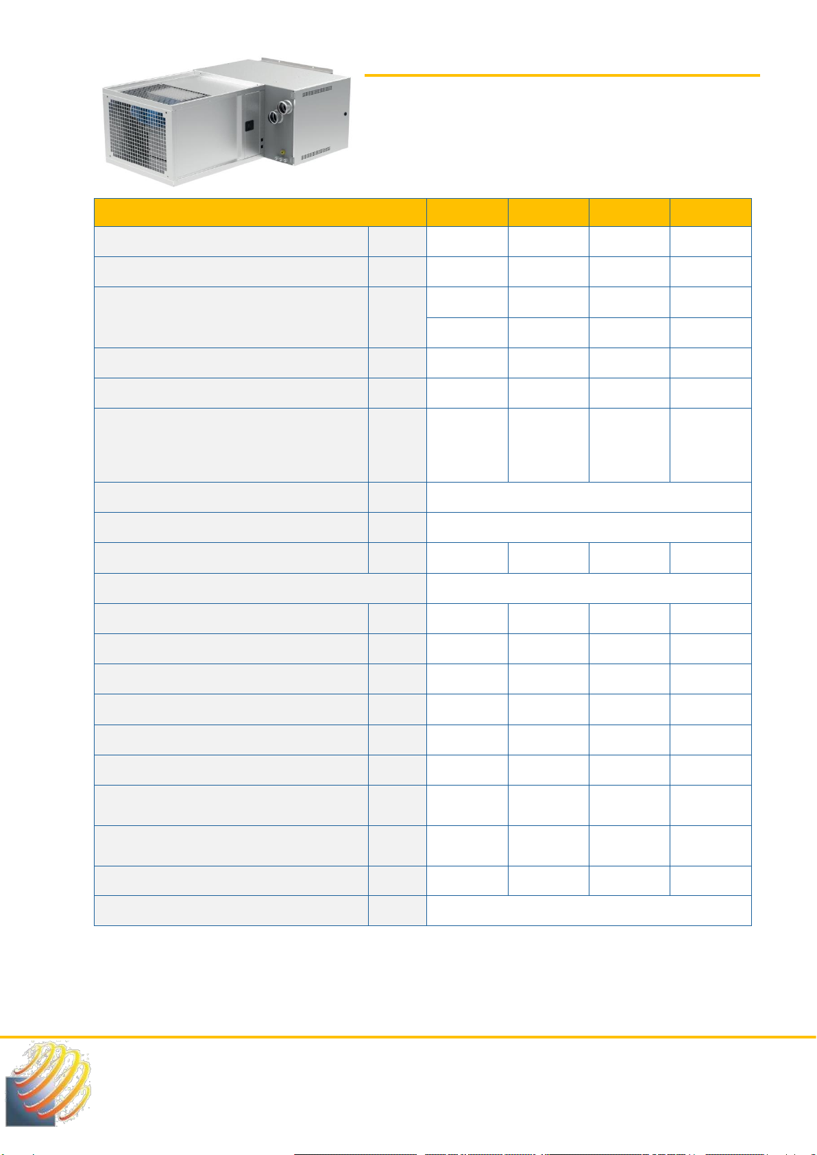
4.2. MV ECO3 Model ........................................................................................................................................11
4.2.1. MV ECO3 Dimensions .............................................................................................................................................12
4.2.2. Installation recommendations for MV ECO3.............................................................................................................12
4.3. MC ECO3 Model........................................................................................................................................13
4.3.1. Pressure / Air flow ratio for MC ECO 3.....................................................................................................................14
4.3.2. MC ECO3 Dimensions.............................................................................................................................................16
4.3.3. Variable Speed Driver..............................................................................................................................................17
5. Fixing the devices ...........................................................................................................19
5.1. Summary of existing supports ................................................................................................................19
5.1.1. Rotating wall bracket................................................................................................................................................19
5.1.2. Fixed wall bracket ....................................................................................................................................................19
5.1.3. Suspension bracket..................................................................................................................................................19
5.2. SMR rotating wall bracket........................................................................................................................20
5.2.1. SMR dimensions......................................................................................................................................................20
5.2.2. SMR furniture...........................................................................................................................................................20
5.3. SMF fixed wall bracket .............................................................................................................................21
5.3.1. SMF dimensions ......................................................................................................................................................21
5.3.2. SMF furniture...........................................................................................................................................................21
5.4. IPN fixing kit..............................................................................................................................................22
5.5. SDS suspension support .........................................................................................................................22
6. Electrical Wiring ..............................................................................................................23
6.1. Internal wiring diagram of ECO 3 heaters...............................................................................................23
6.2. Electrical connection between internal components ............................................................................24
6.3. Pilot wire principle....................................................................................................................................25
6.3.1. Pilot wire principle diagram ......................................................................................................................................25
6.4. Connection of standard controllers........................................................................................................26
6.4.1. TM1 EVO simple Thermostat...................................................................................................................................26
6.4.2. TM2 EVO V2 Touchscreen multi setting thermostat.................................................................................................27
7. Connections flue pipes...................................................................................................28
7.1. General information..................................................................................................................................28
7.2. Summary of existing flue kits..................................................................................................................28

TECHNICAL INSTRUCTIONS –Warm air Heaters ECO3 –NT20005I-GB –07/11/2023
SOLARONICS Chauffage SAS. ZI n°3, 78 rue du Kemmel –CS 20302 –59429 ARMENTIERES CEDEX
Phone : 03.20.10.59.59 - Fax : 03.20.35.57.22
Web site : www.solaronics.com
Page 3 from 54
7.3. B22 kit connection....................................................................................................................................29
7.3.1. Description...............................................................................................................................................................29
7.3.2. Pressure drop calculation.........................................................................................................................................30
7.4. C32 Kit Connection...................................................................................................................................31
7.4.1. Description...............................................................................................................................................................31
7.4.2. Pressure drop calculation.........................................................................................................................................32
7.5. C12 Kit connection ...................................................................................................................................33
7.5.1. Description...............................................................................................................................................................33
7.5.2. Pressure drop calculation.........................................................................................................................................34
8. Gas connection................................................................................................................35
8.1. Air heaters connection.............................................................................................................................35
9. Gas circuit........................................................................................................................36
9.1. Gas change over.......................................................................................................................................36
9.2. Gas manifold adjustment table................................................................................................................37
9.3. Burner combustion adjustment...............................................................................................................37
10. Commissioning and adjustment of the control setpoints ............................................40
10.1. Preliminary check.....................................................................................................................................40
10.2. Use of the control board ..........................................................................................................................41
10.3. Gas heater settings via the control board ..............................................................................................44
11. Maintenance.....................................................................................................................46
12. Spare parts.......................................................................................................................47
12.1. MH and MV ECO 3 Models .......................................................................................................................47
12.2. MC ECO 3 Model.......................................................................................................................................48
13. Troubleshooting..............................................................................................................49
13.1. Failure list and solutions..........................................................................................................................49
13.2. List of general problems ..........................................................................................................................51
14. Warranty...........................................................................................................................52
ANNEX.....................................................................................................................................53
End of life of the equipment.....................................................................................................................................................53
Good safety practice................................................................................................................................................................53
A smell of gas, the right reflexes..............................................................................................................................................53

TECHNICAL INSTRUCTIONS –Warm air Heaters ECO3 –NT20005I-GB –07/11/2023
SOLARONICS Chauffage SAS. ZI n°3, 78 rue du Kemmel –CS 20302 –59429 ARMENTIERES CEDEX
Phone : 03.20.10.59.59 - Fax : 03.20.35.57.22
Web site : www.solaronics.com
Page 4 from 54
1. Introduction
In these instructions, warnings are used to draw attention to particular indications. This is to ensure the safety
of the user, to avoid problems and to guarantee the correct functioning of the appliance.
WARNING
Indicates a possible dangerous situation that may result in personal injury and/or property
damage.
Report important information.
Report a reference to other instructions or pages in the manual.
Before installing and commissioning the appliance, read the instructions carefully.
1.1. General
1.1.1. Manufacturer’s liability
Our products are manufactured in compliance with the requirements of the various applicable European
directives and are therefore delivered with the CE(EC) label and all the necessary documents.
As we are concerned about the quality of our products, we are constantly seeking to improve them. We
therefore reserve the right to modify the characteristics indicated in this document at any time. Our liability as
manufacturer does not apply in the following cases:
•Non-compliance with the instructions for use of the appliance.
•Failure to maintain the appliance properly.
•Failure to follow the installation instructions for the appliance.
1.1.2. Installer’s liability
The installer is responsible for the installation and initial operation of the appliance. The installer must observe
the following instructions:
•Read and follow the instructions in the manuals supplied with the appliance.
•Carry out the installation in accordance with current legislation and standards.
•Carry out the initial commissioning and all necessary checks.
•Explain the installation to the user.
•Inform the user that he/she cannot make any changes to the design of the equipment and
the installation. The slightest modification (exchange, removal...) of safety components or
parts will systematically lead to the withdrawal of the CE(EC) label for the equipment.
•Warn the user of the obligation to check and maintain the equipment.
•Give all manuals to the user.

TECHNICAL INSTRUCTIONS –Warm air Heaters ECO3 –NT20005I-GB –07/11/2023
SOLARONICS Chauffage SAS. ZI n°3, 78 rue du Kemmel –CS 20302 –59429 ARMENTIERES CEDEX
Phone : 03.20.10.59.59 - Fax : 03.20.35.57.22
Web site : www.solaronics.com
Page 5 from 54
1.1.3. User’s liability
In order to ensure optimal operation of the appliance, the user must observe the following instructions:
•Read and follow the instructions in the manuals supplied with the appliance.
•Use qualified professionals to carry out the installation and initial start-up.
•Have the installation explained by the installer.
•Have the necessary checks and maintenance carried out.
•Keep the instructions in good condition near the appliance.
A maintenance contract is strongly recommended and is compulsory for appliances installed in public
buildings.
1.2. Certifications
The equipment complies with the essential requirements of Regulation (EU)2016/426 « Gas appliances ». It is
registered under the number n° 1312DL6489, standards EN17082:2019.
The appliances covered by this annual also comply with the directives:
•Low voltage 2014/35/EU
•Electromagnetic Compatibility 2014/30/EU
•Eco-design 2009/125/CE, according to the requirements of Regulation (EU) 2016/2281-2282-
2283 of 30 November 2016.
2. Safety instructions and recommendations
2.1. Safety instructions
WARNING
The gas heater is a live appliance and as such it must be connected to the installation’s ground.
•It’s forbidden to block and/or reduce the ventilation openings of the installation room or the
appliance.
•Never block the smoke exhaust or the fresh air intake.
•Never make any changes to the settings made by the qualified professional.
•Never spray water on the heater, or touch the heater with wet body parts and/or bare feet.
•Do not place or hang any object on the heater.
•Do not work on the heater until it has been disconnected from the electrical supply and the
gas supply has been cut off.
•Do not change the type of gas used, the appliance settings, the safety or control systems, as
this could lead to dangerous situations.
Contact a qualified technician in the event of the change in gas, gas pressure or supply voltage.
If the appliance is not used for a long period of time, disconnect the power supply. When restarting the
appliance, it is advisable to call in qualified personnel. In general, all repair and maintenance work must be
carried out only by authorized and qualified personnel.

TECHNICAL INSTRUCTIONS –Warm air Heaters ECO3 –NT20005I-GB –07/11/2023
SOLARONICS Chauffage SAS. ZI n°3, 78 rue du Kemmel –CS 20302 –59429 ARMENTIERES CEDEX
Phone : 03.20.10.59.59 - Fax : 03.20.35.57.22
Web site : www.solaronics.com
Page 6 from 54
The subscription of maintenance contract is strongly recommended and is compulsory in the case of
appliances installed in an establishment receiving the public.
2.2. Caution
Electrical components, drive mechanisms and fuel gas can cause injury. To protect against these inherent risks
during installation or maintenance, the electrical supply must be disconnected and the gas supply valve closed.
All persons involved in the installation or servicing of this equipment must comply with all relevant
occupational health and safety standards.
2.3. Recommendations
Gas heaters are intended for heating in industrial and commercial premises.
The greatest care should therefore be taken during installation and adjustment.
We recommend that you entrust their commissioning to Solaronics Chauffage.
Maintenance of the appliances should be carried out every year to ensure their availability, maintain their high
level of performance and also their operational safety.
WARNING
•Only a qualified professional is allowed to work on the unit and the installation.
•This manual is an integral part of the appliance and must always be kept with the appliance, even if it
is transferred to another owner or user.
•Never remove or cover the labels and data plates attached to the appliance. The labels and data plates
must be legible for the entire life of the appliance. The labels and data plates must be legible for the
entire life of the appliance.
•Install the appliance in an adequately ventilated room.
Consult us for any other application than those described in this document.
NOT TO DO !
Do not install air heaters:
•In locals where there is a risk of explosion.
•In locals containing vapours from chlorinated compounds.
•In rooms with a high content of combustible dust.
•In rooms with high humidity (electrical hazard)
•In rooms with domestic use.

TECHNICAL INSTRUCTIONS –Warm air Heaters ECO3 –NT20005I-GB –07/11/2023
SOLARONICS Chauffage SAS. ZI n°3, 78 rue du Kemmel –CS 20302 –59429 ARMENTIERES CEDEX
Phone : 03.20.10.59.59 - Fax : 03.20.35.57.22
Web site : www.solaronics.com
Page 7 from 54
3. Description
The Minigaz Eco3 gas air heater is an independent warm air generator, running on natural gas or propane.
It is a « direct » gas air heating system; it is a heat production and emission device without intermediate heat
transfer fluid.
For the entire range described in this manual, the combustion products are discharged from the room via an
extractor. The combustion air is taken from the room or from the outside.
These appliances can be connected to a vertical or horizontal flue or to a chimney. They operate with the
different gases indicated on their nameplate in accordance with the European directive.
3.1. Main components
3.2. Operation
When there is heating demand, the smoke extractor starts via the room thermostat.
After a few seconds of pre-ventilation, to ensure that there is no gas in the combustion chamber, the burner
is ignited by the ignition electrode. The rise in temperature of the heat exchanger triggers the start-up of the
blowing fan, located at the back of the appliance. The produced hot air then is blown into the room.
While the setpoint temperature is reached, the thermostat gives the stop command and the burner switches
off. The blowing fan continues to blow for about 1 minute until the remaining heat in the heat exchanger has
been removed.
3.3. Safety
The flame failure, during the ignition or during operation, is detected by the ionization sensor and the gas
solenoid valve is immediately closed. This default can be reset remotely or on the appliance.
The thermal protection of the exchanger is ensured by two thermostats.
The first, with automatic reset, protects against insufficient air flow (obstructions, fan failure). The second,
with manual reset, is set at a higher threshold than the first. It protects the appliance from severe overheating
due to operating problems or improper use.
Louvers
Blowing fan
Exhaust fan
Control board
Gas burner

TECHNICAL INSTRUCTIONS –Warm air Heaters ECO3 –NT20005I-GB –07/11/2023
SOLARONICS Chauffage SAS. ZI n°3, 78 rue du Kemmel –CS 20302 –59429 ARMENTIERES CEDEX
Phone : 03.20.10.59.59 - Fax : 03.20.35.57.22
Web site : www.solaronics.com
Page 8 from 54
Make sure that the appliance can be normally supplied with combustion air at atmospheric pressure (any
modification of the building after installation of the appliance must be carried out taking this into account).
Excessive negative pressure in the room can disrupt the proper operation of the appliance by depriving it of
the air necessary for combustion.
3.4. Switching off
To shut down the appliance for a short period of time, simply cut the thermostatic line (set the thermostat to
a minimum setting or turn off the thermostat switch)
For a longer shutdown, cut the thermostatic line, close the gas valve and cut the electrical supply, taking care
to wait for the ventilation to stop.
Gas and electricity should only be cut off in case of emergency or for long periods of time.
IMPORTANT: Never cut off the power supply to the appliance during the operating or cooling cycle of the
exchanger. Failure to follow these instructions may cause premature deterioration of the exchanger and will
result in loss of warranty.
3.5. Control board
These units are equipped with a control board that allows smart operating management. In the event of a
default, the board indicates the source of the problem and facilitates the work of the technician for
troubleshooting.

TECHNICAL INSTRUCTIONS –Warm air Heaters ECO3 –NT20005I-GB –07/11/2023
SOLARONICS Chauffage SAS. ZI n°3, 78 rue du Kemmel –CS 20302 –59429 ARMENTIERES CEDEX
Phone : 03.20.10.59.59 - Fax : 03.20.35.57.22
Web site : www.solaronics.com
Page 9 from 54
4. Technical Characteristics
4.1. MH ECO3 Model
The MINIGAZ MH ECO3 gas heaters are equipped with an axial
fan and a two-stage gas burner.
The MH ECO3 are available in 5 models from 25 to 80 kW and are
designed for horizontal installation and direct blowing.
MODELS
MH25
MH35
MH45
MH60
MH80
Heat input HHV
kW
29.1
40.4
51.4
67.8
88.6
Heat input LCV
kW
26.3
36.4
46.3
61.1
79.8
Nominal output (P rated, h)
kW
24.2
33.5
42.7
56.0
72.9
Minimal power (P min)
kW
13.8
19.1
24.4
32.3
42.1
Efficiency at nominal heat output (ƞnom)
%
92.1
92.2
92.2
91.6
91.4
Efficiency at minimal power (ƞpl)
%
94.8
94.8
95.1
95.2
95.2
Gas flow at 15°C
Natural G20
Groningen G25
Propane G31
m3/h
m3/h
Kg/h
2.50
2.68
2.05
3.47
3.73
2.84
4.41
4.74
3.61
5.82
6.25
4.77
7.60
8.17
6.23
Nox with 0 % O2
mg/kWh
< 69
CO Value
ppm
< 120
Seasonal energy efficiency (ƞs,h)
%
78.7
78.1
78.5
78.6
78.5
Supply voltage
Single phase 230 V 50 Hz
Amperage
A
1.05
1.75
2
3.25
3.95
Maximum electrical power with fan
W
230
380
430
700
850
Consumption at P Maxi with fan
W
18
32
47
58
77
Consumption at P Mini without fan
W
10
18
22
24
30
Standby consumption
W
3
3
3
3
3
Air flow at 15 °C
m3/h
3 580
4 250
5 800
7 700
10 000
Air temperature increase at maximum power P
Maxi
°C
19.9
23.2
21.6
21.4
21.5
Air temperature increase at minimum power P
Mini
°C
11.3
13.2
12.4
12.3
12.4
Acoustic power –Lw (+/- 4 dB)
dB(A)
71.2
79.5
77.5
86.7
83.4
Acoustic pressure at 5 m –Lp (+/- 4 dB)
dB(A)
49.2
57.5
55.5
64.7
61.4
Available pressure loss air/fumes
Pa
120
200
250
300
240
Maximum condensation produced
l/h
No condensate

TECHNICAL INSTRUCTIONS –Warm air Heaters ECO3 –NT20005I-GB –07/11/2023
SOLARONICS Chauffage SAS. ZI n°3, 78 rue du Kemmel –CS 20302 –59429 ARMENTIERES CEDEX
Phone : 03.20.10.59.59 - Fax : 03.20.35.57.22
Web site : www.solaronics.com
Page 10 from 54
4.1.1. MH ECO3 Dimensions
TYPES
MH 25
MH 35
MH 45
MH 60
MH 80
A
mm
1 060
B
mm
800
875
C
mm
495
545
600
710
912
D
mm
72
82
E
mm
746
F
mm
250
G
mm
170
249
H
mm
100
125
153
208
273
Ø flue gas
mm
80
100
Ø Air
mm
80
100
Ø Gas
‘’
3/4
Weight
kg
82
95
108
132
152
4.1.2. Installation recommendations
for MH ECO3
Top view
Lateral view
Back view

TECHNICAL INSTRUCTIONS –Warm air Heaters ECO3 –NT20005I-GB –07/11/2023
SOLARONICS Chauffage SAS. ZI n°3, 78 rue du Kemmel –CS 20302 –59429 ARMENTIERES CEDEX
Phone : 03.20.10.59.59 - Fax : 03.20.35.57.22
Web site : www.solaronics.com
Page 11 from 54
4.2. MV ECO3 Model
The MINIGAZ MV ECO3 gas heaters are equipped with an axial fan
and a two-stage gas burner.
The MV ECO3 are available in 4 models from 35 to 80 kW and
designed for vertical installation and direct blowing.
TYPES
MV35
MV45
MV60
MV80
Heat input HHV
kW
40.4
51.4
67.8
88.6
Heat input LCV
kW
36.4
46.3
61.1
79.8
Nominal output (P rated, h)
kW
33.5
42.7
56.0
72.9
Minimal power (P min)
kW
19.1
24.4
32.3
42.1
Efficiency at nominal heat output (ƞnom)
%
92.2
92.2
91.6
91.4
Efficiency at minimal power (ƞpl)
%
94.8
95.1
95.2
95.2
Gas flow at 15°C
Natural G20
Groningen G25
Propane G31
m3/h
m3/h
Kg/h
3.47
3.73
2.84
4.41
4.74
3.61
5.82
6.25
4.77
7.60
8.17
6.23
Nox with 0 % O2
mg/kWh
< 69
CO Value
ppm
< 120
Seasonal energy efficiency (ƞs,h)
%
78.1
78.5
78.6
78.5
Supply voltage
Single phase 230 V 50 Hz
Amperage
A
1.75
2
3.25
3.95
Maximum electrical power with fan
W
380
430
700
850
Consumption at P Maxi with fan
W
32
47
58
77
Consumption at P Mini without fan
W
18
22
24
30
Standby consumption
W
3
3
3
3
Air flow at 15 °C
m3/h
4 250
5 800
7 700
10 000
Air temperature increase at maximum power P
Maxi
°C
23.2
21.6
21.4
21.5
Air temperature increase at minimum power P
Mini
°C
13.2
12.4
12.3
12.4
Available pressure loss air/fumes
Pa
200
250
300
240
Maximum condensation produced
l/h
No condensate

TECHNICAL INSTRUCTIONS –Warm air Heaters ECO3 –NT20005I-GB –07/11/2023
SOLARONICS Chauffage SAS. ZI n°3, 78 rue du Kemmel –CS 20302 –59429 ARMENTIERES CEDEX
Phone : 03.20.10.59.59 - Fax : 03.20.35.57.22
Web site : www.solaronics.com
Page 12 from 54
4.2.1. MV ECO3 Dimensions
TYPES
MV 35
MV 45
MV 60
MV 80
A
mm
1 060
B
mm
800
875
C
mm
545
600
710
912
D
mm
72
82
E
mm
746
F
mm
250
G
mm
170
249
H
mm
125
153
208
273
Ø Flue gas
mm
80
100
Ø Air
mm
80
100
Ø Gas
‘’
3/4
Weight
kg
95
108
132
152
4.2.2. Installation recommendations for MV
ECO3
Models
MV35
MV45
MV60
MV80
Height Mini
4m
5 m
6 m
Height Maxi
6m
8 m
10 m
Lateral view
Back view
Top view

TECHNICAL INSTRUCTIONS –Warm air Heaters ECO3 –NT20005I-GB –07/11/2023
SOLARONICS Chauffage SAS. ZI n°3, 78 rue du Kemmel –CS 20302 –59429 ARMENTIERES CEDEX
Phone : 03.20.10.59.59 - Fax : 03.20.35.57.22
Web site : www.solaronics.com
Page 13 from 54
4.3. MC ECO3 Model
The MINIGAZ MC ECO3 gas heaters are equipped with a
centrifugal fan and a two-stage gas burner.
The MC ECO3 are available in 4 models from 35 to 80 kW and
are designed for horizontal installation and ducting.
MODELS
MC35
MC45
MC60
MC80
Heat input HHV
kW
40.4
51.4
67.8
88.6
Heat input LCV
kW
36.4
46.3
61.1
79.8
Nominal output (P rated, h)
kW
33.5
42.7
56.0
72.9
Minimal power (P min)
kW
19.1
24.4
32.3
42.1
Efficiency at nominal heat output (ƞnom)
%
92.2
92.2
91.6
91.4
Efficiency at minimal power (ƞpl)
%
94.8
95.1
95.2
95.2
Gas flow at 15°C
Natural G20
Groningen G25
Propane G31
m3/h
m3/h
Kg/h
3.47
3.73
2.84
4.41
4.74
3.61
5.82
6.25
4.77
7.60
8.17
6.23
Nox with 0 % O2
mg/kWh
< 69
CO Value
ppm
< 120
Seasonal energy efficiency (ƞs,h)
%
78.1
78.5
78.6
78.5
Supply voltage
Single phased 230 V 50 Hz
Amperage
A
1.75
2
3.25
3.95
Maximum electrical power with fan
W
380
430
700
850
Consumption at P Maxi with fan
W
32
47
58
77
Consumption at P Mini without fan
W
18
22
24
30
Standby consumption
W
3
3
3
3
Air flow at 15 °C
m3/h
4 250
5 250
7 000
9 000
Air temperature increase at maximum power P
Maxi
°C
23.2
23.9
23.5
23.9
Air temperature increase at minimum power P
Mini
°C
13.2
13.7
13.6
13.8
Available pressure loss air/fumes
Pa
200
250
300
240
Maximum condensation produced
l/h
No condensate

TECHNICAL INSTRUCTIONS –Warm air Heaters ECO3 –NT20005I-GB –07/11/2023
SOLARONICS Chauffage SAS. ZI n°3, 78 rue du Kemmel –CS 20302 –59429 ARMENTIERES CEDEX
Phone : 03.20.10.59.59 - Fax : 03.20.35.57.22
Web site : www.solaronics.com
Page 14 from 54
4.3.1. Pressure / Air flow ratio for MC ECO 3
4.3.1.1. MC 35 ECO 3
It is equipped with a double inlet centrifugal fan and a belt drive with a 90/118 gear ratio on a 750 W three-
phase motor. (Rotation 1140 rpm)
The motor is connected to 230 V single phase input and 230 V three phase output frequency converter.
The frequency converter protects and regulates the speed of the motor to obtain the desired performance.
Airflow
(m3/h)
Available
pressure
(Pa)
Delta T
(°C)
Motor
power
(W)
dBa
(LwoA)
4 500
190
22
770
82.0
4 250
211
23
720
80.9
4 000
226
25
670
80.0
3 750
241
26
600
79.0
3 500
250
28
540
78.2
3 250
259
30
485
77.5
3 000
267
33
475
76.8
2 750
270
36
400
75.8
2 500
271
39
350
75.0
2 250
275
44
300
74.4
4.3.1.2. MC 45 ECO 3
It is equipped with a double inlet centrifugal fan and a belt drive with a of 112/140 gear ratio on a 1 500 W
three-phase motor.( Rotation 1140rpm)
The motor is connected to a 230V single phase input and 230V three phase output frequency converter
The frequency converter protects and regulates the speed of the motor to obtain the desired performance.
Airflow
(m3/h)
Available
pressure
(Pa)
Delta T
(°C)
Motor
power
(W)
dBa
(LwoA)
6 000
180
21
1 400
87.0
5 750
208
22
1 330
86.4
5 500
226
23
1 250
85.8
5 250
253
24
1 200
84.8
5 000
273
25
1 050
84.1
4 750
289
26
980
83.3
4 500
304
28
880
82.2
4 250
312
30
820
81.4
4 000
326
31
780
80.4
3 750
332
33
700
79.4

TECHNICAL INSTRUCTIONS –Warm air Heaters ECO3 –NT20005I-GB –07/11/2023
SOLARONICS Chauffage SAS. ZI n°3, 78 rue du Kemmel –CS 20302 –59429 ARMENTIERES CEDEX
Phone : 03.20.10.59.59 - Fax : 03.20.35.57.22
Web site : www.solaronics.com
Page 15 from 54
4.3.1.3. MC 60 ECO 3
It is equipped with a double inlet centrifugal fan and a belt drive with a 112/170 gear ratio on a 1 500 W three-
phase motor. (Rotation 940 rpm)
The motor is connected to a 230 V single phase input and 230V three phase output frequency converter.
The frequency converter protects and regulates the speed of the motor in order to obtain the desired
performance.
Above a flow rate of 7 250 m3/h, consider the high flow rate option with three-phase frequency converter
which requires a three-phase + neutral supply to the unit.
Airflow
(m3/h)
Available
pressure
(Pa)
Delta T
(°C)
Motor
power
(W)
dBa
(LwoA)
8 000
175
21
1 800
87.0
7 750
206
21
1 700
86.7
7 500
222
22
1 600
85.8
7 250
238
23
1 500
85.0
7 000
253
24
1 420
84.7
6 750
264
24
1 340
84.0
6 500
274
25
1 275
83.5
6 250
284
26
1 220
82.7
6 000
294
27
1 140
82.1
5 750
298
29
1 070
81.6
4.3.1.4. MC 80 ECO 3
It is equipped with a double inlet centrifugal fan with a belt drive with a 118/224 gear ratio in a 2200W three-
phase motor. (Rotation 745 rpm)
The motor is connected to a single 230V input and three 230V output frequency converter.
The frequency converter protects and regulates the speed of the motor in order to obtain the desired
performance.
Airflow
(m3/h)
Available
pressure
(Pa)
Delta T
(°C)
Motor
power
(W)
dBa
(LwoA)
10 500
180
20
2 150
88.0
10 000
209
21
1 950
86.9
9 500
228
23
1 800
86.0
9 000
247
24
1 650
85.0
8 500
264
25
1 500
83.8
8 000
277
27
1 400
82.9
7 500
289
29
1 280
81.7
7 000
296
31
1 150
80.8
6 500
302
33
1 050
79.8
6 000
307
36
900
79.0

TECHNICAL INSTRUCTIONS –Warm air Heaters ECO3 –NT20005I-GB –07/11/2023
SOLARONICS Chauffage SAS. ZI n°3, 78 rue du Kemmel –CS 20302 –59429 ARMENTIERES CEDEX
Phone : 03.20.10.59.59 - Fax : 03.20.35.57.22
Web site : www.solaronics.com
Page 16 from 54
4.3.2. MC ECO3 Dimensions
Models
MC 35
MC 45
MC 60
MC 80
A
mm
1 060
B
mm
1 460
1 530
1 560
C
mm
545
600
710
912
D
mm
787
F
mm
100
95
G
mm
205
G1
mm
700
G2
mm
485
540
650
853
R
mm
130
R1
mm
630
R2
mm
430
530
Ø Flue gas
mm
80
100
Ø Air
mm
80
100
Ø Gas
‘’
3/4
Weight
kg
145
200

TECHNICAL INSTRUCTIONS –Warm air Heaters ECO3 –NT20005I-GB –07/11/2023
SOLARONICS Chauffage SAS. ZI n°3, 78 rue du Kemmel –CS 20302 –59429 ARMENTIERES CEDEX
Phone : 03.20.10.59.59 - Fax : 03.20.35.57.22
Web site : www.solaronics.com
Page 17 from 54
4.3.3. Variable Speed Driver
MINIGAZ MC ECO3 range warm air heaters are fitted as standard with a variable speed driver. This protects
the motor and adapts its rotation frequency to the pressure drop in the supply network. The differential
pressure sensor monitors the ΔP in the fan box, enabling instant adaptation of the variable speed driver for
greater airflow stability.
Group
Subgroup
Description
Examples of fonctions
P00
P0.00 –P00.18
Basic parameters
Execute order type, maximum frequency,
ramp time
P01
P1.00 –P01.25
Order start / stop
DC injection braking, coast to stop, delayed
start, automatic restart
P02
P02.00 –P02-26
Parameters of motor 1
Motor parameters, kW, current, speed
P09
P09.00 –P09-16
PID control parameters
PID, SV and encoder input parameters
P11
P11.00 –P11-16
Protection parameters
Execute protection function trip/exit levels
Factory settings
The drive is factory-set to deliver the nominal air flow rate specified in the technical data.
WARNING
The units are set up for optimum performance, but changing the factory settings may cause malfunctions or
even damage to the unit. For example, increasing the air flow rate by +15% of the nominal air flow can lead to
condensation in the heat exchanger, and ultimately to premature deterioration.gas heater is a live appliance
and as such it must be connected to the installation’s ground.
Variable speed driver
Circuit breaker of
variable speed driver
Relay for variable
speed driver
operating order
Differential pressure sensor

TECHNICAL INSTRUCTIONS –Warm air Heaters ECO3 –NT20005I-GB –07/11/2023
SOLARONICS Chauffage SAS. ZI n°3, 78 rue du Kemmel –CS 20302 –59429 ARMENTIERES CEDEX
Phone : 03.20.10.59.59 - Fax : 03.20.35.57.22
Web site : www.solaronics.com
Page 18 from 54
Code
Function
MC 35
MC 45
MC 60
MC 80
Basic parameters
P00.01
Execution command channel
1
1
1
1
P00.06
Frequency control selection
7
7
7
7
P00.11
Acceleration time (s)
60
60
60
60
P00.12
Deceleration time (s)
60
60
60
60
Order start / stop
P01.01
Starting frequency (Hz)
30
30
30
30
P01.18
Protection of powered terminal execution
1
1
1
1
Motor parameters
P02.01
Motor rated power (kW)
0,7
1,5
1,5
2,2
P02.02
Motor rated frequency (Hz)
50
50
50
50
P02.03
Motor rated speed (rpm)
1 445
1445
1 445
1 445
P02.04
Motor rated voltage (V)
220
220
220
220
P02.05
Motor rated current (A)
2,8
5,6
5,6
8,2
PID control parameters
P09.00
PID reference source
0
0
0
0
P09.01
Keyboard PID preset P17.20 = 0.50
32
36
34
20
Keyboard PID preset P17.20 = 0.40
31
35
33
19
P09.02
PID retroactive source
1
1
1
1
P09.03
PID output function
0
0
0
0
P09.04
Proportional gain (%)
30
30
30
30
P09.05
Integral time (s)
5
5
5
5
P09.06
Differential time(s)
0
0
0
0
P09.07
Sampling cycle (s)
0,1
0,1
0,1
0,1
P09.08
PID control deviation limit (%)
0,6
0,6
0,6
0,6
P09.09
PID upper output limit (%)
100
100
100
100
P09.10
PID lower output limit (%)
60
60
60
60
P09.11
Off-circuit feedback detection value (%)
0
0
0
0
P09.12
Off-circuit feedback detection time (s)
0
0
0
0
Protection parameters
P11.06
Current limit level (%)
69
74
74
82

TECHNICAL INSTRUCTIONS –Warm air Heaters ECO3 –NT20005I-GB –07/11/2023
SOLARONICS Chauffage SAS. ZI n°3, 78 rue du Kemmel –CS 20302 –59429 ARMENTIERES CEDEX
Phone : 03.20.10.59.59 - Fax : 03.20.35.57.22
Web site : www.solaronics.com
Page 19 from 54
5. Fixing the devices
The appliances can be fixed to the wall or to the buildings frame. Before fixing the devices, the strength of the
support must be ensured. It is possible to make your own fixing but a preliminary study must be carried out to
ensure the strength of the structures.
For the use of our brackets, always refer to the instructions supplied with the brackets.
5.1. Summary of existing supports
5.1.1. Rotating wall bracket
5.1.2. Fixed wall bracket
5.1.3. Suspension bracket
For MH helicoidal
25 ECO3
35 ECO3
45 ECO3
60 ECO3
80 ECO3
SMR Rotating wall bracket
3500341
Not
compatible
SMR IPN fixing kit
3500047
For MH helicoidal
25 ECO3
35 ECO3
45 ECO3
60 ECO3
80 ECO3
SMF Fixed wall bracket
3500340
SMF IPN fixing kit
3500074
For MV helicoidal
35 ECO3
45 ECO3
60 ECO3
80 ECO3
SDS Suspension bracket
3500343
3500344

TECHNICAL INSTRUCTIONS –Warm air Heaters ECO3 –NT20005I-GB –07/11/2023
SOLARONICS Chauffage SAS. ZI n°3, 78 rue du Kemmel –CS 20302 –59429 ARMENTIERES CEDEX
Phone : 03.20.10.59.59 - Fax : 03.20.35.57.22
Web site : www.solaronics.com
Page 20 from 54
5.2. SMR rotating wall bracket
The « SMR rotating wall bracket » kit (code 3500341) is a rotating wall
bracket for MH 25 ECO3 to MH 60 ECO3 gas heaters.
It can be combined with the SMR IPN Fixing Kit (code 3500047) for fixing
to a metal frame.
The MH 80 Eco3 model is not compatible with the SMR Kit.
5.2.1. SMR dimensions
5.2.2. SMR furniture
8 x Screws M12x30
8 x Nuts M12
16 x Flat washers
M12
8 x Star washers
M12
8 x Flat washers M8
8 x Star washers M12
8 x Screws M8x30
This manual suits for next models
13
Table of contents
Other Solaronics Heater manuals