Solarsol SSP27 User manual

User Manual
Photovoltaic Modules
SSP27

User Manual
Contents
Module Size ................................................................................................................................................................4
Safety instructions......................................................................................................................................................5
Installation guidelines.................................................................................................................................................7
Mechanical installation. .............................................................................................................................................8
Electrical installation. .............................................................................................................................................. 10
Grounding................................................................................................................................................................ 12
Maintenance and care............................................................................................................................................. 15
Transport and storage. ............................................................................................................................................ 15

General information
Thank you for buying SOLARSOL!
Please read the following instructions carefully before transporting, installing or operating SOLARSOL photovoltaic
modules.
This manual contains important information concerning the safety, care and maintenance of SOLARSOL
photovoltaic modules.
The installation and operation of photovoltaic modules requires a high degree of skills and experience, so it must
be performed ONLY BY PROFESSIONALS.
Each module has three labels that identifies the serial number of the product. The label located on the back of the
solar module contains important information about the: Maximum Power, Electric Tolerance, Open Circuit
Voltage (Voc), Short Circuit Current (Isc), Maximum Power Current (Imp) and Maximum Power Voltage (Vmp) , all
of them measured under STC conditions (25 ° C, 1000 W/m2, 1.5 ATM).
SOLARSOL photovoltaic modules have the following dimensions: 1640 mm tall, 990 mm wide and a thickness of
40 mm (See figure 1). Each module has a junction box located at the back of the module with 900 mm long wires
with MC4 connectors. The aluminum frame that protects the module, has eight holes, six of them for the mounted
and the others two must be use only to ground the module.


Safety instructions.
IMPORTANT
Before installing, wiring or handling the photovoltaic modules, please read the
instructions below.
The wrong installation of photovoltaic devices can result in serious injuries.
All installation work must obey the standards established by international, national and local regulations.
Before installation, remove all metallic object and jewelry.
Safety equipment must be worn at all time during the installation.
For your safety use insulated tools and gloves.
Do not allow unauthorized people access to the installation area.
Photovoltaic systems can be installed on roofs or high ground, however, modules should be installed only on
surfaces capable of supporting the additional weight of the panels.
The modules must be anchored to the ceilings by a formal structure result of a complete load analysis.
Do not install photovoltaic modules near flammable substances, gases or vapors.
The fire rating of this module is valid only when mounted in the manner specified in the
mechanical mounting instructions.
Work EXCLUSIVELY in dry conditions. For your safety, do not install or manipulate the
photovoltaic modules under adverse weather conditions.
Reflection caused by snow or water can increase sunlight, raising the power
generated by the solar modules. Additionally, low temperatures can boost the panel power.

Photovoltaic modules produce electricity when exposed to light, which can lead to electric
shocks or burns. They must always be handled with extreme caution.
Even in low light conditions the photovoltaic modules are able to generate a voltage equal
to VOC in STC, do not concentrated artificially sunlight on the module or panel.
Do not install or use broken modules. Contact with the surface of the modules can cause electric shock if the front
glass is broken or the backsheet perforated.
A module with exposed conductivity parts is considered with the requirements of UL 1703 only when it is
electrically grounded in accordance with the instructions presented below and the requirements of the National
Electrical Code.
Modules and module frames must not be drilled, nailed or welded under any circumstances.
Do not disassemble the module or remove any of its parts. The photovoltaic modules do not contain any repairable
parts.
Any module without a frame shall not be considered to comply with the requirements of UL 1703 unless the
module is mounted with hardware that has been tested and evaluated with the module under this standard or by
a field inspection certifying that the installed module complies with the requirements of UL 1703.
Do not connect or disconnect modules when the modules current or an external source is present.

Installation guidelines.
PHOTOVOLTAIC MODULES MUST BE INSTALLED ONLY BY PROFESSIONALS.
The modules must be mounted on resistant structures. The structures must be resistant to corrosion. Before
proceeding with the installation, SOALRSOL recommends to perform a structural stability analysis of the surface
where the modules will be mounted.
The installation structures can be located on roofs or even on the ground.
Install the photovoltaic modules avoiding shadow conditions produced by nearby bodies, such as trees, water
tanks or antennas. Constant shadow conditions reduce the performance of the modules and affect their life time.
Do not install the modules near fountains or pools to avid constantly exposure to water.
Position the front of the solar modules so that it faces the terrestrial equator.
Select the correct inclination angle according to local conditions.

Mechanical installation.
The module is considered to be in compliance with UL 1703 only when the module is mounted in the manner
specified by the mounting instructions below.
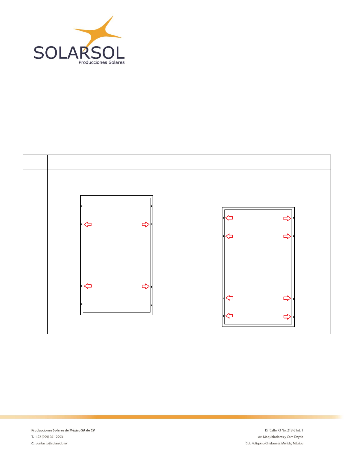
SOLARSOL photovoltaic modules can be installed using the holes found in the aluminum frame (See Figure 2).
They can also be installed using a clamp system.
For any installation method, the photovoltaic modules must be insured in at least 4 different points.
Figure 2. Encircled in red, the installation holes in the module’s frame.
Modules can be installed in landscape or portrait orientation.
The Fire Class Rating of the module in a mounting system in combination with roof covering complete with the
requirements to archive a class C.
To maintain the Fire Class Rating C, the system should have a minimum 10 cm gap between the module frame
and the mounting surface and it must be installed ONLY on surfaces resistant to fire.
SOLARSOL recommends the following installation method for photovoltaic modules:
To do so, it’s necessary a M4 or #10 SS Screw, M4 SS Flat washer, M4 SS Cup washer, M4 SS Toothed washer, M4
SS Nut. Insert the flat washer into the screw and then insert the cup washer before you place it in the mounting
holes. Secure the screw to the aluminum frame using the toothed washer and a backing nut on the end of the
screw.
Normal level of load condition
High level of load condition
Screw fastening to assembly holes
Applies to most of the environmental conditions.
Use four mounting holes.
Applies to harsher environmental conditions such as
storms
Use eight mounting holes.
SOLARSOL DOES NOT INSTALL PHOTOVOLTAIC MODULES. However, you can contact us and we will gladly
communicate you with one of our installers. For further information, email us to: [email protected].
Electrical installation.
Voltage
Current
Power
Open circuit Voltage
38.16 V
Short Circuit Current
8.86 A
Maximum
Power
270 W
Operating Voltage
32.34 V
Current at rated Operating
Voltage
8.36 A
Maximum System voltage
600 V
The electrical characteristics are within ±3 percent of the indicated values of ISC, VOC and Pmax under standard
test conditions (irradiance of 1000 W/m2, AM 1.5 spectrum and a cell temperature of 25°C (77°F)).
Do not install broken modules. Make sure that Jboxes and wires are clean and dry.
SOLARSOL photovoltaic modules are equipped with junction boxes JMTH model JM13 designed to be easily
interconnected in series for their well-connected cable and the connector with IP67. Three By-pass diodes are
located at the interior of the Jbox for overcurrent protection. Each module has two single conductor wires pre-
wired inside the junction box. In addition, the connector conductor wires are equipped with special MC4
connectors for photovoltaic equipment.
The connector plugs are labeled with their respective polarity (red positive and black negative). Check the polarity
when interconnecting the modules and the inverter. A wrong polarity connection can permanently damage all
electronic components of the system.
SOALRSOL recommends USE ONLY dedicated solar cable (6-12 AWG), with temperature resistance between -40°C
to 90°C.
Protect the wires by securing them with clips or tapes to the frames. Avoid squash them or put them under
pressure.
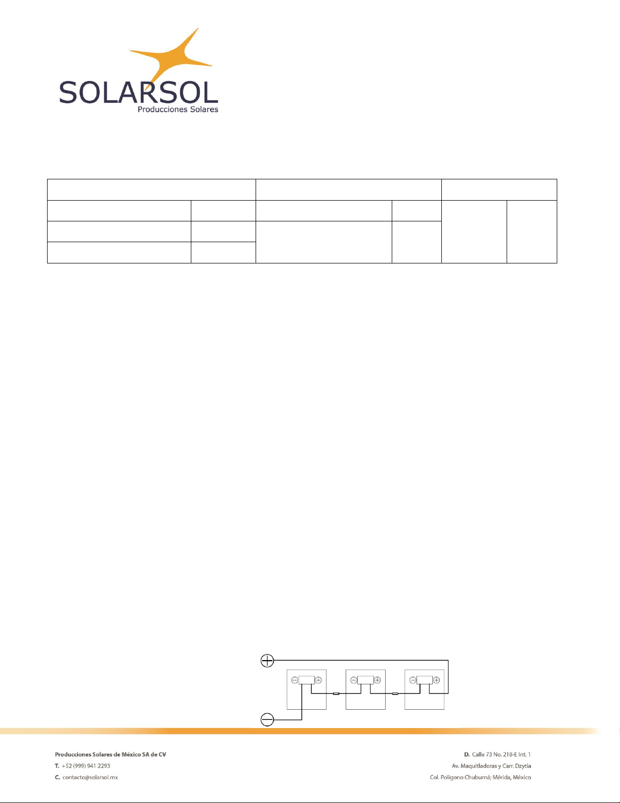
The following diagram shows 3 different ways of interconnect the solar modules.
Series wiring
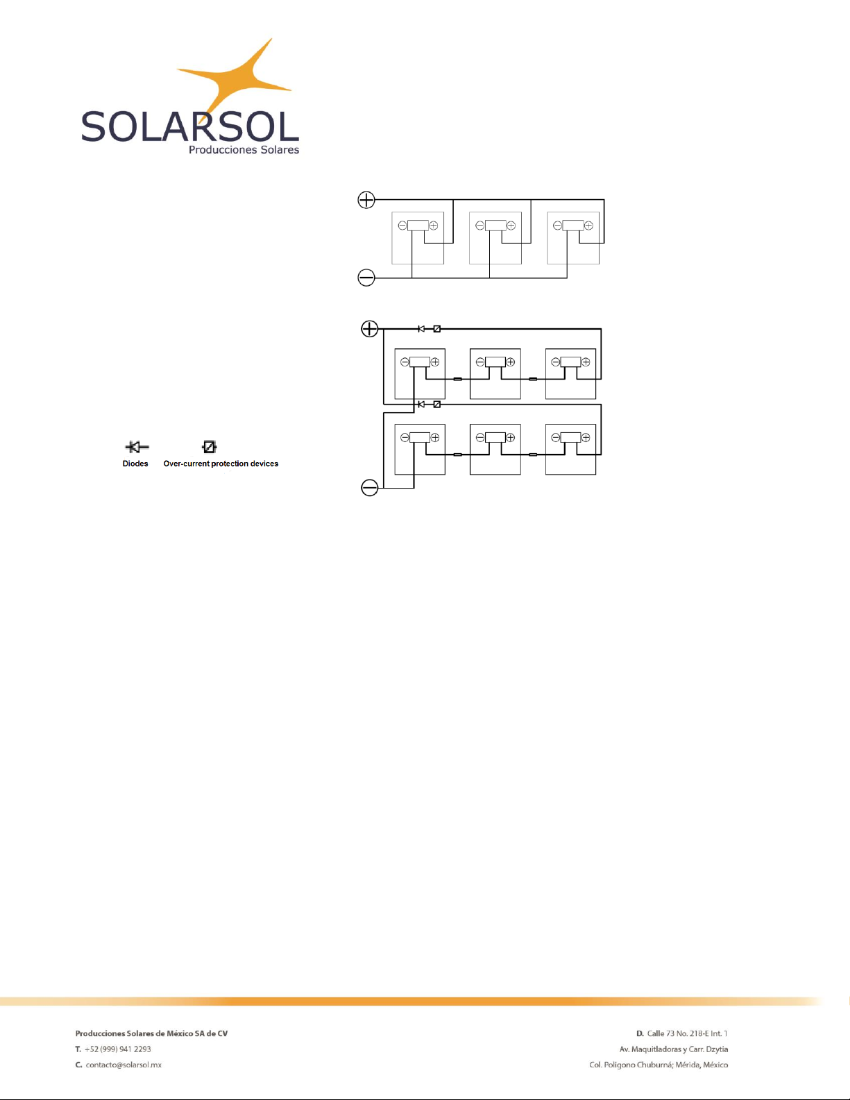
Parallel wiring
Series wiring and Parallel wiring
Interconnect only photovoltaic modules of the same type and power.
Voltages are additive when modules are connected directly in series, and modules currents are additive when
modules are connected directly in parallel.
Make sure that the maximum system voltage is not surpassed when the modules are connected in series. Take
into account the effects of temperature variation on the power and voltage of the modules.
Else, if you connect the modules in parallel, make sure that each line contains the same number of photovoltaic
modules.
Under normal conditions, a photovoltaic module is likely to experience conditions that produce more current
and/or voltage that reported at the standard test conditions. The requirements of the National Electrical Code
(NEC) in article 690 shall be followed to address these increased outputs. In installations not under the
requirements of the NEC, the values of ISC and VOC marked on this module should be multiplied by a factor of
1.25 when determining component voltage ratings, conductor ampacities, overcurrent device rating and size of
controls connected to the PV output.

Grounding.
Every accessible metal part from the photovoltaic system during normal use (the PV module frame,
the structure, the junction boxes and the metal enclosures) regardless of their electrical voltage, must
bond continuously to an equipment-grounding conductor (EGC) to avoid electric hazards.
Any PV source with two terminals (positive and negative) must have a physical grounding conductor.
The Photovoltaic system must have a resistance value of less than 0.1 Ohm when measured between the
grounding terminal and any accessible conductive part. The grounding system may be composed of one or more
grounding electrodes and grounding conductors.
The PV module has two ground pre-drilled holes with 4 mm diameter; they are identified by the symbol and
engraved at the center of both sides of the frame as seen on the following sketch:
Grounding
Holes
Ø 4
mm
Please follow the next considerations to keep optimal mechanical performance:
A. The grounding holes must not be used for the mounting the PV module in any case.
B. Both holes must be sufficient to ground each PV module. Do not drill additional holes to prevent corrosion.
The equipment grounding conductor (EGC) should comply the following conditions:
1. The installation technician or professional must provide all grounding hardware.
2. A green or green-with-yellow-stripes colored insulation should identify all grounding conductors
when insulated.
3. SOLARSOL recommends that the EGC wire gauge must meet the maximum of 6 AWG and the
minimum of 12 AWG.

4. The metal frame of each module from the photovoltaic array must me grounded by a continuous
conductor with no splices.
5. Copper wire must never come in direct contact with the aluminum PV frame to avoid galvanic
corrosion.
6. SOLARSOL always recommends the use of connectors made of stainless steel material to avoid
corrosion. A galvanic corrosion resistant coating must protect all non-stainless- steel connectors
between the module frame and the EGC.
7. The EGC must reach the enclosure where the DC disconnect and the general ground bus are located.
8. If the PV output circuit has a grounding conductor, the grounding connection must be located only on
the local ground bus; then the ground bus must connect to the grounding electrode. It is convenient
that the grounding bus and the PV circuit DC disconnect are in the same enclosure.
9. The junction point between the grounding connector bus and the grounding electrode must be weld
with exothermic or high-temperature welding. Do not use pressure screws for this type of connection.
All grounding measures must comply with the local electrical codes and regulations depending on the geographical
location of the PV modules installation.
Grounding methods suggested by SOLARSOL:
Please note that all the methods should remove the anodizing surface of the grounding holes and/or the aluminum
frame surface. Failure in doing this may cause a poor or none grounding connection.
Option 1: Screw Grounding
Required material and composition structure:
M4 or #10 SS Screw
M4 SS Flat washer
Grounding conductor
M4 SS Cup washer
M4 SS Toothed washer
M4 SS Nut
Instructions:
1. Insert the flat washer into the screw and then insert the cup washer before you place it in the grounding
holes.
2. Secure the screw to the aluminum frame using the toothed washer and a backing nut on the end of the
screw as you place the grounding conductor.
3. Make a small loop with the grounding conductor and place it between the flat washer and the cup washer.
Make sure that the copper does not come in contact with anything but the stainless steel to avoid
corrosion.
4. Use the backing nut to tighten the screw in place with a 4Nm torque and make sure that the toothed
washer anchors the frame.
Option 2: Bolt & nut Grounding
Required material and composition structure:
M4 SS cap bolt
M4 SS Flat washer
Grounding conductor
M4 SS Cup washer
M4 SS Toothed washer
Instructions:
1. Place the cup washer with the concave side up between the frame and the wire.
2. Fix the wire between the flat washer and the cup washer
3. Insert the cap bolt to unify the washers with the frame.
4. Using the toothed nut tighten the bolt with the help of a wrench. Use a 1.5Nm torque to tighten the
bolt.
IMPORTANT! A professional must ground the system; failure to comply with this requirement could result in
serious damage, will reduce system performance and invalidate SOLARSOL’s Warranty for PV Modules.
Maintenance and care.
To maximize the modules life and performance, SOLARSOL suggest follow the next recommendations:
-Periodically clean the modules surface with a wet cotton rag to avoid accumulation of snow, dust, leaves
and pollen that could reduce the efficiency of the panel.
-Do not lift the modules through the junction box or cables.
-Do not step, stand or sit on the modules.
-Keep the junction box closed at all times.
-Regularly inspect the photovoltaic modules.
If you find any of the following defects, SOLARSOL recommends you to contact your installer:
Crack son the glass Surface.
Burns on the cells or the back sheet.
Transport and storage.
The photovoltaic modules must be handled with extreme care. Avoid hitting them during transportation and
installation.
Handle the photovoltaic modules only by the frame.
Do not place excessive loads on the module.
Great care must be taken to avoid damaging the backsheet with sharp objects
Keep all electrical contacts dry and clean.
Store the modules in dry and ventilated indoors.

AMENDED EDITIONS AND DATES
The first edition was released in June, 2017.
Due to product improvements, research and technological innovations, product specifications are subject to change or adjust without notice. Possible errors
are not ruled out. SOLARSOL is a registered trademark of Producciones Solares de México, S.A. de C.V. For any clarification Contact Us.
PRODUCCIONES SOLARES DE MEXICO, SA de CV
Calle 73 No.218E Int.1x Av. Ind. no Contaminantes
Col. Poligono Chuburna 97302
Merida, Yucatan, MEXICO.
Tel. +52 (999) 9412293
www.solarsol.mx
Table of contents
Popular Solar Panel manuals by other brands

REC
REC TwinPeak 2S Mono 72 Series installation instructions

Tsun
Tsun TSOL-ESK350 Quick installation guide

KB Racking
KB Racking BarnRack installation manual

Qcells
Qcells Q.PEAK DUO XL-G9.3 / BFG Installation and operation manual

Tesla
Tesla TSL-CAM-SOL5W user manual

Sunking Solar
Sunking Solar L Feet Hook installation guide


