5
DE
EN
≥ 20°
Vermeiden Sie jegliche Verschattung sowie Wärme-
stau auf der Modulrückseite. Beides kann zu erhebli-
chen Ertragseinbußen führen!
3.2 Maximale Reihen- / Parallelanordnung
VORSICHT
Nur Solarmodule gleichen Typs und gleicher Leis-
tungsklasse dürfen in Reihe geschaltet werden!
Achten Sie hierbei darauf, dass die maximale System-
spannung der Module niemals überschritten wird!
Um die gewünschten Anlagenströme zu erzielen,
können Sie die Module auch parallel schalten. Hier-
bei dürfen nur Module gleichen Typs und gleicher
Spannung eingesetzt werden. Achten Sie darauf,
dass die angegebene zulässige Belastbarkeit bezüg-
lich des Rückstroms IR nicht überschritten wird!
3.3 Allgemein
VORSICHT
Montieren Sie die Module ausschließlich auf geeig-
neten Unterkonstruktionen. Diese müssen gewähr-
leisten, dass keine mechanischen Spannungen des
Bauwerks (z.B. vom Dachstuhl) auf das Modul über-
tragen werden.
Die Montage sollte nur auf feuerfesten Dächern
erfolgen.
Halten Sie einen Mindestabstand von 5 mm zwischen
den Modulen ein, um Materialausdehnungen zu
berücksichtigen. Um jedoch eine optimale Zirkulie-
rung des Windes für die Hinterlüftung der Module
und eine Reduzierung der Windbelastung zu errei-
chen, wird ein Abstand von 20mm empfohlen.
Die Module müssen so installiert werden, dass – ins-
besondere am Kabel – kein Wasser in Richtung der
Kabelverschraubung an der Anschlussdose fließen
kann.
Die Verbindungskabel zwischen den Modulen bzw.
in Richtung der Wechselrichter müssen so verlegt
werden, dass die geschlossenen Steckverbindungen
nicht permanent im Wasser liegen. Das bedeutet
beispielsweise, dass bei U-Schienen das Regenwasser
abfließen können muss.
Verwenden Sie nur die im Rahmen vorhandenen
Bohrungen! Die Modulrahmen dürfen nicht ange-
bohrt, angenagelt oder angeschweißt werden.
Benutzen Sie die Bohrungen für die Absturzsiche-
rung. Dies kann den Verlust der Garantie zur Folge
haben. Bitte setzen Sie sich mit dem Technischen
Service von Sunways in Kontakt, falls Unklarheiten zu
Montage der Module auftreten sollten.
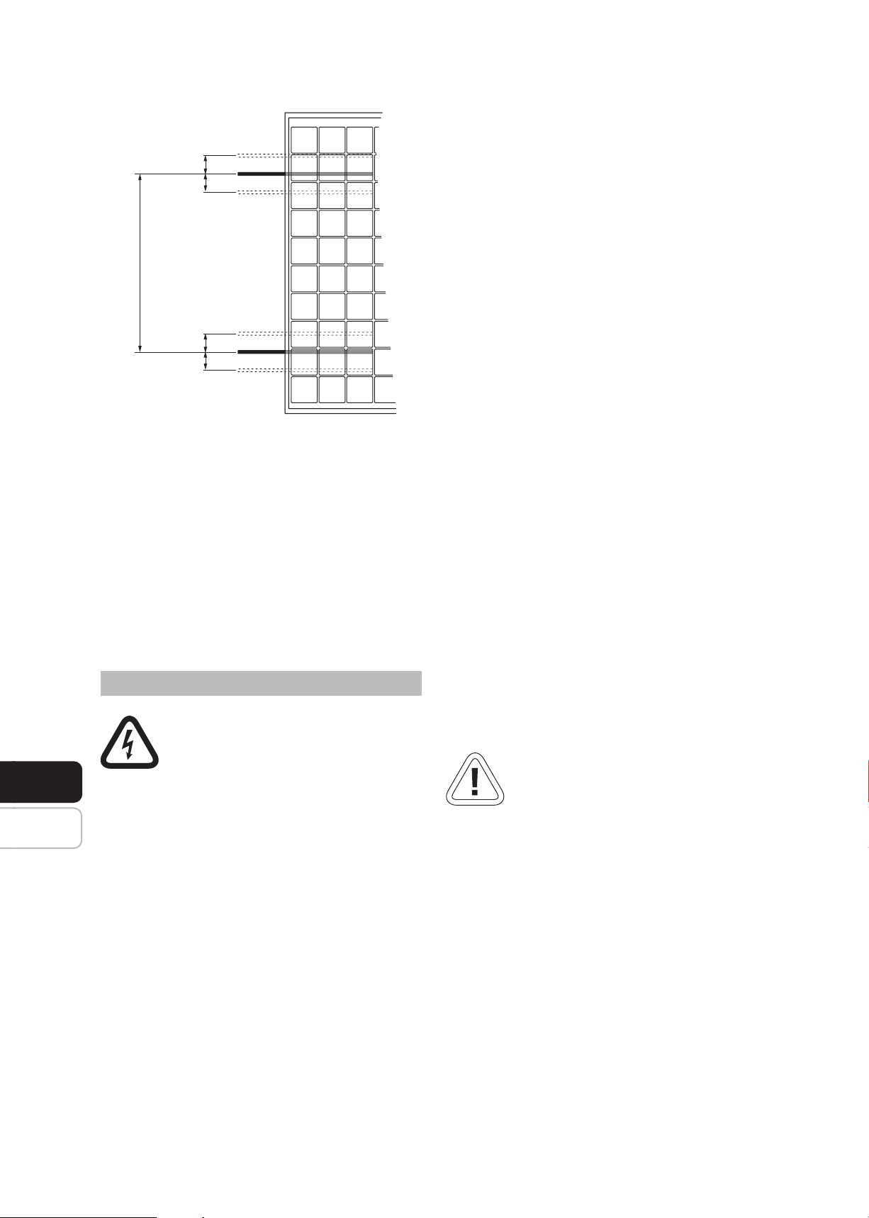
3.4 Standardbefestigung
Die Module müssen jeweils an mindestens vier
Punkten (Bohrlöcher M8 an den Längsseiten - siehe
Abbildung unter Punkt 2 Ihre Solar-Modules) sicher
befestigt werden. Der Rahmen ist für die Befesti-
gung an den Längsseiten statisch nachgewiesen, eine
Befestigung an den Schmalseiten des Moduls darf
nicht vorgenommen werden. Die maximale Abwei-
chung darf hier innen 100 mm und außen 100 mm
betragen.
Die Module wurden so konstruiert, dass diese eine
Belastung von 2400 PA durch Windkräfte (positive
wie negative Belastung) und 5400 PA durch Schnee-
belastung widerstehen.