LG PV Solar MODULE User manual

TABLEOF CONTENTS
SAFETY 03
BEFORE & AFTERINSTALLATION 05
Before Installation 05
After Installation 05
ELECTRICAL INSTALLATION 06
Danger 06
Electrical Connections 06
Diodes 06
Series Connection 06
Parallel Connection 07
General Wiring 07
Earth Grounding 07
MECHANICAL INSTALLATION 08
Module Mounting 08
Site Consideration 08
Mounting Methods 08
DISCLAIMEROF LIABILITY / DISPOSAL 10
TRANSPORTING AND STORAGE 11
REVISIONS TABLE 11
PRODUCT SPECIFICATIONS 12
Electrical & MechanicalProperties 12
Dimensions of Modules 13
APPENDIX 14
Mechanical Installation methods 14
Bolting &Clamp Information 16
Unloading Flow Guide 17

SAFETY
The instructions related to the safety indicated in the
following are for preventingunexpecteddanger or
damageinadvance by safely andexactly usingthe product.
DANGER
WARNING
CAUTION
Non-compliance of the instructions may immediately
cause serious injury or death.
Non-compliance of the instructions may cause deathor
serious injury to the user.
Non-compliance of the instructions may cause injury or
property damageto the user.
DANGER
Do not contact electrically active p
arts of the panel, such as terminal
s, without appropriate safety gear.
Contact may result in lethalspark
or electric shock.
Do not use or installif the module
is broken or torn. Failure to compl
ymay result in electric shock.
WARNING
Perform allwork in dry conditions
anduseonly dry tools. Do
not handlewet panelswithout app
ropriate protection equipment. Fail
ure to comply may result in accide
nt or death.
Damagedmodules must be treat
ed with safety protectionequipme
nt. Failure to complymay result i
nserious bodily injury or death.
No electricalparts likecables are
located afterinstallation between
laminate andmounting structure.
Do Not reconnect or repair junct
ion boxcable. It may occur spar
k or electric shock.
Do not bendingjunction box's ca
ble. While under stress, it may o
ccur module damage. Cable ben
dingradius should be more than
4times the cable diameter, at lea
st.
CAUTION
Useproper equipment, connector
s, wiresandbuttresses for the ins
tallation of the module. Failure to
comply may result in product da
mage, product failure or bodily inj
ury.
Packaged modules should be
stored inacool anddry plase.
The module packaging is not
water-weatherproof.
If stored for along time in an un
controlled environment, it can ca
use discoloration problemsof so
lar module.
Do not approachthe damaged or
brokenmodule unlessyou are an
authorized or qualified expert. Fai
lure to comply may result in serio
us bodily injury or death.
03

Do not touch the glasssurface or
frame of the solar module after in
stallation of the module. It may re
sult in injury or death.
Heavyobjects must be kept off of
the solar module.
Do not stand on or step on the m
odule. Do not dropthe module. F
ailure to comply may result in pro
duct damage, product failure or b
odily injury.
Do not scratch the coating
surface of the frame.
Scratches may decreasethe total
solar output dueto corrosion of th
eframe.
Do not artificiallyconcentrate s
unlight on the solar module sur
face. Failure to comply may re
sult in product damageor failur
e.
Do not apply a shock to the j
unction box of the module or
pullthe cable. Do not remove the
labels attachedto the module.
Failure to comply may result in
damage of the product.
If the installing modules on curved surface, (e. g. arch ty
pe), as shown in the belowpicture, do not forcefully mo
dify the module in the installation whenconnecting it wi
th the structure. Only installthe module in the place wh
erethe structure for the panelshasbeenproperly set u
p.An improper structure may cause deformation of the
panels. Panels may also be damagedby unapprovedin
stallation methods such as the use of a
Module
Installing structure
(bent type)
Module Installi
ng structure (Stral
ght type)
Product D
eformation Occurrence
of space
Partial shadow must be removed
from solar module becauseit can
cause severe problems of solar
module.
Holes in the frame or glassof
the module may decreasethe
strength of the frame or breakthe
glass.
Installation during rain, heavy wi
nd or snowy daymay result in b
odily injury or death.
crane. 4

BEFORE &AFTER INSTALLATION
BeforeInstallation
5
Please carefully read this manual beforeinstallation.
•Solar module installation andmaintenance must be
performed by qualified andauthorizedinstaller.
•All installation instructions should be read and
understoodbeforeperforminganyinstallation.
•Do not touch the solar module with barehands.
It may result inaburn or injury.
•Do not disassemblethe solar module.
•After installation or repair, check that the solar module
are operatingproperly.
•In the event that the currently usedsolar module or p
arts havebeenreplaced the newlyreplaced module a
nd parts must havethe same model nameandparts a
sthe previously installed solar module.
•In the case of adifferent model namereplacement,
AfterInstallation
•Plug in the connector tightly andensure that the wiring
properly works.
electricalcharacteristic model within 80% of the maximum •Conduct periodic inspection of the panelsfor damage
to front glass, backsheet, frame, junction box, or
externalelectricalconnections.
•Checkelectricalconnections for looseconnections
andcorrosion.
•PV panels canoperate effectively withouteverbeing washed,
althoughremoval of dirtfrom the front glasscan increase
output.
•Water, ethanol or aconventional glasscleanser with a
micro-fiber cloth can be usedfor regular washingor ri
nsing of the front glassto remove dust, dirt or other de
posits.
•Do not usegroundwater containing calcium carbonate
components whencleaning glass.
•Aggressive andabrasivecleansers or chemicals such
as alkalichemicals including ammoniabasedsolution
should not be used on cleaning the module.
•Always keep the backsurface of the panelfree from a
ny foreign objects or structural elementswhichcould c
ome into contact with the panel, especially whenthe p
anel is under mechanical load.
•Deposits of foreign material on the frame surface can
be cleaned by using a wet sponge or cloth anddried i
nair or by using a clean chamois.
•Perform the wiring work by connecting the connector
andwiresto the stand awayfrom the roof or ground.
•Do not useanykind of oil or lubricant on the module's
anyparts, It can defect the PV Module.
voltage of the system.
•Do not let anyoneapproachthe solar module whohas lit
tleknowledge of solar modules or on the measures to ta
ke whensolar modules are damagedinorder to avoid th
erisk of injury or electricalshock.
•Secure allnecessarypermitsandlicenses to install
the solar modules.
•Do not locate the solar module horizontally, as this may
cause dirt or white efflorescence(glassdeformation).
•Panels are not intendedfor useindoors or on moving
vehicles of anykind.
•Industry standard rated specifications are made at
conditions of 1000W/m2irradiance and25°C (77°F)
solar cell temperature. Colder temperatures may su
bstantially increasevoltage andpower.
•Keepthe solar moduleand system away from children
at alltimes.
•Keep the module packed in the carton untilthe time of
installation.
•Keep flammable gassesawayfrom the installation
site.
•Do not workalone. Please work as part of ateam of
two or more people.
•Safety harnessuse is strongly recommended for
installation.
•Be careful not to damagethe cable whenusing a tool s
uch as a knife to remove the cable tie that fixes the junc
tion boxcable.
•Partial shadowing may substantially reduce paneland s
ystem outputandmay be the reason for the damage of
solar module.
•Caremust be taken to avoidlowtilt angleswhichmay c
ause dirt to buildup on the glassagainst the frame edge.
•Dirt build-up on the surface of the panelmay cause a
ctive solar cells to be shaded andelectricalperforma
nceto be impaired.
it ispossible to replace an equivalent or higher

ELECTRICAL INSTALLATION
Caution
•Avoid allelectricalhazardswheninstalling, wiring,
operating andmaintaining allpanels.
•Do not connect panelsthat havedifferent electrical
properties or physicalconfigurations in the same sy
stem.
•Match the polarities of cables andterminalswhen ma
king the connections; failure to do so may result in da
mageto the panel.
•When reverse currents can exceedthe value marked
on the nameplate, aproperly rated andcertified over
-current device(fuse or circuit breaker) must be
connected in series with eachpanel or string of panels.
•The rating of the over-currentdeviceshall notexceed
the maximum series fuse rating marked on the name
plate.
•The panelcontains factory installed bypassdiodes
located inside the junction box.
•When installing the system, it isrecommended to
install a lightning rod to protect the system.
•The inducedovervoltage by lightning can cause the
system damage,you should designconductor loop
connection as minimum as possible.
•The junction boxshould not be opened. Opening the
junction boxwillvoid the warranty.
•Panels with asuspected electricalproblemshould be
returned to LG Electronics for inspection andpossible
repair or replacement as per the warrantyconditions p
rovided by LG Electronics.
Electrical Connections
•Shock hazardmay occur near the solar modules
electricalconnections.
•Modules may be connected in series and/or parallel
to achievethe desiredelectricaloutput as long as it i
swithin the guidelines on the product specification s
heet.
•Please useonly the same type of modules in a
combined source circuit.
•Do not disconnect the module under whenit is op
erating. Shock hazardmay occur near the solar m
odules connection means.
•When the module installing in series or inparallel(e.g.
usingfor extensioncables, etc.), the connectorof each
module should be the same products. (mated with its or
iginalfemale or male connector of the same supplier)
Diodes
•All LGmodules are equippedwith factory installedb
ypassdiodes. The factory-installed diodesprovide p
roper circuit protection for the module from unexpec
tedshadows.
Series Connection
•The solar modules may be wired in series to produce
the desiredvoltage output.
•The current of eachmodule connected in series
should be the same.
•The maximum number of series connected modules
can be determined by basis on maximum system volt
age, the 125%safety factor, andthe module Voc whi
ch can be checked in “Product Specifications” in this
document.
•The maximum solar module configuration can be
found in “Product Specifications”.
Series connection for more voltage
………….
Diode specification and configuration
6
UKTH3045-12
IF(AV) 30A
VF (max) 0.8V
VRRM 45V
Tj (max) 200℃
RTH 0.8℃/W
+
-
1
D 1 D 2 D3
2 3 4
5 6 7 8

Parallel Connection
•The solar modules may be combined in parallelto
producethe desiredcurrent output.
•When modules are combined in parallel,the total
current is equalto the sum of currents from each
module.
•The voltage of eachmodule connected in parallel
should be the same.
•When connecting pluralstrings of modules in parallel e
very series string or solar module must be fused prior t
ocombining with other strings.
•Abide with allapplicable federal, state, andlocalcodes
for additionalfusing requirements andlimitations on the
maximum number of solar modules in parallel.
•Maximum series fuse rating is refer to “Product
Specifications; page11”.
•Parallel configuration is notlimited if propermeasures
are taken to blockthe reverse current flow, e.g. fuses f
or the protection of the module andcables from over-
current for prevention of unbalancedstring voltage.
•LG Electronics recommends to take blocking diode
for prevention of unbalanced string voltage.
•The reverse current flow in the string may be caused by
amoduleshortcircuit,incorrectwiring,shadow,etc.
•Blocking diodes must have :
1) VRRM(Repetitive Peak Reverse Voltage) :
1.5times of maximum system voltage
2) IF (Average Forward Current) :
2times of Isc (PV module short circuit current)
※It is selected in consideration of the thermal
characteristics of the diode, and it is recommended
to use acomponent of 30mA or less for IRRM
(Repetitive Peak Reverse Current, max).
•Amultiplying factor is required for increasedoutput
of the PV modules. Under normalconditions, aPV
module is likely to experienceconditions that produce
more current and/or voltage than reported at standard
test conditions. The requirements of the National Elect
rical Code(NEC) in Article 690shall be followed to ad
dressthese increasedoutputs.
The values of Isc andVoc marked on this PV module
should be multiplied by a factor of 125%when determ
iningcomponent voltage ratings, conductor ampacitie
s, fuse sizes, andsize of controls to the PV output.
•Depending on nationaldirectives, additionalsafety fact
ors might be applicable for over current protection.
7
General Wiring
•LGElectronics recommends that allwiring be double
insulated with aminimum rating of 90°C(194°F).
•All wiring should useaflexible copper (Cu) conductor.
•The minimum size should be determined by the
applicable codes.
•LGElectronics recommends asize no smallerthan
4mm2.
Earth Grounding
•All workmust be conducted in conformance with all
Federal, State, andlocalcodes andstandards.
•Grounding worksshould be performed by an authoriz
ed installer for the safety andmaintenance of the syst
em in accordancewith allnational, state and localele
ctricalcodes andregulations andstandards.
•Specific information on the solar module dimensions a
nd location of groundingholes is provided in “Product S
pecifications”.
•One M4 stainless steel bolt, onenut, onespring wash
er, two flat washers, onecup washer, onestar washe
r and 12 AWG Cu wiresare recommended per mount
ing hole.
•Where common groundinghardware(nut, bolts, washe
rs) isusedto attach alisted groundingdevice, the attac
hment must be made in conformance with the groundi
ng devicemanufacturer’s instructions.
•All hardwareshould be consist of corrosion resistant
material such as stainless steel.
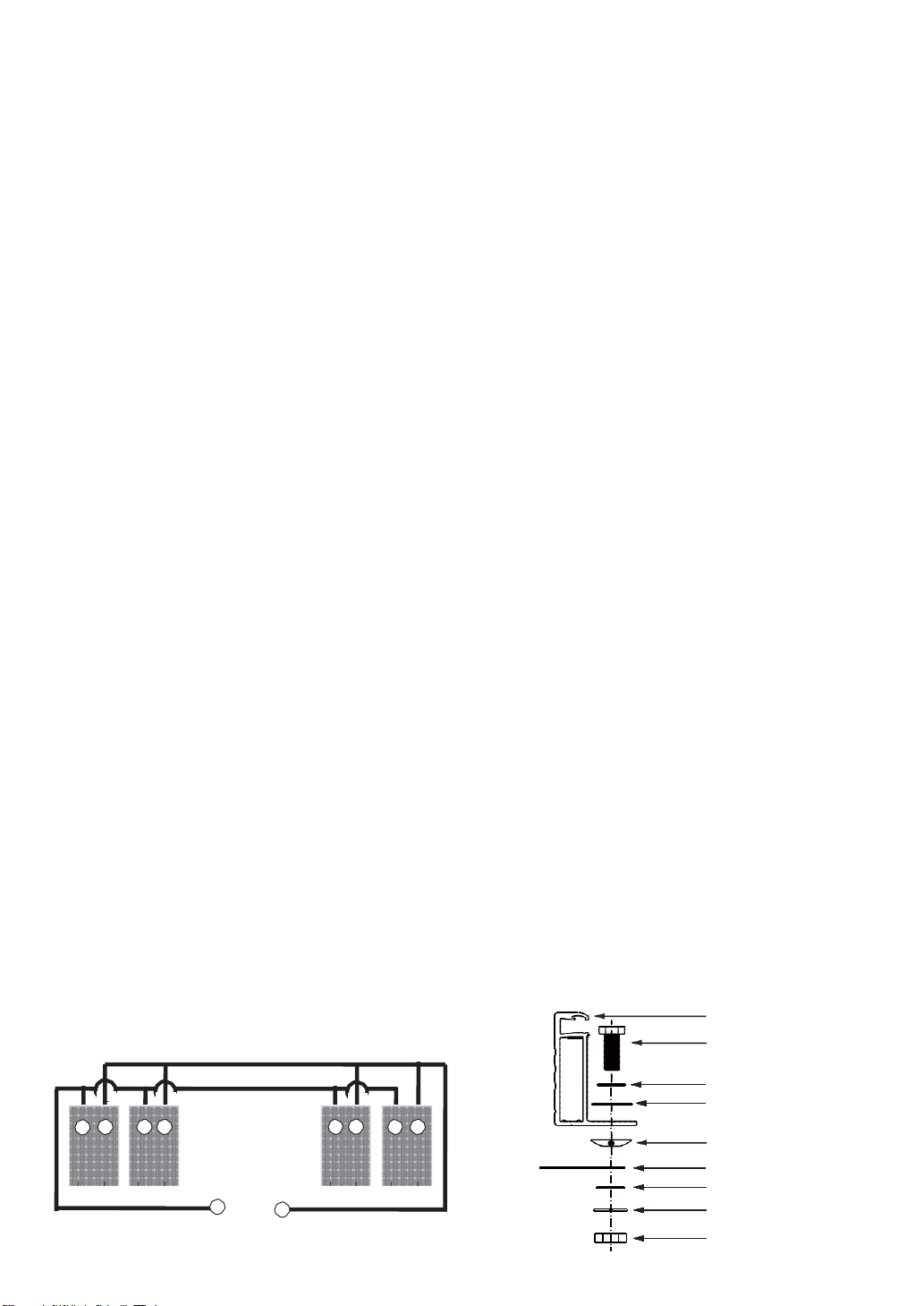
•There is an earth hole on the edge of the module f
rame. Usingthis hole, an earth conductor andthe
solar module frame may be recommended to be c
onnected andearthed as the belowdrawing.
•All screws andnutsshall be tightened to atorque of
4~5 N∙m.
•To prevent electric shock andfire, aprotective ground must
be done on the frames of solar modules andarrays althoug
hthe solar modules from LGmeet the conditions of safety
class II. The nationaldirectives must be respected.
•Bonding points to groundshould be tight, secure andfree fro
mcorrosion. (Maintenance is especially important inareas wit
hhigh levels of salt in the atmosphere, such as coastal areas
andthe surrounding seas.)
Module frame
Bolt
Flat washer
Star washer
Cupwasher
Grounding wire
Flat washer Spr
ing washer
Nut
Parallel connection for more current
…………
+ -
+-+ --
+-
+

MECHANICAL INSTALLATION
Module Mounting
•The LG Electronics’ (LGE) Limited Warranty for solar
modules is contingent uponmodules beingmounted i
naccordancewith the requirements described in this
section.
•The solar modules are in Application Class A and
havethe Safety ClassII. Therefore they can be op
erated in systems with 120V DC andhigher. Gene
ral access is not restricted.
•We recommend to usemounting device(bolt,nut,
washer)made by corrosion resistant material like
stainless steel.
Mounting
Rails
•Usecorrosion resistant material mounting rails and
hardware.
•Useappropriatebolted connections as per
manufacturer’s instructions.
•No electricalparts likecables are located after installa
tion betweenlaminateandmounting structure.
•LGEsolar module is qualified up to aaltitude of 4000m.
chimney, tree, andneighboringmodule, etc. 8
Site Consideration
LGEsolar modules should be mounted in a location that
meets the following requirements.
Module Operating Temperature
•Temperaturerange : -40°C ~ 85°C (-40°F~185°F)
•The operatingambient temperature of these devices
may exceed40℃at full load for allwire sizes if is det
erminedsuitable in the field useapplication.
Excluded Operating Environments
•The solar modules from LGElectronics can not be op
erated in a location wherethey could come in direct co
ntact with salt water or ammonia.
•Do not usemodule to replace (or partly replace) roofs
andwalls of living places.
Module Strength(Basic Load) ; IEC61215-2:2016
•Ymis a safety factor of 1.5
•Detail of mounting distance is below.
*This mounting method is by using frame bolt holes.
*The mounting rails must run perpendicularly to the module
long side.
Shadow
•LGEsolar module should be installed in a proper site
that there is no shadowing affected by building,
Mounting Methods
General Information
•Select the appropriateorientation to maximize sunlight
exposure.
The module generatesmaximum output power whenit
faces the sun directly. The tilt angle of the modules sho
uld be selected to optimizeseasonal andsunlight
-based performance in the installation place.
•Module should not be mounted or stored inawaythat
the front/top glassfaces downward in order to prevent
water from entering the junction box, whichcould caus
easafety hazard.
•Clearancebetweenthe solar module frames and stru
ctures such as roofs or ground is required to prevent
wiring damageandto allowair to circulate behindth
esolar module. The recommended standoff height is
aminimum of 100mm.
•When installed on a roof, the solar module must be mo
unted over afire-resistant roof covering rated for the a
pplication. The fire resistance of the solar module is cla
ss CafterANSI/UL790 Edition 2004.
•The solar module is only IEC listed for usewhenits
factory frame is fully intact.
•Removal or alteration must be done by an authorized
andqualified individual.
•Creatingadditionalmounting holesmay damagethe
solar module andreduce the strength of the frame.
•Werecommend a6mm gapbetweenmodule frames
to avoidtension from thermal expansion.
132Cell
(half-cut) 228mm
No.ofCell Force
Direction DesignLoad : A Test Load:B
(B = A x Ym)
132Cell
(half-cut)Front Side 3600Pascal 5400Pascal
RearSide 2650Pascal 4000Pascal

•The solar module may be mounted by usingthe
following methods: (*Torque:8~12N∙m)
•When installing modules in heavysnow areas,
it isrecommended to be taken an appropriate
countermeasure to prevent possible damagesto the
lower side frame by slipping snow.
•Werecommend to usecorrosion resistant material
for these supporting part. (A snow guardshould be
installed in accordancewith the manufacturer’s inst
ructions.)
Solar module
Supportingpart
Roof
Mounting by using frame bolts holes
•Secure the solar module to the structure by usingthe
factory mounting holes.
•Four M8 stainless steel bolts,four nuts,four spring
washers,andeightflat washersare recommended
persolar module.
•The module may be fastened to asupport by using
both the outer andinner bolt holes of the frame.
•Each module should be securely fastened at a
minimum 4points on two oppositesides.
•
andlocation of mounting holes is provided in ‘Product
•Tighten the bolt securely by usingthe combination.
Place the spring washer betweenthe Flat washer a
nd Nut.
Moduleframe
Nut
Spring washer
Flat washer
Mounting Rail
Flat washer
Bolt
* Mounting Rails Material : Aluminum, Stainless steel, etc.
Mounting by using clamps
•The module may be fastened to asupport by using
clamps on boththe long edgeandthe short edgeof
the modules.
•
provided in ‘MechanicalInstallation Scene’. (Refer to
Appendix.)
→If you use a specialclamp, it needs to test for
compatibility by LGE.
•If the installation is likely to be affected by heavy(extre
me)snow, further suitable panelsupport is recommen
ded on the lower row of panels.
09
→ We recommend more than 40x40mm mounting rails.

10
DISCLAIMEROF LIABILITY
Disclaimerof Liability
•By beginningto installation process, the installer hasto read andcompletely understandthis Installation Manual.
•If installer hadanyquestionsregarding this installation manual, the installer wouldhavecontacted LGwith any
questions or concerns.
•
lunteer andemployees, other participants in anyactivity
connected to installation,operation, or service of LGSolar Modules, andif applicable, from allliabilities, claims, dem
ands, losses, or damageson my account caused or alleged to be caused in whole or inpart by the negligence
andemployees.
Disposal
Disposal of your old appliance
1. This crossed-out wheeledbin symbol indicates that wasteelectricalandelectronic products(WEEE)
should be disposed of separately from the municipal wastestream. Please dispose of old devices se
parately from other wasteandtake them to adesignatedcollection point for electricaland electronic
waste.In case the devicescontain batteries or lampsthat can be readily removable
by end-user without damage, pleaseseparate them from the main devicesbeforedisposingthem
unlessyou want the old devicesreused (waste batteries andlampsare collected separately).
Please also notethat you are personallyresponsible for clearing personalinformation on the device
before disposing of your devices.
2. Old electricalproductscan contain hazardoussubstances so correct disposal of your old appliancewillhelp prevent
potentialnegativeconsequences for the environment andhumanhealth. Your old appliancemay contain reusable pa
rts that could be usedto repair other products, andother valuable materials that can be recycled to conserve limited r
esources.
3. You can take your applianceeither to the shop whereyou purchasedthe product, or contact your localgovernment waste
office for details of your nearest authorisedWEEE collection point. Please notethat some distributors are obliged: to take
backold devicesfrom end-usersuponselling anewequivalent equipment to them andprovidefree-of-charge collection f
or electricalandelectronic equipment of very small dimensions(not exceeding 25 cm) without the obligation for end-users
to purchasenewequipment of an equivalent type.
When distributors deliver newequipment to private households, they are obligated to collect old equipment directy f
rom them or to propose a take-back solution inareasonable distance.
Therefore, we recommend you to contact your distributor for more information.
4. LGElectronic DeutschlandGmbH is duly registered as Producer in Germany.
As such, LGcontributes to the country-wide collection andrecycling of WEEE that you bring to municipal separate
collection facility. For the most up to dateinformation pleasesee www.lg.com/global/recycling
or https://www.lg.com/de/support/altgeraete-rueckgabe
DISPOSAL

•This installation manual(Version 2.0) replaces allpreviousversions except electricalandmechanical characteristics
. For electricalandMechanical characteristics of eachmodel, pleaserefer to the Datasheet for eachmodel.
TRANSPORTINGAND STORAGE
•Do not loosenthe banding, whenthe module is transportedby truck, ship andetc. I
ncase of loosebanding, the module will be shaken, whichmay cause damage.
•Do not stack on more than onepallet. Maximum height istwo pallets. Severe stackingcan cause stress to the
module andmay cause product damage.
•Do not transport only oneside of the module whentransporting the module. Damageto the frame or cable may occur.
•Packaged modules should be stored inacool anddry plase. The module packaging is not water-weatherproof. I
f stored for along time in an uncontrolled environment, it can cause discoloration problems of solar module.
REVISIONS TABLE
11
Date Version Description of change Remark
2021.01.26 1.0 (1st edition) Publish Installation Manual
2021.08.30 2.0 (2nd edition) Update modifications [Diposal of your old appliance]

PRODUCT SPECIFICATIONS
Ratedelectricalcharacteristic except power rating within -0/+3 percent are within 5percent of measured.
Values at Standard Test Condition(STC) : Irradiance 1000W/m2, Celltemp. 25℃, 1.5AM
Note) MC4 formal name :PV-KST4 /6II-UR,PV-KBT4 /6II-UR
→ Plus (+) Connector : Male MC4 coupler (PV-KST4/6II-UR)
→ Negative(-) Connector : Female MC4 coupler (PV-KBT4/6II-UR)
Note) The Typical change in module efficiencyat 200W/m2in relation to 1000W/m2is -3.0% / ‘N3K-V6’ is -3.0%
◇Female and male cable couplers ◇
Female cable coupler
*NMOT (Nominal Module Operating Temperature) : Irradiance 800W/m 2, ambient temperature 20℃, wind speed 1m/s
Temperature Characteristics
* See more information >> http://www.multi-contact.com/ or http://en.ukt-sz.com/
Electrical Properties(NMOT*)
Ø AØ A
Male cable coupler
12
“Max. No. of modules in series” is considering125% of Voc.Actualnumberof connections
shouldbe selected accordingtothe installation site conditions and local code.
Model LGXXXN3C(W)-V6 LGXXXN3K-V6
NMOT [ °C ]42±3 42±3
Pmax [%/°C] -0.33 -0.33
Voc [%/°C] -0.26 -0.26
Isc [%/°C] 0.040.04
Model
LGXXXN3C(W)-V6 LGXXXN3K-V6
395 400 405 410 415 420 390 395 400 405 410
Maximum Power (Pmax) [W] 298 302 305 309 313 317 294 298 302 306 309
MPP Voltage (Vmpp) [V] 34.2 34.5 34.9 35.3 35.7 36.1 34.3 34.6 35.0 35.4 35.8
MPP Current (Impp) [A] 8.72 8.73 8.75 8.76 8.77 8.79 8.59 8.60 8.62 8.64 8.64
Open Circuit Voltage (Voc) [V] 42.0 42.2 42.4 42.6 42.8 43.0 42.4 42.5 42.6 42.7 42.8
Short Circuit Current (Isc) [A] 9.10 9.14 9.18 9.21 9.25 9.29 8.92 8.96 8.99 9.02 9.05
Model Cable Cross Section Ø A (Cable outer diameter) Rated current
MC4
4mm²
5.5 ~ 9mm 30A
12AWG
Electrical Properties Mechanical Properties
Module
Series Model Name Pmax
at STC
Pmax
at
Bifi100
Pmax
at
Bifi200
Power
Tolerance
Voc at
STC
Isc at
STC
Vmpp at
STC
Impp at
STC
Max.
No of
Module
In series
Max.
Series
Fuse
Rating
Max.
System
Voltage
Connector Length Width Height Weight
W W W % V A V A A V mm mm mm kg
LGXXXN3C(W)-V6
LG395N3C(W)-V6 395 395.8 396.6 0~3% 44.6 11.30 36.3 10.89 17 20 1000 MC4 1880 1042 40 19.7
LG400N3C(W)-V6 400 400.8 401.6 0~3% 44.8 11.35 36.7 10.90 17 20 1000 MC4 1880 1042 40 19.7
LG405N3C(W)-V6 405 405.8 406.6 0~3% 45.0 11.40 37.1 10.92 17 20 1000 MC4 1880 1042 40 19.7
LG410N3C(W)-V6 410 410.8 411.6 0~3% 45.2 11.44 37.5 10.94 17 20 1000 MC4 1880 1042 40 19.7
LG415N3C(W)-V6 415 415.8 416.7 0~3% 45.4 11.49 37.9 10.95 17 20 1000 MC4 1880 1042 40 19.7
LG420N3C(W)-V6 420 420.8 421.7 0~3% 45.6 11.54 38.3 10.97 17 20 1000 MC4 1880 1042 40 19.7
LGXXXN3K-V6
LG390N3K-V6 390 391.6 393.1 0~3% 45.0 11.08 36.4 10.72 17 20 1000 MC4 1880 1042 40 19.7
LG395N3K-V6 395 396.6 398.2 0~3% 45.1 11.12 36.8 10.74 17 20 1000 MC4 1880 1042 40 19.7
LG400N3K-V6 400 401.6 403.2 0~3% 45.2 11.16 37.2 10.76 17 20 1000 MC4 1880 1042 40 19.7
LG405N3K-V6 405 406.6 408.2 0~3% 45.3 11.20 37.6 10.78 17 20 1000 MC4 1880 1042 40 19.7
LG410N3K-V6 410 411.6 413.3 0~3% 45.4 11.24 38.0 10.79 17 20 1000 MC4 1880 1042 40 19.7
Note) Max. Bifaciality Coefficient of Power :N3C(W)-V6 0.04 /N3K-V6 0.06
Max. Bifaciality Coefficient of Current :N3C(W)-V6 0.05 /N3K-V6 0.07
Max. Bifaciality Coefficient of Voltage :N3C(W)-V6 0.88 /N3K-V6 0.88
Note) For information about the electrical ratings for both front and back surfaces (Bifaciality Coefficient)
and the expected contribution from ground reflected irradiance along with ground cover and installation height above ground
that reflected irradiance, please refer to the sales talk material and datasheet.

Dimensionsof Modules
Unit: mm / in.
LGXXXN3C(W)-V6 /LGXXXN3K-V6
Frame Crosssection
LongFrame Short Frame
13

14
APPENDIX
Load
Front/Rear(Pa)
Position
(mm)
0~300
890~990
A
B
1600/1600
5400/4000
Load
Front/Rear(Pa)
Position
(mm)
250 ~ 400 5400/4000
Load
Front/Rear(Pa)
Position
(mm)
250 ~ 490 5400/4000
Load
Front/Rear(Pa)
Position
(mm)
0 ~ 300 5400/1600
Load
Front/Rear(Pa)
Position
(mm)
0~50
100~750
2400/2400
A
B
Fig 1. Bolting type(M8) Fig 2. Clamping Type
Fig 4. Clamping Type
Fig 5. Clamping Type Fig 6. Clamping Type
Mechanical Installation : 66Cell Model
Load
Front/Rear(Pa)
Position
(mm)
228 5400/4000
Fig 3. Clamping Type
8

Fig 10. Clamping Type
Load
Front/Rear(Pa)
Position
(mm)
0~300
250~400
2155/2155
A
B
Load
Front/Rear(Pa)
Position
(mm)
0~300
250~400
2400/2155
A
B
Load
Front/Rear(Pa)
Position
(mm)
0~50
100~750
2400/2400
A
B
Load
Front/Rear(Pa)
Position
(mm)
250 ~ 400 4000/4000
Fig 7. Clamping Type Fig 8. Clamping Type
Fig 9. Clamping Type
APPENDIX
Mechanical Installation : 66Cell Model
Note) All mechanical installation methods and bolting method in this appendix were not tested by VDE.
It is evaluated by LG internal test.
15

16
Note) All mechanical installation methods and bolting method in this appendix were not tested by VDE.
It is evaluated by LG internal test.

17

LG Electronics Deutschland GmbH
Alfred-Herrhausen-Allee 3-5, 65760 Eschborn, Germany
Contact :service-[email protected]
LG Electronics Inc. (Global HQ)
LG Twin Towers, 128, Yeoui-daero, Yeongdeungpo-gu,
Seoul 07336, Korea
Contact: solar-svc@lge.com
http://www.lg-solar.com
This document is subject to change without notice.
LG, LG logo and Life's Good are trademarks of LG Electronics, Inc. worldwide. Trademarks and i
ntellectual properties of LG Electronics, Inc. are protected by international copyright laws.
This manual suits for next models
11
Table of contents
Other LG Solar Panel manuals

LG
LG LGXXXQ1C-A6 User manual

LG
LG LG N1C-G4 Series User manual

LG
LG LG N1C(W)-E6 Series User manual

LG
LG LGxxxN1CW-A3 Series User manual

LG
LG LGxxxS1C(W User manual

LG
LG LG A1C-V5 Series User manual

LG
LG LG N1C-N5 Series User manual

LG
LG LG270N1C(W)-G3 User manual

LG
LG LG240M1C User manual

LG
LG MonoX ACe User manual

LG
LG LG Q1K-V5 Series User manual

LG
LG LG N9C-G4 Series User manual

LG
LG Neon 2 S1C L4 Series User manual

LG
LG LG N2T-J5 Series User manual

LG
LG LG S1C-A3 Series User manual

LG
LG LG S1C-L4 Series User manual

LG
LG N1T-G4 Series User manual

LG
LG LG345Q1C-A5 User manual

LG
LG LG280N1CW-G4 User manual

LG
LG N1T-A5 Series User manual