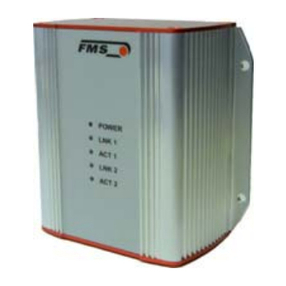
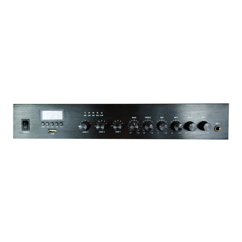
Solartron Analytical Power Booster System EXTBOOST50V5A User manual

Power Booster
System
USER GUIDE

Solartron Analytical UK
5 Ashville Way, Molly Millars Lane,
Wokingham, Berkshire, RG41 2PL, UK
Tel +44 (0) 1252 556 800
Email: [email protected]
Web: http://www.ameteksi.com
For details of our agents in other countries, please contact our UK office.
Solartron Analytical pursues a policy of continuous development and product improvement.
The specification in this document may therefore be changed without notice.

14906001_AA 12-09-07 iii


14906001_AA 12-09-07 v
GENERAL SAFETY PRECAUTIONS
The equipment described in this manual has been designed in accordance ith
EN61010 "Safety requirements for electrical equipment for measurement, control
and laboratory use", and has been supplied in a safe condition. To avoid injury to
an operator or service technician the safety precautions given belo , and
throughout the manual, must be strictly adhered to, henever the equipment is
operated, serviced or repaired. For specific safety details, please refer to the
relevant sections ithin the manual.
The equipment is intended solely for electronic measurement and should be used for
no other purpose. Solartron accept no responsibility for accidents or damage resulting
from any failure to comply ith these precautions.
GROUNDING
To minimise the hazard of electrical shock, it is essential that the equipment be
connected to a protective ground through the ac supply cable. The continuity of
the ground connection should be checked periodically.
AC SUPPLY OLTAGE
Never operate the equipment from a line voltage or frequency in excess of that
specified. Other ise, the insulation of internal components may break do n and
cause excessive leakage currents.
FUSES
Before s itching on the equipment check that the fuses accessible from the
exterior of the equipment are of the correct rating. The rating of the ac line fuse
must be in accordance ith the voltage of the ac supply.
Should any fuse continually blo , do not insert a fuse of a higher rating. S itch
the equipment off, clearly label it "unserviceable" and inform a service technician.
EXPLOSI E ATMOSPHERES
You must NEVER OPERATE the equipment, or any sensors connected to the
equipment, in a potentially explosive atmosphere. The equipment is NOT
designed for use in these conditions and could possibly cause an explosion.
SAFETY SYMBOL
For the guidance and protection of the user, the follo ing safety symbol appears
on the equipment:
Symbol Meaning
Refer to operating manual for detailed instructions of use. In
particular, note the maximum voltage permissible at the input
sockets, as detailed in the Specification.
Continued overleaf.
!

vi 14906001_AA 12-09-07
General Safety Precautions (continued from previous page)
NOTES, CAUTIONS AND WARNINGS
For the guidance and protection of the user, Notes, Cautions and Warnings
appear throughout the manual. The significance of these is as follo s:
NOTES
highlight important information for the reader’s special attention.
CAUTIONS
guide the reader in avoiding damage to the equipment.
WARNINGS
guide the reader in avoiding a hazard that could cause injury or
death.
A OID UNSAFE EQUIPMENT
The equipment may be unsafe if any of the follo ing statements apply:
• Equipment sho s visible damage.
• Equipment has failed to perform an intended operation.
• Equipment has been stored in unfavourable conditions.
• Equipment has been subjected to severe physical stress.
If in any doubt as to the serviceability of the equipment, don't use it. Get it
properly checked out by a qualified service technician.
LI E CONDUCTORS
When the equipment is connected to its measurement inputs or supply, the
opening of covers or removal of parts could expose live conductors. The
equipment must be disconnected from all po er and signal sources before it is
opened for any adjustment, replacement, maintenance or repair. Adjustments,
maintenance or repair must only be done by qualified personnel, ho should
refer to the relevant maintenance documentation.
EQUIPMENT MODIFICATION
To avoid introducing safety hazards, never install non-standard parts in the
equipment, or make any unauthorised modification. To maintain safety, al ays
return the equipment to your Solartron service provider for service and repair.
HANDLING AND CARRYING
Take care hen handling and carrying heavy equipment. Follo the
manufacturer’s instructions, and ask for assistance if necessary.

Booster User Guide
14906001_AA 12-09-07 vii
Contents
1. INTRODUCTION .............................................................................................. 1-1
1.1 THEORY OF OPERATION......................................................................... 1-2
1.1.1 Measurement Scaling ...................................................................... 1-4
2. INSTALLING THE UNIT ................................................................................... 2-1
2.1 CHECKING THE ACCESSORIES.............................................................. 2-1
2.2 SITING THE BOOSTER ............................................................................. 2-2
2.3 CONNECTING THE AC SUPPLY .............................................................. 2-2
2.4 CONNECTING THE BOOSTER TO A 128 SERIES POTENTIOSTAT.... 2-3
2.4.1 Potentiostat Connections ................................................................. 2-3
2.4.2 Remote Control Connections........................................................... 2-3
2.5 CONNECTING THE BOOSTER TO THE CELLTEST SYSTEM................ 2-4
2.5.1 Boosted Channel Connections ........................................................ 2-4
2.5.2 Remote Control Connections........................................................... 2-5
2.5.3 Assembling the Booster Control Cable ............................................ 2-6
2.6 CONNECTING THE BOOSTER TO THE LOAD........................................ 2-7
3. RUNNING AN EXPERIMENT ........................................................................... 3-1
3.1 BOOSTER STATUS INDICATORS............................................................ 3-2
3.2 OVERLOAD AND TEMPERATURE SHUTDOWNS .................................. 3-2
3.3 EMERGENCY STOP.................................................................................. 3-4
3.3.1 Remote Emergency Stop................................................................. 3-4
4. POWER AND HEAT MANAGEMENT .............................................................. 4-1
4.1 BOOSTER VARIANTS ............................................................................... 4-1
4.1.1 Booster Variant 5 V/25A/125W ....................................................... 4-2

Contents
Booster User Guide
viii 14906001_AA 12-09-07
5. IMPEDANCE MEASUREMENT........................................................................5-1
5.1 BIAS .......................................................................................................5-1
5.2 POTENTIOSTAT/GALVANOSTAT BANDWIDTH......................................5-1
5.3 INTEGRATION TIME..................................................................................5-2
5.4 RANGE/AUTORANGE ...............................................................................5-2
5.5 MAINS HARMONICS..................................................................................5-2
6. SYSTEM SPECIFICATION...............................................................................6-1
6.1 MODELS.....................................................................................................6-1
6.2 ELECTRICAL..............................................................................................6-1
6.2.1 Impedance Measurement Accuracy................................................. 6-2
6.3 MECHANICAL ............................................................................................6-2
6.4 ENVIRONMENTAL .....................................................................................6-2
6.5 STANDARDS..............................................................................................6-2
7. INDEX ...............................................................................................................7-1
Figure - Front panel view of the power booster............................................................. -
Figure -2 Rear panel controls on the power booster. ...................................................... -2
Figure -3 Load connections: a) two-terminal, b) three-terminal, c) four-terminal. ............ -2
Figure -4 Block schematic of the power booster operation. ............................................ -3
Figure 2- Booster control cable for 280 series instruments. ..........................................2-3
Figure 2-2 Boosted channel connection to the CellTest....................................................2-4
Figure 2-3 Connecting the remote control cable between the CellTest and the booster. ..2-5
Figure 2-4 Pin numbering of the CellTest Control Output connectors. ..............................2-6
Figure 2-5 Pin numbering of 9-way D plug for booster REMOTE input.............................2-6
Figure 2-6 Booster output socket......................................................................................2-7
Figure 3- Front panel controls of the booster. .................................................................3-
Figure 3-2 Booster control cable with emergency stop switch ..........................................3-4
Figure 4- Continuous discharge voltage and current for 50V/25A/ 25W booster............4-2

Booster User Guide
Contents
14906001_AA 12-09-07 ix
Table 2- Interconnection Cable Set for the 280 Series................................................. 2-
Table 2-2 Interconnection Cable Set for the CellTest System .......................................... 2-
Table 2-3 CellTest Booster Control Outputs..................................................................... 2-6
Table 4- Operating Ranges of Booster Variants............................................................. 4-


Booster User Guide
14906001_AA 12-09-07 1-1
. Introduction
The Po er Booster is a standalone high po er amplifier that increases the voltage
and current drive capability of potentiostat and galvanostat instruments, to
provide testing of high po er fuel cells, batteries and supercapacitors.
Figure 1-1 Front panel view o the power booster.
The unit is available in several variants that cover a range of voltage and current
drive/sink capabilities. These comprise:
Booster 12V/20A −3V to +12V at ±20A
Booster 24V/10A −3V to +24V at ±10A
Booster 50V/5A −3V to +50V at ±5A
Booster 50V/25A/125W −3V to +50V at –25A to 0A, subject to
maximum po er limitations
Booster 100V/3A −3V to +100V at ±3A
The experiment safety limits for boosted drive channels should be set in
accordance ith the boosted values. When setting the current limits, allo a
generous margin of safety.

Introduction
Booster User Guide
1-2 14906001_AA 12-09-07
Figure 1-2 Rear panel controls on the power booster.
1.1 THEORY OF OPERATION
The po er booster is an amplifier built to interface directly ith
potentiostat/galvanostat instruments. This section describes the ay in hich the
booster inter-acts ith these instruments.
The main function of a potentiostat is to apply a defined voltage to a load and to
measure the resulting current through it. Similarly, a galvanostat maintains a
defined current through a load and measures the resulting voltage across it. To
perform these tasks, the potentiostat/galvanostat plus booster can be connected to
t o, three or four-terminal cells. (See Figure 1-3.)
Potentiostat
+ Booster
RE1
CE
WE
RE2
Potentiostat
+ Booster
CE
WE
RE1
RE2
a) b)
c)
Potentiostat
+ Booster
RE1
CE
WE
RE2
Figure 1-3 Load connections: a) two-terminal, b) three-terminal, c) our-terminal.

Booster User Guide
Introduction
14906001_AA 12-09-07
1-3
The reference electrode connections RE1 and RE2 enable measurement of the
voltage across the cell (or the part of the cell that is of interest), thus eliminating
from the measurements the ohmic drop due to the CE and WE cable connections.
To be able to interface directly ith a potentiostat, and thus enable higher current
and voltages to be applied to the load, the booster has the internal structure
outlined in Figure 1-4. The
×
××
×10
amplifier multiplies the voltage applied to its
input by a factor of 10 and applies it to the load. The resulting current I
Load
is
sensed by the current sense circuit, hich outputs to the potentiostat a scaled
do n current proportional to the current through the load. This determines the
current flo ing at the input of the po er booster such that I
Input
= I
Load
/1000. The
load voltage across the sensing electrodes is 10 times that output by the
potentiostat, so a 1/10 divider scales this voltage do n to the level compatible
ith the reference inputs of the potentiostat. The net result is that the potentiostat
“sees” hat is happening to the load, scaled do n by given scaling factors. The
potentiostat control loop drives the booster input as though it ere the load,
measuring and controlling as usual, hile the load experiences 10 times the
voltage and 1000 times the current.
Figure 1-4 Block schematic o the power booster operation.

Introduction
Booster User Guide
1-4 14906001_AA 12-09-07
1.1.1 MEASUREMENT SCALING
When enabled, the booster increases the output voltage of a potentiostat by a
factor of 10 and the output current by a factor of 1000. For example, if you set
your potentiostat to output a potentiostatic drive of 2V the booster increases this
to 20V. Similarly, if you set up a galvanostatic current of 5mA the booster
increases this to 5A.
Drive scaling must be considered hen using the booster and interpreting the
results. If proprietary soft are such as CellTest, MultiStat, Zplot and CorrWare
1
is used to control the potentiostat, the scaling is taken care of and the
voltage/current that is programmed is the voltage/current imposed on the cell;
other ise the PC must be programmed accordingly to include the scaling factors.
Note that ith CellTest, the scaled-up values are used hen the experiment limits
are set up for a boosted channel. Ho ever, the boosted channels must be grouped
into one experiment and the non-boosted channels into another. Boosted and
non-boosted channels must not be used together in the same experiment.
1
These po er boosters have an asymmetric voltage output range that is optimised for energy storage
applications (the CE output can deliver a voltage in the range of -3V to the positive limit for the particular
booster, e.g. +24V). Ho ever, some electrochemical tests require a ider voltage range in the opposite polarity.
This can be achieved by reversing the connections to the cell. If using MultiStat, Zplot or CorrWare soft are,
the polarity convention in the cell setup menu can then be configured to display voltage and current in the
preferred sign convention.

Booster User Guide
14906001_AA 12-09-07 2-1
2. Installing the Unit
To ensure that the booster operates safely and satisfactorily ithin its
specification, install the unit as described belo .
2.1 CHECKING THE ACCESSORIES
A full set of cables should accompany the booster. Check to see that there is a
full set of the correct cables as follo s:
• A t o-metre cable for connecting the booster to the ac supply. This is
described in Section 2.3.
• A set of cables for connecting the booster to the load. These ill consist of a
pair of heavy gauge cables to be connected to the load ‘+’ and ‘–’ terminals,
used for carrying the high current through the load, and a pair of finer gauge
cables for load voltage sensing. The use of these cables is described in
Section 2.6.
• T o sets of cables are provided for connecting the booster to the potentiostat.
These are:
• One set of cables for connection to a unit in the 1280 Series.
See Table 2-1 belo and Section 2.4.
• One set of cables for connection to a CellTest System.
See Table 2-2 belo and Section 2.5.
Table 2-1 Interconnection Cable Set or the 1280 Series
Cable Connection Connectors on 1280
Series Units
Connectors on
Booster
1
2
3
4
CE:
WE and Lo:
RE1:
RE2:
BNC
BNC and banana plug (Lo)
BNC
BNC
These four
connections made
to 25-way ‘D’-type
on the rear panel.
5 REMOTE: BNC 9-way ‘D’-type on
the rear panel.
Table 2-2 Interconnection Cable Set or the CellTest System
Cable Connections
1
2
CE, WE, RE1, RE2, Lo: 15-way ‘D’-type on CellTest to 25-way
‘D’-type on booster
REMOTE: The provided 9-pin D-type connector should be
connected to the 25-way ‘D’-type connector that is provided with the
147 3 Control Output option. (See Section 2.5.3.)

Installing the Unit
Booster User Guide
2-2 14906001_AA 12-09-07
2.2 SITING THE BOOSTER
When choosing the site, remember the po er level of the booster and act
accordingly. Do not use the unit near flammable materials.
Allo space around the booster for air circulation. To cool the unit, fan assisted
ventilation takes air in through the front panel and expels it from the rear.
Remember that at full po er the heat produced is around 500W, and small rooms
ithout appropriate ventilation must be avoided.
The unit is intended for laboratory and clean environments.
2.3 CONNECTING THE AC SUPPLY
The booster is fitted ith a universal po er supply, suitable for connection to any
mains ac voltage in the range 90V to 264V. The fuses are 8AT (8 amp slo
blo ), suitable for any voltage ithin this range.
A t o-metre po er cable ith a suitable plug is provided for connection to the ac
supply. The supply should be left s itched off until all other connections are
made and the unit is ready for use.
Ensure appropriate grounding of the unit, and of all the instruments and loads to
be connected to it, to avoid shorts and floating potentials.

Booster User Guide
Installing the Unit
14906001_AA 12-09-07
2-3
2.4 CONNECTING THE BOOSTER TO A 1280 SERIES
POTENTIOSTAT
2.4.1 POTENTIOSTAT CONNECTIONS
On potentiostats such as the 1280, 1285 and 1287, the
CE
,
WE
,
RE1
and
RE2
, and
Lo
connectors connect to a single 25- ay ‘D’ type connector on the booster rear
panel. (The circular multi ay connectors on the front panel are reserved for other
use.)
NOTE: The banana plug connector
on the
Lo
cable goes to the potentiostat,
here it should be inserted into the
Lo
terminal.
2.4.2 REMOTE CONTROL CONNECTIONS
The
REMOTE
connector on the booster enables the unit to be automatically
connected and disconnected from the load at the start and end of the experiment.
The load is connected hen pins 4 and 5 are shorted. This can be done from the
BOOSTER CONTROL
output on a unit such as the 1280, 1285 and 1287. Details
of the cable supplied for this purpose are sho n in Figure 2-1.
Figure 2-1 Booster control cable or 1280 series instruments.
See also Figure 3-2, Section 3.3.1, for a version of this cable that includes a
remote emergency stop s itch.
NOTE: Contact the Service Department at Solartron if the potentiostat does
not have a booster control output connection on the rear panel.

Installing the Unit
Booster User Guide
2-4 14906001_AA 12-09-07
2.5 CONNECTING THE BOOSTER TO THE CELLTEST SYSTEM
2.5.1 BOOSTED CHANNEL CONNECTIONS
A cable is provided for connecting a
MAIN
channel on the CellTest unit to the
CellTest
connector on the booster rear panel. This cable carries the connections
for CE, RE1, RE2, Lo, and WE. See Figure 2-2.
Figure 2-2 Boosted channel connection to the CellTest

Booster User Guide
Installing the Unit
14906001_AA 12-09-07
2-5
2.5.2 REMOTE CONTROL CONNECTIONS
The
REMOTE
connector on the booster enables the unit to be remotely controlled
for connecting the load in or out of the circuit at the booster po er output. The
load is connected hen pins 4 and 5 on the
REMOTE
connector are shorted. This
is done from the
Control Output
connectors on the CellTest unit rear panel. See
Figure 2-3.
Figure 2-3 Connecting the remote control cable between the
CellTest and the booster.
For the CellTest unit to e a le to control a ooster, it must e fitted with
Option 14703A. This provides a set of control outputs for each main channel.
For each of these channels, one control output in the set is dedicated to
controlling the booster. Note that the remote control cable must be configured for
the CellTest channel that has the booster, therefore this cable is not supplied pre-
configured. The control output connections are described in Section 2.5.3 belo .

Installing the Unit
Booster User Guide
2-6 14906001_AA 12-09-07
2.5.3 ASSEMBLING THE BOOSTER CONTROL CABLE
The control cable should be assembled in accordance ith the channel for hich
it is to be used. See Table 2-3 and Figures 2-4, 2-5 for details. Note that the
control connections to the 25-pin ‘D’-type socket are different for each channel.
There are three control outputs per channel (defined on the user interface as
Outputs ‘A’, ‘B’ and ‘C’) making 24 altogether, but the one for booster control is
al ays Output ‘C’: this is determined by the firm are and is fixed.
Note from Table 2-3 that the control output pin assignments for channels 1 to 4
(on the lo er control output connector) is repeated for channels 5 to 8 (on the
upper control output connector).
Table 2-3 CellTest Booster Control Outputs
Channel 1 2 3 4 5 6 7 8
Control O/p ‘C’ Hi 23 2 17 14 23 2 17 14
Control O/p ‘C’Lo 11 8 5 2 11 8 5 2
Pin numbering of mating connectors, as
viewed from rear of connector.
CHANNELS 5 - 8
CHANNELS 1 - 4
CONTROL OUTPUT
CONNECTORS
MAX RATING
50V / 100mA
131
2514
Figure 2-4 Pin numbering o the CellTest Control Output connectors.
Figure 2-5 Pin numbering o 9-way D plug or booster REMOTE input.
This manual suits for next models
5
Table of contents
