Solartronics FS Series User manual
1
E N
N L
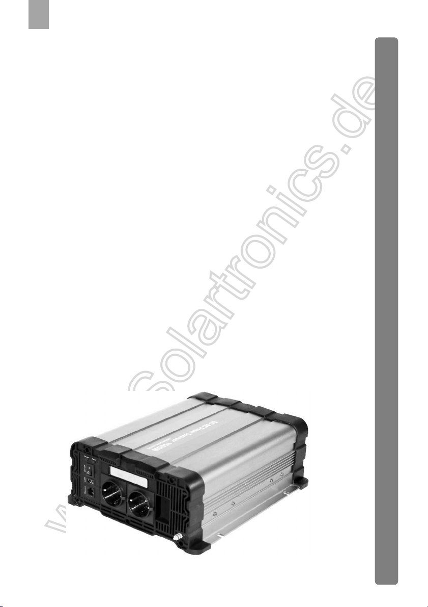
FS&NK series
pure sine wave power inverter
DC
-
AC INVERTER
Available models:
FS600 FS1000 FS1500 FS2000 FS2500 FS3000
FS4000
2
E N
N L
1. Explanation of symbols
DANGER!
Safety instruction: Failure to observe this instruction will cause fatal or serious injury.
User s manu a l
P a g e 2 - 1 9
Gebr a u chsa n w e is u n g
S e i t e 2 0 - 3 7
Me c h a n i c a l d r a w i n g s / A b mess u n g e n
Pa g e / S e i t e 3 8 - 4 2
E N
D E
3
E N
N L
WARNING!
Safety instruction: Failure to observe this instruction can cause fatal or serious injury.
NOTICE!
Failure observe this instruction can cause material damage and impair the function of the
product.
NOTE
Supplementary information for operating the product.
2. General safety instructions
2.1 General safety
The manufacturer accepts no liability for damage in the following cases:
. Faulty assembly or connection
. Damage to the product resulting from mechanical influences and incorrect connection voltage
. Alterations to the product without express permission from the manufacturer
. se for purposes other than those described in the operating manual
Note the following basic safety information when using electrical devices to protect against:
.Electric shock
. Fire hazards
. Injury
2.2 General safety

4
E N
N L
DANGER!
. In the event of fire, use a fire extinguisher which is suitable for electrical devices.
WARNING!
. Only use the device as intended.
. Ensure that the red and black terminals never come into contact.
. Disconnect the device from the power supply:
- Before cleaning and maintenance
- Before changing a fuse
. If you disassemble the device:
- Detach all connections
Make sure that no voltage is present at any of the inputs and outputs
. The device may not be used if the device itself or the connection cable are visibly
damaged.
. If this power cable for this device is damaged, it must be replaced by the manufacturer,
customer service or a similarly qualified person in order to prevent safety hazards.
. This device may only be repaired by qualified personnel. Inadequate repairs may cause
serious hazards.
. This device can be used by children aged 8 years or over, as well as by persons with
diminished physical, sensory or mental capacities or a lack of experience and/ or
knowledge, providing they are supervised or have been taught how to use the device
safely and are aware of the resulting risks.
. Electrical devices are not toys.
Always keep and use the appliance out of the reach of children.
. Children must be supervised to ensure that they do not play with the device.
NOTICE!
. Before start-up, check that the voltage specification on the type plate is the same as that
of the power supply.
. Ensure that other objects cannot cause a short circuit at the contacts of the device.
. Never pull the plug out of the socket by the connection cable.
5
E N
N L
. Store the device in a dry and cool place.
2.3 Safety when installing the device
DANGER!
. Never mount the device anywhere where there is a risk of gas or dust explosion.
CAUTION!
. Ensure that the device is standing firmly.
The device must be set up and fastened in such a way that it cannot tip over or fall down.
NOTICE!
. Do not expose the device to a heat source (such as direct sunlight or heating). Avoid
additional heating of the device in this way.
. Set up the device in a dry location where it is protected against splashing water.
2.4 Safety when connecting the device electronically
DANGER! Danger of electrocution
. If you are working on electrical systems, ensure that there is somebody close at hand
who can help you in emergencies.
WARNING!
. Make sure that the lead has a sufficient cross-section.
. Lay the cables so that they cannot be damaged by the doors or the bonnet.
Crushed cables can lead to serious injury.
CAUTION!
. Lay the cables so that they cannot be tripped over or damaged.
NOTICE!
. se duct-work or cable ducts if it is necessary to lay cables though metal panels or
other panels with sharp edges.

6
E N
N L
. Do not lay the 230 V mains cable and the 12 V DC cable in the same duct.
. Do not lay the cable so that it is loose or heavily kinked.
. Fasten the cables securely.
. Do not pull on the cables.
2.5 Operating the device safely
DANGER! Danger of electrocution
. Do not touch exposed cables with your bare hands.
WARNING!
Only use the device in closed, well-ventilated rooms.
CAUTION!
. Do not operate the device
- In salty, wet or damp environments
- In the vicinity of corrosive fumes
- In the vicinity of combustible materials
- In areas where there is a danger of explosions.
. Before starting the device, ensure that the power supply line and the plug are dry.
. Always disconnect the power supply when working on the device.
. Please observe that parts of the device may still conduct voltage even if the fuse has
blown.
. Do not disconnect any cables when the device is still in use.
NOTICE!
. Make sure the air inlets and outlets of the device are not covered.
. Ensure good ventilation.

7
E N
N L
3. INTRODU TION
Read this user manual completely before using the device. In the appendices you will find the
technical specifications of the pure sine wave power inverters.
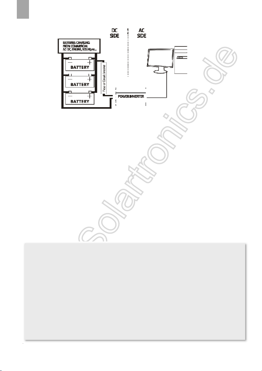
This DC-AC inverter converts a 12 or a 24 Volts DC voltage into a AC voltage with a pure sine
wave (100-127V/220-240VAC). With this device it is possible, with use of the right battery, to
supply equipment that normally requires a mains supply.
Important
Always check the actual power rating of the equipment (power consumption). In addition, bear
in mind the surge powers. hese (start-up) peaks can be as much as 5-7 times the continuous
power consumption. Check whether these values are within the capacity limits of the inverter.
Equipment with high surge power are for example: air conditioning, vacuum cleaner, tools and
pumps. If you want to use multiple equipment at the same time, then add up the power
consumption.
4. INSTALLATION
4.1 Mounting
The inverter must be mounted in a space that complies with the following:
-
Mount the inverter in a dry place where there is no chance of it being affected by moisture or
dirt. Also be aware of moisture or dirt that can be sucked in by the fan.
-
Leave enough space on all sides of the inverter (min. 10cm) for air circulation. Make sure that
there are ventilation vents.
-
The ambient temperature must be between 0ºC and 40ºC. Ideal is between 15ºC and 25ºC.
-
Keep the inverter out of the reach of children.
-
A working inverter produces a dangerous voltage.
-
Do not use the inverter in places where gases are released or flammable materials are stored.

8
E N
N L
-
The distance between inverter and battery should be as short as possible, but place the inverter
in a separate room.
-
Place the inverter on a stable underground and prevent (heavy) vibrations and shocks.
4.2 Connection with the attery
Important
- Before connecting to the battery, make sure that the inverter is turned off.
- When the battery is connected a spark may be generated due to the internal capacitor being
loaded.
Preferably use the supplied battery cable set. If you want this inverter to have a permanent
connection to the battery, we recommend replacing the clamps with terminal rings. For the other
models, the connections to the battery already consist of terminal rings. With the models
FS2500&NK2500 and FS3000&NK3000 two red and two black cables are included. In this case,
always connect both cables on the + and - side!
If you wish to use an own cable set, keep the cables as short as possible and ensure the connections
make good contact. Below formula indicates the required cable thickness
(Watt/voltage) x length in meters x 0,2 = cable in mmq
Example (1500W/12V) x 2 meters x 0,2 = 50mmq
Working method:
1.
Connect the cables to the inverter first:
the red cable to the red + input connection. The black cable to the black – input connection.
Tighten the connections firmly.
2.
Connect the other side of the cable to the battery:
The red cable to the + pole of the battery. The black cable to the – pole of the battery.
Important
Make sure that you connect the correct cable to the correct pole! he inverter can become
broken in this case. he repair costs are not covered by the guarantee.

9
E N
N L
Grounding
The AC output ground wire should be connected with the grounding point for the connected
equipment. Also wire the ‘ground’ connection on the inverter with the chassis of the vehicle or
the minus (6mmq wire).
4.3 Connection with the equipment
All inverters from the FS&NK series have a socket for the connection of the 110/230VAC
equipment. The models from 1500Watt have double sockets.
When connecting multiple users it is important that the total load (Watts) and surge powers fall
within the capacity specifications of the inverter.
Important
-
If the surge power is exceeded, the inverter will become heavily damaged. Repair costs will
not be covered by warranty.
-
Don’t mount the cables against the housing of the inverter.

10
E N
N L
4.4 The inverter in com ination with other AC power supplies
In many situations it is desirable that the equipment will work on the mains supply (or
generator) when this is available. The inverter and mains supply (or generator) then become one
circuit. Pay attention to the following:
Important
At the presence of a second power supply (mains, generator) this 110/230VAC will be parallel
on the output of the inverter. his will damage the inverter heavily!. he repair costs are not
covered by warranty. If you want the equipment to work on both an inverter and a second power
source, then mount the power transfer switch. Important feature is that this power transfer
switch is bipolar.
The power transfer box takes care of automatic switch between the two 110/230VAC circuits,
without any intervention for the connected equipment. A back-up system also can be created this
way.
11
E N
N L
4.5 Insulation monitoring
Is this inverter being mounted in a vehicle of any other mobile or movable unit? And is the
110/230VAC going to be used outside the vehicle/unit? Then please pay attention to the
following:
Important
!
If this inverter is used in mobile unities, like mobile workplaces, fire trucks, workmen’s huts
etc, it is usually difficult to get a good and reliable safety connection to earth. However, by law
it is
obligated
to make sure that a person can use an inverter or mobile generator safely. If the
inverter is mounted inside vehicle/unit, and one goes to work outside the vehicle/unit with the
connected 110/230VAC equipment, then it is mandatory to mount an insulation monitoring
device. An RCD (not any type!) will not meet! When an accident occurs because an insulation
monitoring device isn’t mounted in the system, it has serious consequences. In these situations,
always mount an insulation monitoring device from our ISO-series between de inverter and
equipment. For more info, please visit our website www.xenteq.nl. he law applies to all
vehicles/mobile units that are use professionally. Caravans, mobile homes etc. are excluded
from this law, however the circumstances are identical.

12
E N
N L
5. IN USE
Check that the cables are mounted correctly. Never use the inverter when the cables are
damaged.Set the power switch to “ON” position.
A warm housing is normal when the inverter is operating.
I you will not be using the inverter or a signi icant period (during winter storage or example), we
recommend disconnecting it rom the battery.
5.1 LED indications (FS series )
‘power’ (green) Battery connected and the on/o switch is in ‘on’ position
‘ ault’ (red) Fault occurred on the input side or internal temperature
‘ ault’ (red, blinking) Fault occurred on the output side.
In cause o a ault, consult the chapter ‘protections’ and the trouble shooter.
5.2 LED Indications (NK series)
“Level load” (3 colors) when loading with 20% rated power, led not light; when loading up to 20-
50% rated power, LED green; when loading up to 50-75% rated power, LED orange; when ull load
up to 80-100%, LED red
“Status “ (2 colors) battery connected and the o /o switch is in “on “ position, LED green;
When inverter protection unction occurred or ault occurred.
5.3 Dip Switcher (NK series only )
S4 - 50/60Hz adjustable (I on position means 60Hz, O o position means 50Hz)

13
E N
N L
S3- Sleeping mode activated, i load less 5% o rated power. e.g: 2000w less 100w then
S2- Sleeping mode activated, i load less 10% o rated power.
S1- Sleeping mode activated, i load less 15% o rated power.
5. USB output
All models have an USB port. Here you can connect your 5Volt users, like mobile phone charger,
directly. The maximum load or this output is 2,1Amp.
5.5 Remote control
I the remote controller CR80 or CRD80 or CRW80 is connected, it is important that the main
switch o the inverter is in the ‘o ’ position. A ter this, the inverter can be switched on and o by
using the remote control.
5.6 LCD display function (optional)
It displays the battery voltage(V), output power(W) , battery capacity( Ah), lower voltage
protection, over voltage protection, over load protetcion, over temperature protection.
5.7 Fan
The an is both temperature- and load controlled. At a certain load level, depending per model,
the an will switch on automatically. Also at an internal high temperature the an will switch on
automatically.
What does the inverter consume from the battery?
A quick ormula which gives a global indication o the current draw rom the battery is:
Watt : voltage = current draw per hour
Example: a 1500Watt inverter in 12Volt consumes at ull load:
1500W : 12V = 125Amp. per hour. Has the inverter delivered this power or 5 minutes, then
the current draw rom the battery is about 10Amp per hour.
Remark: when a 1500Watt inverter delivers a power o 600Watt, then it consumes also only
600Watt rom the battery.

14
E N
N L
6. PROTECTIONS
6.1 Pre-warning (buzzer)
I the input voltage is becoming low, the inverter will emit an acoustic signal as a warning.
6.2 Low voltage protection.
I , a ter the pre-warning, the input voltage still drops urther, the low voltage protection will
eventually take e ect. The 230VAC output is shut down and the red indicator ‘ ault’ will light.
The buzzer will also continue to sound.
I the input voltage has risen again su iciently, the inverter will automatically restart.
6.3 Over voltage protection
I the input voltage rises too high, the overvoltage protection will come into e ect. The 230VAC
output is shut down and the red ‘ ault’ LED lights up. I the input voltage has dropped su iciently,
the inverter will automatically restart.
Activation De-activation
12Volt models 10,5Vdc +/-0.5 11,5Vdc+/- 0.2
24Volt models 21Vdc+/-0.5 23Vdc+/- 0.2
48Volt models 42Vdc+/-0.5 46Vdc+/- 0.2
Shut down Auto-restart
12Volt models 10,0Vdc+/- 0.5 12,6Vdc+/- 0.2
24Volt models 20Vdc+/- 0.5 25,2Vdc+/- 0.2
48 Volt models 40,0Vdc+/- 0.5 50.4Vdc+/- 0.2

15
E N
N L
Important
he maximum input voltage that the inverter can tolerate is 16 Volts/32Volts. If the voltage that
is supplied is higher than this, then the inverter will break. In this case the repair costs are not
covered by warranty.
6.4 Temperature protection
If the cooling provided by the fan is insufficient, the temperature protection will be activated. The
inverter will shut down the110/ 230VAC output and the red ‘fault’ indicator will light. Once the
inverter has cooled down sufficiently, it will restart automatically.
6.5 Short-circuit on the output
The inverter will switch off the 110/230VAC output voltage if there is a short-circuit of the output.
During this protection, the red ‘fault’ led will flash slowly. The inverter will restart automatically,
once the problem has been resolved.
6.6 Overload protection
The inverter will shut down the 110/230VAC output if the requested power on the output is higher
than the continuous power of the inverter. The red ‘fault’ indicator will flash slowly. The inverter
will restart automatically, once the problem has been resolved.
Important
he overload protection only works with the maximum power and not with the surge power. If
the surge power of the inverter is exceeded then the inverter will break! In this case the repair
costs are not covered by warranty.
Shut down Auto-restart
12Volt models 15,5Vdc+/-0.5 12.6Vdc+/- 0.2
24Volt models 31Vdc+/- 0.5 25.2Vdc+/- 0.2
48Volt models 62Vdc+/- 0.5 50.4Vdc+/- 0.2

16
E N
N L
7. TROUBLE SHOOTING
Problem (Possible) Cause Solution
A buzzer sounds The input voltage is becoming
too low. Charge the battery.
Red indicator ‘fault’ lights
Problem at the input side.
attery voltage too low or too
high. The 230VAC output is
shut down.
Check the input voltage. Make
sure that this value falls
between specifications of the
inverter. The inverter will re-
start automatically when the
input voltage is between the
limits again.
Temperature protection active
- check that the fan is working
and that the inverter has
sufficient ventilation
possibilities
-
inverter is located in a location
with a high ambient
temperature. Place the inverter
in a cooler environment.
- reduce the load.
Red indicator ‘fault’ blinks
slowly Problem on the output
There is a short-circuit or
overload. Check the consumers
on faults and the height of the
total load. When the problem
has been resolved, the inverter
will restart automatically.
‘Power’ led lights, but the
connected equipment does not
work
attery capacity too low to
supply the requested power.
Conn
ect a higher capacity battery
(set).
Weak connection between
battery and inverter.
Check all connections and
cables.
The cables used are too thin. Mount cables matching the
length and capacity.

17
E N
N L
The requested power is more
than the inverter can deliver.
Check the consumption of the
connected equipment. Make sure
that this falls within the
specifications of the inverter.
Inverter does not function at all.
All led’s are off.
No input voltage present. Check the connections between
battery and inverter.
External fuses in battery cable
defective.
Replace the fuses (only
equivalent values)
Input voltage below the minimal
value.
attery voltage too low or
battery defective.
Input voltage higher than the
maximum value.
-
Check if the system-voltage
matches with the inverter.
-
Check the system on DC
power supplies that give a too
high voltage.
Internal defect
When after checking the total
system the inverter still doesn’t
work, it can be send back for
repair.
Connected equipment gives
disturbance.
‘Ground’ not connected
Connect the ‘ground’ connection
of the inverter to the chassis of
the vehicle or the minus.
Cabling is against the housing
of the inverter.
Make sure that the cables do not
touch the housing of the inverter.

18
E N
N L
8. A ESSORIES
9. MAINTENAN E
To keep your inverter operating properly, there is very little maintenance required. You should
clean the exterior periodically with a damp cloth to prevent accumulation of dust and dirt. Also
check periodically:
-
all wires and connections. Replace damaged wires immediately.
-
the ventilation vents
ATTENTION: turn off the inverter before you start the maintenance activities!
CR80
Plug and play remote control with:
On/off switch
useable with FSxxxxD & FSxxxxDR
CRD80
Plug and play remote control with:
On/ off switch; working status LCD and error
displa
useable with FSxxxxD (onl switch) & FSxxxxDR
CRW80
Wireless remote controller, on/off switch
useable with FSxxxxD & FSxxxxDR

19
E N
N L
10. WARRANTY AND SERVICE
Be ore sending back the inverter, always advice the Trouble Shooter and other in ormation in this
manual irstly. I a problem could have been solved by means o this manual, we are obligated to
charge the repair/research costs. In case o a mal unction, the inverter can be send to us directly
or you can choose to arrange the return with your dealer. Always include your contact details and
description o the problem. The inverter must be send prepaid. The FS&NK inverters carry a two-
year warranty rom selling date. The warranty period is only valid when the (copy) purchase ticket
is handed over with the repair. The warranty only covers the costs o parts and labor or the repair.
The warranty will lapse when a third party has attempted to repair the inverter or when the inverter
is not installed or used in accordance with the instructions. Do not attempt to repair the inverter
yourselves.
The use of this inverter is the responsibility of the costumer. The manufacturer and importer
cannot be hold responsible for any damage resulting from use of the inverter.
20
D E
Erklärung der Symbole
GEFAHR!
Sicherheitshinweis: Nichtbeachtung führt zum Tod oder schwerer Verletzung
WARNUNG!
Sicherheitshinweis: Nichtbeachtung kann zum Tod oder schwerer Verletzung führen.
ACHTUNG!
Nichtbeachtung kann zu Materialschäden führen und die Funktion des Produktes
beeinträchtigen.
HINWEIS
Ergänzende Informationen zur Bedienung des Produktes.
1. Allgemeine Sicherheitshinweise
2.1 Allgemeine Sicherheit
Der Hersteller übernimmt in folgenden Fällen keine Haftung für Schäden:
. Montage- oder Anschlussfehler
. Beschädigungen am Produkt durch mechanische Einflüsse und falsche Anschlussspannung
.Veränderungen am Produkt ohne audrückliche Genehmigung vom Hersteller
. Verwendung für andere als die in der Anleitung beschriebenen Zwecke
This manual suits for next models
10
Table of contents
Languages:
Popular Inverter manuals by other brands


Power Sentry
Power Sentry EAC ISSM 375 SM instruction manual

Mitsubishi Electric
Mitsubishi Electric FR-S540E-0.4K-EC instruction manual

TBB
TBB Energier Apollo CH2.0M user manual

Klavis
Klavis Flexshaper user manual

Black & Decker
Black & Decker bdv066 instructions

Kodak
Kodak OG-Plus3.24RM Installation & user manual