TPG CA-203A User manual
向量變頻器
Vector control inverter
Operating manual
CA Series
www.tpg-tw.com

Contents
Chapter 1 Inspection and safety orecautions........................................1
1‐1.Inspectionafterunpacking ............................................. 1
1-1-1. Instructions on nameplate............................................ 1
1-1-2. Model designation......................................................... 1
1‐2.Safetyprecautions .......................................................... 2
1‐3.Precautions...................................................................... 4
1‐4.Scopeofapplications ...................................................... 7
Chapter 2 Standard specifications.........................................................8
2‐1.Technicalspecifications................................................... 8
2‐2.Technicalspecifications................................................... 9
Chapter 3 Keyboard .............................................................................13
3‐1.Keyboarddescription .................................................... 13
3‐2.Keyboardindicators ...................................................... 13
3‐3.Descriptionofoperationpanelkeys............................. 14
3‐4.Examplesofparametersettings ................................... 14
3-4-1. Password settings........................................................ 16
3-4-2. Motor parameter auto tunning.................................. 16
Chapter 4 Installation and commissioning .........................................18
4‐1.Operatingenvironment ................................................ 18
4‐2.Installationdirectionandspace ................................... 18
4‐3.Wiringdiagram ............................................................. 18
4‐4.Maincircuitterminal..................................................... 20
4-4-1. CASERIES main circuit terminal ............................ 20
4-4-2. Function Description of Terminals............................ 20
4‐5.Controlcircuitterminals ............................................... 20
4-5-1. Description of control circuit terminals.................... 20
4-5-2.Arrangement of control circuit terminals................. 21
4‐6.Wiringprecautions: ...................................................... 21
4‐7.Sparecircuit................................................................... 22
4‐8.Commissioning .............................................................. 23
Chapter 5 Function parameter............................................................24
5‐1.Menugrouping.............................................................. 24
5-1-1. d0 Group - Monitoring function................................ 25
5-1-2. F0 Group - Basic function.......................................... 26
5-1-3. F1 Group - Input terminals ....................................... 27
5-1-4. F2 Group - Output terminals..................................... 29
5-1-5. F3 Group - Start and stop control............................. 31
5-1-6. F4 Group - V/F control............................................... 31
5-1-7. F5 Group - Vector control group............................... 32
5-1-8. F6 Group - Keyboard and display............................. 32
5-1-9. F7 Group -Auxiliary function................................... 33
5-1-10. F8 Group - Fault and protection............................. 34
5-1-11. F9 Group - Communication parameter.................. 35
5-1-12. FA Group - Torque control....................................... 36
5-1-13. Fb Group - Control optimization............................ 37
5-1-14. E0 Group - Wobbulate control ................................ 38
5-1-15. E1 Group - Multi-speed control............................... 38
5-1-16. E2 Group - PID control............................................ 38
5-1-17. E3 Group - Virtual DI, Virtual DO......................... 39
5-1-18. b0 Group - Motor parameters................................. 41
5-1-19. y0 Group - Function code management.................. 42
5-1-20. y1 Group - Fault history search............................... 42
5‐2.Functionparameterdescription................................... 42
5-2-1. dO Group - Monitoring function group.................... 42
5-2-2. F0 Group - Basic function group............................... 44
5-2-3. F1 Gruop - Input terminals group ............................ 49
5-2-4. F2 Group - Output terminals group.......................... 54
5-2-5. F3 Group - Start and stop control group.................. 58
5-2-6. F4 Group - V/F control group.................................... 59
5-2-7. F5 Group - Vector control group............................... 61
5-2-8. F6 Group - Keyboard and display group ................. 62
5-2-9. F7 Group -Auxiliary function group........................ 64
5-2-10. F8 Group - Fault and protection group.................. 67
5-2-11. F9 Group - Communication parameter group....... 70
5-2-12. FA Group - Torque control group ........................... 72
5-2-13. Fb Group - Control optimization group................. 73
5-2-14. E0 Group - Wobbulate control group..................... 74
5-2-15. E1 Group - Multi-speed control group ................... 75
5-2-16. E2 Group - PID control group................................. 77
5-2-17. E3 Group - Virtual DI, virtual DO group............... 80
5-2-18. b0 Group - Motor parameter group........................ 83
5-2-19. y0 Group - Function code management.................. 84
5-2-20. y1 Group - Fault history search group.................... 85
Chapter 6 Fault message and troubleshooting....................................87
6‐1.Faultmessageandtroubleshooting ............................. 87

6‐2.Definition....................................................................... 89
6‐3.EMCstandard ................................................................ 89
6‐4.EMCdirective ................................................................ 90
6-3-1. Harmonic effect........................................................... 90
6-3-2. Electromagnetic Interference and Installation
Precautions............................................................................................. 90
6-3-3. Remedies for the interferences from the surrounding
electromagnetic equipments to the inverter:....................................... 90
6-3-4. Remedies for the interferences from the inverter to
the surrounding electromagnetic equipments: ................................... 91
6-3-5. Remedies for leakage current .................................... 91
6-3-6. Precautions on Installing EMC input filter at the
input end of power supply .................................................................... 92
Chapter 7 Dimensions...........................................................................93
7‐1.Dimensions.................................................................. 93
7-1-1.Appearance and installation holes size...................... 93
7-1-2. CA SERIES.................................................................. 93
7-1-3. Keyboard size diagram............................................... 94
Chapter 8 Maintenance and repair.....................................................95
8‐1.Inspectionandmaintenance ........................................ 95
8‐2.Partsforregularreplacement....................................... 96
8‐3.Storage........................................................................... 96
8‐4.Capacitor ....................................................................... 96
8-4-1.Capacitor rebuilt.......................................................... 96
8‐5.Measuringandreadings................................................ 97
Chapter 9 Warranty..............................................................................98
Appendix I RS485 communication protocol...............................- 99 -
I‐1.Introduction ............................................................... ‐99‐
I‐2.Details......................................................................... ‐99‐
1
Chapter 1 Inspection and safety orecautions
TPG frequency inverters have been tested and inspected before leaving factory.
After purchasing, please check if its package is damaged due to careless transportation,
and if the specifications and model of the product are consistent with your order
requirements. For any problem, please contact your local authorized TPG dealer or
directly contact this company.
1-1.Inspection after unpacking
※ Check if that packing container contains this unit, one manual and one warranty
card.
※ Check the nameplate on the side of the frequency inverter to ensure that the
product you have received is the right one you ordered.
1-1-1.Instructions on nameplate
1-1-2.Model designation
Chapter 1 Inspection and safety precautions
2
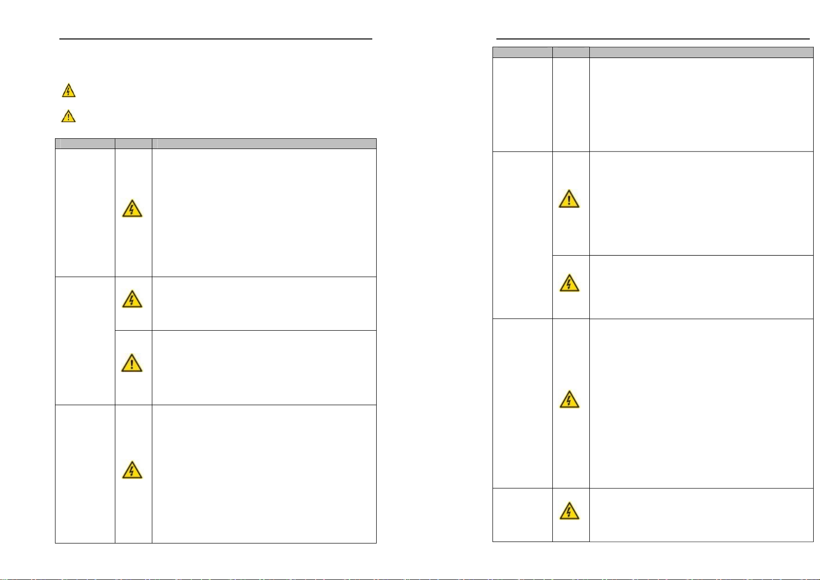
1-2.Safety precautions
Safety precautions in this manual are divided into the following two categories:
Danger: the dangers caused by failure to perform required operation, may result in
serious body injury or even death;
Caution:the dangers caused by failure to perform required operation,may
result in moderate injury or minor injury, and equipment damage;
Process Type Explanation
Before
installation Danger
★When unpacking, if control system with water, parts
missed or component damaged are found, do not install!
★If packing list does not match the real name, do not
install!
★Gently carry with care,otherwise there is the risk of
damage to equipment!
★Please do not use the damaged driver or the frequency
inverter with missed pieces,otherwise there is the risk of
injury!
★Do not use your hand to touch the control system
components, otherwise there is the risk of electrostatic
damage!
Danger
★Please install the unit on the metal or flame retardant
objects; away from combustible material. Failure to do so
may cause a fire!
★Never twist the mounting bolts of the equipment
components, especially the bolt with the red mark!
When
installing
Note
★Do not let the lead wires or screws fall into the driver.
Otherwise which may cause damage to the driver!
★Keep the driver installed in the place where less
vibration, avoid direct sunlight.
★When two or more converters are installed in a cabinet,
please pay attention to the installation location, ensure the
good heat dissipation effect.
When wiring
Danger
★Must comply with this manual's guidance,any
construction shall be performed by a professional
electrician, otherwise there would be the unexpected risk !
★A circuit breaker must be set between the inverter and
the power supply to separate them, otherwise it may cause a
fire!
★Verify if power is a zero-energy status before wiring,
otherwise there is a risk of electric shock!
★The inverter shall be grounded correctly according to
standard specifications, otherwise there is a danger of
electrical shock!
★Never connect the input power to the inverter output
terminals (U, V, W) . Note that the mark of the terminals,
Chapter 1 Inspection and safety precautions
3
Process Type Explanation
do not incorrectly connect wires! Otherwise which may
cause damage to the driver!
★Ensure that the distribution line meets the regional safety
standards of EMC requirements. The diameter of used
wire shall refer to the recommendations of this manual.
Otherwise it may cause an accident!
★When connecting to braking resistor,the braking resistor
must be connected to position between terminals (P, RB) of
the inverter
Note
★Please confirm whether the input power voltage is same
as the inverter rated voltage; wiring positions of power
input terminals (R,S,T) and output terminals (U,V,W) are
correct or not; and note that if there is a short circuit in the
peripheral circuit connected to driver,if the connected
lines are tight, otherwise it may cause damage to the
driver!
★Do not need to perform withstand voltage test for any
part of the inverter,this product has been tested before
leaving factory. Otherwise it may cause an accident!
Before
energizing
Danger
★The inverter's cover plate must close before power on.
Otherwise it may cause an electric shock!
★Wiring of all external accessories must comply with the
guidance of this manual,please correctly wiring in
accordance with the circuit connection methods described
in this manual. Otherwise it may cause an accident!
After
energizing Danger
★Do not open cover plate after energizing. Otherwise
there is a risk of electric shock!
★Do not touch the driver and peripheral circuits with wet
hands. Otherwise there is a risk of electric shock!
★Do not touch any input and output terminals of the
inverter. Otherwise there is a risk of electric shock!
★The inverter automatically perform the safety testing for
the external strong electrical circuit in the early stages of
energizing, therefore never touch the driver terminals (U,
V, W) or motor terminals, otherwise there is a risk of
electric shock!
★If you need to identify the parameters, please pay
attention to the danger of injury during motor rotation.
Otherwise it may cause an accident!
★Please do not change the inverter manufacturer
parameters. Otherwise it may cause damage to this unit!
During
operation Danger
★Do not touch the cooling fan and the discharge resistor
to feel the temperature. Otherwise it may cause burns!
★Non-professional personnel is not allowed to detect
signal when operating. Doing so may cause personal
injury or damage to this unit!
Chapter 1 Inspection and safety precautions
4
Process Type Explanation
Note
★When the inverter is operating, you should avoid that
objects fall into this unit.Otherwise cause damage to this unit!
★Do not start/stop the driver by switching on/off
contactor. Otherwise cause damage to this unit!
When
maintaining Danger
★Do not perform repairs and maintenance for the live
electrical equipment. Otherwise there is a risk of electric
shock!
★The repairs and maintenance task can be performed only
when the inverter voltage is lower than AC36V,generally
that is two minutes after powering off. Otherwise, the
residual charge from capacitor would cause personal
injury!
★Non-well-trained professional personnel is not allowed
to perform repairs and maintenance of inverter. Doing so
may cause personal injury or damage to this unit!
★After replacing the inverter,parameter settings must be
redone, all pluggable plugs can be operated only in the
case of powering off!
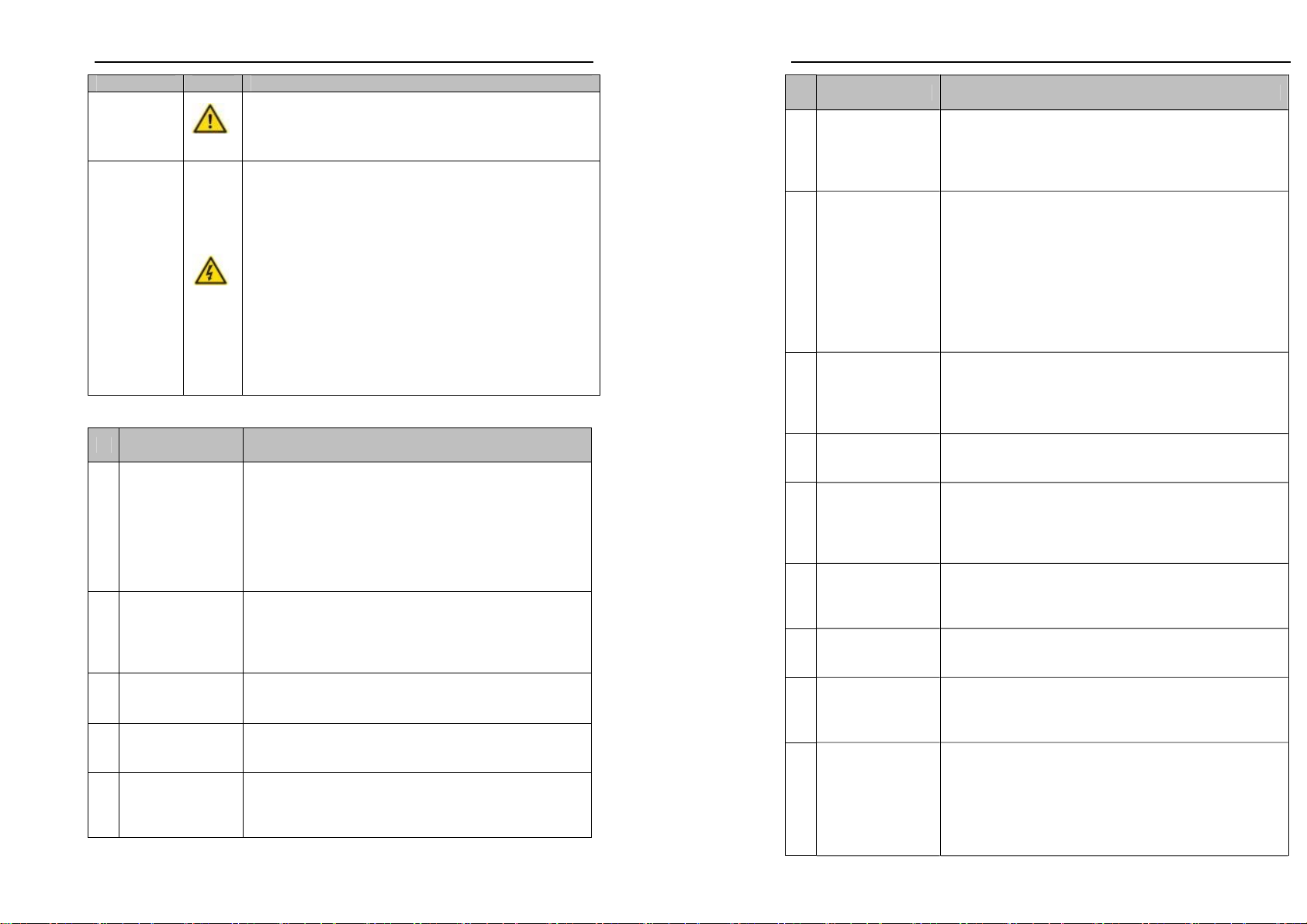
1-3.Precautions
No. Type Explanation
1 Motor insulation
inspection
Please perform motor insulation inspection for the first
time use, re-use after leaving unused for a long time as
well as regular check, in order to prevent damage to the
inverter because of the motor's winding insulation failure.
Wiring between motor and inverter shall be disconnected,
it is recommended that the 500V voltage type megger
should be adopted and insulation resistance shall be not
less than 5MΩ.
2 Motor thermal
protection
If the rated capacity of the selected motor does not match
the inverter, especially when the inverter rated power is
greater than the motor rated power,be sure to adjust the
motor protection parameter values inside inverter or install
thermal relay in the front of motor for motor protection.
3 Run over power
frequency
This inverter can provide (0Hz to 400Hz)output
frequency If the user is required to run at 50Hz or more,
please consider the endurance of your mechanical devices.
4 Vibrations of
mechanical device
Inverter output frequency may be encountered mechanical
resonance point of the load device, you can set jump
frequency parameter inside inverter to avoid the case.
5 Motor heat and
noise
The inverter output voltage is PWM wave that contains a
certain amount of harmonics, so the temperature rise,noise
and vibration of motor show a slight higher than frequency
power frequency operation.
Chapter 1 Inspection and safety precautions
5
No. Type Explanation
6
Output side with
piezoresistor or
capacitor for
improving power
factor
The inverter output is PWM wave, if the piezoresistor for
lightning protection or the capacitor for improving power
factor is installed in the output side, which easily cause the
inverter instantaneous overcurrent or even cause damage
to the inverter. Please do not use.
7
Contactor or
switch used in the
inverter
input/output
terminals
If contactor is installed between power supply and
inverter,the contactor is not allowed to start/stop the
inverter. Necessarily need to use the contactor to control
the inverter start/stop, the interval should not be less than
one hour. Frequent charging and discharging may reduce
the service life of the inverter capacitor. If the contactor or
switch is equipped between output terminals and motor,
the inverter should be turned on/off without output status,
otherwise which easily lead to damage to the inverter
module.
8 Use other than the
rated voltage
CA Series inverter is not suitable for use beyond the
allowable operating voltage described in this
manual,which easily cause damage to the parts inside
inverter. If necessary, please use the corresponding
transformer to change voltage.
9
Never change 3-
phase input to 2-
phase input
Never change CA Series 3-phase inverter to 2-phase one
for application. Otherwise it will lead to malfunction or
damage to the inverter.
10 Lightning surge
protection
The series inverter is equipped with lightning overcurrent
protection device, so it has the ability of self-protection to
lightning induction. For the area where lightning is
frequent, user should also install the extra protection in the
front of the inverter.
11
High altitude and
derating
application
When the inverter is used in areas over 1000m altitude,it is
required to reduce frequency because the thin air will
decrease the cooling effect of inverter. Please consult our
technician for details on the application.
12 Special use
If the user need to use methods other than the suggested
wiring diagram provided in this manual, such as common
DC bus, please consult our technician.
13
Precautions for
scrap disposal of
the inverter
It may explode when electrolytic capacitors on the main
circuit and printed circuit board are burned. When burning
plastic parts, it may produce toxic gases.Please disposing as
industrial waste.
14 About
adaptive motor
1) Standard adaptive motor shall be four-pole
asynchronous squirrel-cage induction motor. Apart
from the said motors, please select the inverter
according to the motor rated current.
2) The cooling fan and the rotor shaft for non-inverter
motor are coaxially connected, the fan cooling effect is
reduced when the rotational speed is reduced, therefore,

Chapter 1 Inspection and safety precautions
6
No. Type Explanation
when the motor works in overheating occasions,a strong
exhaust fan should be retrofitted or replace non-inverter
motor with the inverter motor;
3) The inverter has built-in the adaptive motor standard
parameters, according to the actual situation, please
identify motor parameters or accordingly modify the
default values to try to meet the actual value,otherwise it
will operation affect and protection performance;
4) When short-circuit of cable or motor internal will
activate the inverter alarm, even bombing. Therefore,
firstly perform insulation short-circuit test for the initial
installation of the motor and cable, routine maintenance
often also need to perform such test. Note that the parts
to be tested and the inverter shall be disconnected
completely when testing.
15 Others
1) Never connect the AC power to the inverter output
terminals (U, V, W) .
2) Properly fix and lock the panel before powering on, so
as to avoid hurting the personal safety due to internal
poor capacitors.
3) Never perform wiring, checking and other operations
after power is turned on.
4) Do not touch the internal circuit board and its
components in order to avoid the risk of electric shock
after this unit is powered,
5) Do not touch internal circuit board and any parts after
powering off and within five minutes after keyboard
indicator lamp goes out,you must use the instrument to
confirm that internal capacitor has been discharged
fully,otherwise there is a danger of electric shock.
6) Body static electricity will seriously damage the internal
MOS field-effect transistors, etc.,if there are not anti-
static measures, do not touch the printed circuit board
and IGBT internal device with hand, otherwise it may
cause a malfunction.
7) The ground terminal of the inverter (E or )shall be
earthed firmly according to the provisions of the
National Electrical Safety and other relevant standards.
Do not shut down (power off) by pulling switch,and
only cut off the power until the motor stopping
operation.
8) It is required to add the optional input filter attachment
so as to meet CE standards
Chapter 1 Inspection and safety precautions
7
1-4.Scope of applications
※ This inverter only applies to typical industrial three-phase AC asynchronous motor.
※ This inverter can only be used in those occasions recognized by this company, an
unapproved use may result in fire, electric shock, explosion and other accidents.
※ If the inverter is used in such equipments (e.g: equipments for lifting
persons,aviation systems, safety equipment, etc.) and its malfunction may result in
personal injury or even death. In this case,please consult the manufacturer for your
application.
Only the well-trained personnel can be allowed to operate this unit,
please carefully read the instructions on safety, installation, operation and
maintenance before use. The safe operation of this unit depends on proper
transport, installation, operation and maintenance!

8
Chapter 2 Standard specifications
2-1.Technical specifications
Inverter model Rated output
Power KW)
Rated input
Current(A)
Rated output
current (A)
Adaptive motor
Power (KW)
Single phase 220V ±10%
CA-203A 0.4 5.4 2.5 0.4
CA-204A 0.75 8.2 4.0 0.75
CA-207A 1.5 14.0 7.0 1.5
CA-210A 2.2 23 10 2.2
Three-phase 220V ±10%
CA-203S 0.4 4.1 2.5 0.4
CA-204S 0.75 5.3 4.0 0.75
CA-207S 1.5 8.0 7.0 1.5
Three-phase 380V ±10%
CA-401S 0.4 2.0 1.2 0.4
CA-403S 0.75 4.3 2.5 0.75
CA-404S 1.5 5.0 3.8 1.5
CA-405S 2.2 5.8 5.1 2.2
CA-409S 3.7 10 8.5 3.7
Note: the 220V voltage level can be used as a brake unit selection; 380V voltage
brake unit as the standard, can not do for selection.
Chapter 2 Standard specifications
9
2-2.Technical specifications
Items Specifications
Voltage and frequency
levels
Single phase 220V, 50/60Hz
Three-phase 220V, 50/60Hz
Three-phase 380V,50/60Hz
Power
Allowable fluctuation
Voltage: ± 10% ;Frequency: ± 5%
The voltage unbalance rate is less than 3% and the
distortion rate meets the IEC61800-2 standard.
Control system High performance vector control inverter based on
DSP
Output frequency 0.00 to 400.0Hz
Control method V/F control
Open-loop flux vector control
Automatic torque
boost function
Realize low frequency (1Hz) and large output
torque control under the V/F control mode.
Frequency setting
resolution
Digital: 0.01Hz
Analog: highest frequency × 0.2%
V/F curve mode Linear,square root/m-th power,custom V/F curve
Over load capability Rated Current 150% - 60 seconds, Rated Current
200% - 1 seconds
Slip compensation Slip compensation available
Carrier Frequency 1kHz to 15kHz
Start torque 0.5Hz/150% (Open-loop flux vector control)
Speed range 1:100 (Open-loop flux vector control)
Steady-speed precision
(Speed control accuracy)
Open-loop flux vector control: ≤± 0.5% (rated
synchronous speed)
Torque response ≤40ms (Open-loop flux vector control)
Torque boost Automatic torque boost; manual torque boost (0.1%
to 30.0%)
Linear ac/deceleration
Linear acceleration and deceleration mode; two
kinds of acceleration and deceleration time; time
range 0.1s to 3600.0s.
DC braking
DC braking frequency: 0.00Hz to max.output
frequency;
Braking time: 0.0 to 50.0 seconds
Braking current value: 0.0% to 150.0%
Jogging control
Jog Frequency Range: 0.00Hz to max.output
frequency;
Jog Ac/deceleration time: 0.1s to 3600.0s
Multi-speed operation Achieve up to 16-speed operation through the
control terminal
Control system
Built-in PID Easy to realize closed-loop control system for the
process control.

Chapter 2 Standard specifications
10
Items Specifications
Automatic voltage
regulation (AVR)
Automatically maintain a constant output voltage
when the voltage of electricity grid changes
Running method Keyboard/terminal/communication
Frequency
setting
Total 8 frequency stetting modes: digital,analog
voltage/current, multi-speed and serial port.
Start signal Forward run
Reverse run
Multi-speed At most 16-speed can be set (run by using the
multi-function terminals )
Multi-stage
acceleration
At most 2-stage acceleration can be set (run by
using the multi-function terminals)
Emergency stop Interrupt controller output
Wobbulate run Process control run
Jog running Slow speed running
Fault reset When the protection function is active, you can
automatically or manually reset the fault condition.
Input signal
PID feedback
signal Including DC 0 to 10V/0 to 20mA
Running status Motor status display, forward, reverse, program
running status.
Fault output Relay contact capacity AC 250V/7A
Analog output
1-way analog output, 9 signals can be selected such
as frequency,current,voltage and other, output
signal range (DC 0 to 10V/0 to 20mA) .
Output signal
Output signal 2-way output,there are 8 signals each way
Run function
Limit frequency,jump frequency,slip
compensation,reversal protection, auto-tuning, PID
control
DC current braking
Built-in PID regulates braking current to ensure
sufficient braking torque under no overcurrent
condition.
Running command
channel
Three channels: operation panel,control terminals
and serial communication port. They can be
switched through a variety of ways.
Frequency source
Total 8 frequency sources: digital,analog
voltage,analog current, multi-speed and serial port.
They can be switched through a variety of ways.
Input terminals 5 digital input terminals, compatible with the active
PNP or NPN input. 2 Analog input terminals
Running
Output terminals
One digital output terminals (bipolar output) ; one
relay output terminal; 2 analog output terminals
respectively for optional range (0 to 20mA or 0 to
10V),they can be used to set frequency, output
Chapter 2 Standard specifications
11
Items Specifications
frequency, speed and other physical parameters.
Support 0.1-10kHz square signal output.
Inverter protection
Overvoltage protection, undervoltage protection,
overcurrent protection, overload protection,
overheat protection, overcurrent stall protection,
overvoltage stall protection, external fault,
communication error, PID feedback signal
abnormalities.
IGBT temperature
display Displays current temperature IGBT
Instantaneous power-
down restart
Less than 15 milliseconds: continuous operation.
More than 15 milliseconds: automatic detection of
motor speed, instantaneous power-down restart.
Speed start tracking
method
The inverter automatically tracks motor speed after
it starts
Protection function
Parameter protection
function
Protect inverter parameters by setting administrator
password and decoding
Running
message
Monitoring objects including: running frequency,
set frequency, output current, DC bus voltage,
output voltage, actual motor speed, PID setting
value, PID feedback value, input terminal status,
output terminal status, analog AI1 value, analog
AI2 value,current stage of multi-speed, torque set
value, etc.
LED
Keyboard
Error
message
At most save 3 error messages,and the
time,type,voltage,current,frequency and terminal
status can be queried when the failure is occurred.
LED display Display parameters
Display
Key lock It can lock all keys in order to prevent misuse.
Communica
-tion
RS485 Completely isolated RS485 communication module
can communicate with the host computer.
Environment
temperature
-10 ℃to 40 ℃(temperature at 40 ℃to 50 ℃,
please derating for use)
Storage temperature -20 ℃to 65 ℃
Environment humidity Less than 90% RH, non-condensing water droplets
Height and vibration Below 1000m, below 5.9m/s² (= 0.6g)
Environment
Application sites
Indoor where no sunlight or corrosive, explosive
gas and water vapor, dust, flammable gas, oil mist,
water vapor, drip or salt, etc.

Chapter 2 Standard specifications
12
Items Specifications
Altitude Below 1000m
Pollution degree 2
Product adopts safety
standards. IEC61800-5-1:2007
Product
Standard
Product adopts EMC
standards. IEC61800-3:2005
Cooling method Forced air cooling
13
Chapter 3 Keyboard
3-1.Keyboard description
Keyboard is used to operate CA SERIES frequency inverters, read status data and
adjust parameters.
Keyboard Schematic Diagram
3-2.Keyboard indicators
Indicator flag Name Meaning
FWD Forward running lamp ON means that the inverter is forward operating.
REV Reverse running lamp ON means that the inverter is reverse operating.
Hz Frequency Indicator Frequency unit of the inverter
Status Indicator
A Current Indicator Current unit of the inverter
Correspondence that LED displays symbols and characters/digits is as follows:
Display
letters
Corresponding
letters
Display
letters
Corresponding
letters
Display
letters
Corresponding
letters
0 1 2
3 4 5
6 7 8
9 A B
Digital
display
area
C d E
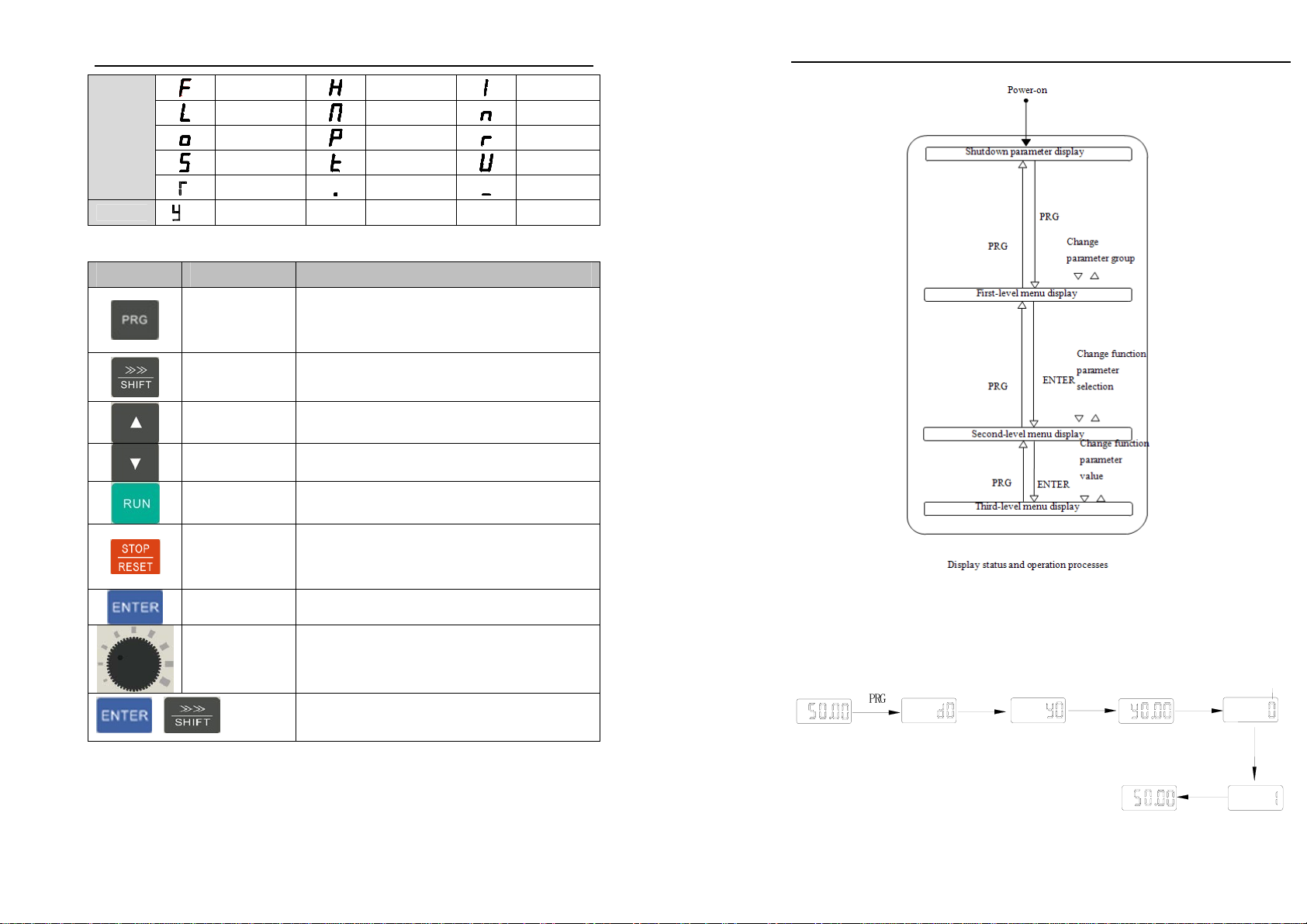
Chapter 3 Keyboard
14
F H I
L N n
o P r
S t U
T . -
y
3-3.Description of operation panel keys
Sign Name Function
Parameter
Setting/Exit Key
* Enter top menu parameter change status
* Exit from function option change
* Return to status display menu from sub-menu or
function option menu
Shift Key
* Select circularly parameters under run or stop
interface; select parameters when modifying the
parameters.
Ascending Key * Data or function code ascending
Decending Key * Data or function code decending
Run Key Used for running operation in the keyboard mode.
Stop/Reset Key
* Press the key to stop running in running status;
press the key to reset in fault alarm status, can be
used to reset the operation, the key is subject to
function code F6.00.
Enter Key * Enter into levels of menu screen,confirm
settings.
Keyboard
potentiometer
* F0.02 is set to 3,keyboard potentiometer is used
to set the running frequency.
+
Simultaneously press two keys to lock or unlock
the keypad.
3-4.Examples of parameter settings
Instructions on viewing and modifying function code
CA SERIES inverter operation panel has three levels of menu structure for
parameter settings and other operations. Three levels of menu is as follows: function
parameter group (first level menu) →function code (second level menu) →function
code settings (third level menu) . The operation flow is shown in the figure.
Chapter 3 Keyboard
15
Description: return to the second-level menu from the third-level menu by pressing
PRG key or ENTER key. The difference between the two keys : press ENTER to return
the second-level menu and save parameters setting before returning, and automatically
transfer to the next function code; press PRG to return directly to the second-level menu,
do not save parameters setting,and return to current function code .
Example 1 :restore factory default
P
R
G▲ENTER ENTER Flicker
▲
ENTER
Example 2 :change function code F0.01 from 50.00Hz to 40.00Hz

Chapter 3 Keyboard
16
▲ENTER
Fl i cker
Fl i cker
Flicker
ENTER
PRG
PRG
PRG
ENTER
Fl i cker
SHIFT
▲
▲
In the third-level menu status, if the parameter has not blinking bit, it means that
the function code can not be modified, the possible causes include:
1) The function code can not be used to modify the parameters. Such as actual
detection parameters, run record parameters.
2) The function code can not be modified in the running status,can be modified only
after this unit is stopped.
How to view status parameters
In stop or run status, operate SHIFT key to display a variety of status parameters
respectively. Parameter display selection depends on function code F6.01 (run
parameter) and F6.02 (stop parameter) .
In stop status, there are 10 run status, you can set to display or not display them: set
frequency, bus voltage, DI input status, DO output status, PID settings and PID
feedback, analog input AI1 voltage, analog input AI2 voltage,and switch and display the
selected parameter by pressing key orderly.
In run status, there are 16 run status, you can set to display or not display them:
running frequency, set frequency, bus voltage, output voltage, output current, output
power, output torque, DI input status, DO output status, analog input AI1 voltage,
analog input AI2 voltage, linear speed, PID settings and PID feedback,etc, their display
depends on function code F6.01, and switch and display the selected parameter by
pressing key orderly.
Inverter powers off and then powers on again, the displayed parameters are the
selected parameters before power-off.
3-4-1.Password settings
The inverter has password protection, when Y0.01 is non-zero value, that is user
password, password protection will enter into force when you exit from function code
editing status, press the PRG key again,it will display "-----", you must enter correct
user password before entering regular menus, otherwise inaccessible.
To cancel the password protection function, firstly enter correct password to access
and then set Y0.01 to 0.
3-4-2.Motor parameter auto tunning
Select the operating mode of vector control, you must accurately input parameters
Chapter 3 Keyboard
17
of the motor's nameplate before inverter operation, CA SERIES frequency inverter will
match the standard motor parameters according to the nameplate parameters; the vector
control method is highly dependent on motor parameters, in order to get good control
performance, the accurate parameters of the controlled motor must be required
Motor parameter auto tunning steps are as follows (Take asynchronous motor as an
example) :
Firstly select command source as keyboard control (F0.04=0). then input the
following parameters according to the actual motor parameters (selection is based on the
current motor) :
Motor Selection Parameters
Motor
b0.00: motor type selection b0.01: motor rated power
b0.02: motor rated voltage b0.03: motor rated current
b0.04: motor rated frequency b0.05: motor rated speed
If the motor can NOT completely disengage its load, please select 1 (asynchronous
motor parameter static auto tunning) for b0.11, and then press the RUN key on the
keyboard panel, the inverter will automatically calculate the motor’s following
parameters:
If the motor can completely disengage its load, please select 2 (asynchronous
motor parameter comprehensive auto tunning) for b0.11, and then press the RUN key on
the keyboard panel:
Motor Selection Parameters
Motor
b0.06: Asynchronous motor stator resistance
b0.07: Asynchronous motor rotor resistance
b0.08: Asynchronous motor stator and rotor inductance
b0.09: Asynchronous motor stator and rotor mutual inductance
b0.10: Asynchronous motor no-load current
Complete motor parameter auto tunning
18
Chapter 4 Installation and commissioning
4-1.Operating environment
(1) ambient temperature -10 ~ 50. After more than 40 degrees Celsius, in
accordance with the proportion of 1 to 3% degrees down the amount of.
Inverter is not recommended in the environment above 50.
(2) to prevent electromagnetic interference, away from the source of interference.
(3) to prevent the invasion of water, steam, dust, dust, cotton, metal powder.
(4) to prevent oil, salt and corrosive gas intrusion.
(5) avoid shaking. Maximum amplitude is not more than 5.9m/s (0.6g).
(6) to avoid high temperature and humidity and no rain water poured, relative
humidity is less than 90%RH, does not allow the dew. In the presence of corrosive
gases in the space, the maximum relative humidity can not exceed 60%.
(7) altitude.
(8) the prohibition of the use of flammable, combustible, explosive gas, liquid or
solid hazardous environment.
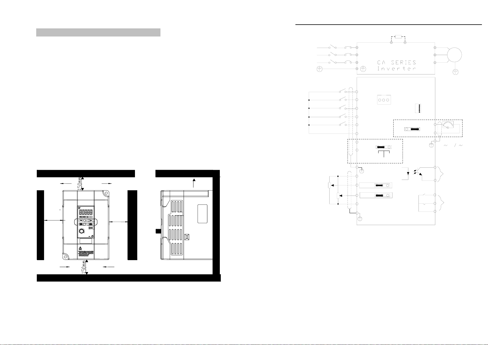
4-2.Installation direction and space
The inverter shall be installed in the room where it is well ventilated, the wall-
mounted installation shall be adopted, and the inverter must keep enough space around
adjacent items or baffle (wall) . As shown below figure:
4-3.Wiring diagram
The wiring of inverter is divided into two parts of main circuit and control circuit.
User must correctly connect in accordance with the wiring circuit as shown in the
following figure.
or more
or more or more
Air inAir in
Air out
Air
Air out
or more
50mm 50mm
Chapter 4 Installation and commissioning
19
123
VI
VR
1K
2W
+10V
AI1
GND
AI2
VI
TA
TB
TC
Relay
output
MO1
MCM Signal output
JP6
Analog output
AO1
GND
123
V
I
010V 0 20mA
JP2
JP3
DI1
DI2
DI3
DI4
DI5
DI1 input terminals
DI2 input terminals
COM
PLC
+24V
123JP1
+24V COM
PLC
JP4
Control circuit
M3~
PRB
Main
circuit
R
S
T
U
V
W
R
S
T
Circuit
breaker Contactor
Braking resistor (optional)
485Communication
port
CN3
DI3 input terminals
DI4 input terminals
DI5 input terminals
485Communication
port
Note: the V6 version of the control board and the above 485 communication ports
are CN3, V6 and JP6 port.
Chapter 4 Installation and commissioning
20
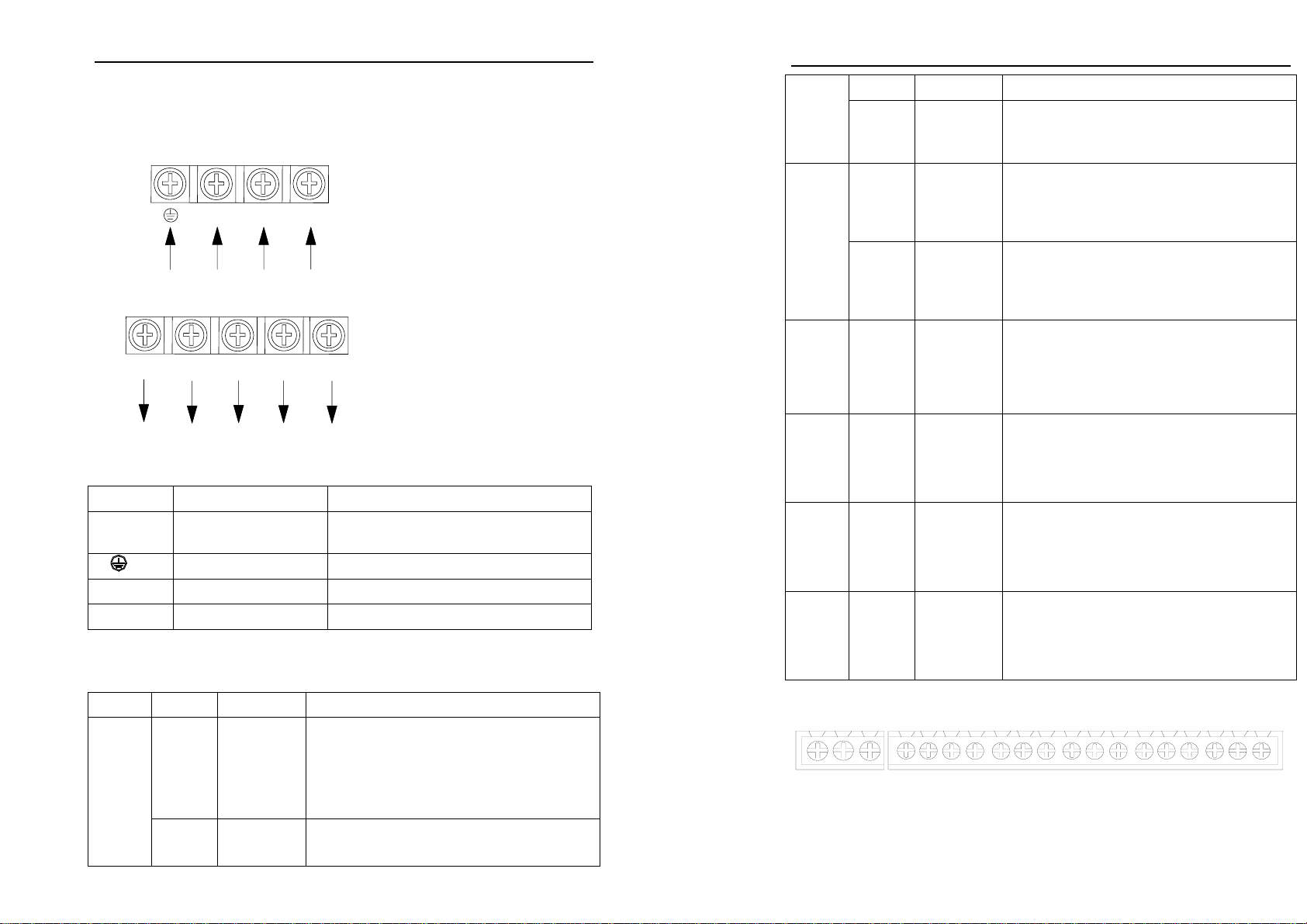
4-4.Main circuit terminal
4-4-1. CA SERIES main circuit terminal
Inverter output
terminals
Braking resistor
terminals
PRB
RST
Main power input
terminals
Ground
terminals
UVW
4-4-2.Function Description of Terminals
Terminals Name Description
R, S, T Inverter input terminals Connection point of AC input power
supply, single-phase connects to S, T
Ground terminals Ground terminals
P、RB Braking resistor terminals Connect to braking resistor
U、V、W Inverter output terminals Connect to three-phase motor
4-5.Control circuit terminals
4-5-1. Description of control circuit terminals
Category Symbol Name Function
+10V、
GND
External
+10 Power
Output +10V power supply, maximum output
current: 10mA
Generally it is used as power supply of external
potentiometer, potentiometer resistance range:
1kΩto 5kΩ.
Power supply
+24V、
COM
External+24
V power
Output +24V power supply, generally it is used
as power supply of digital input and output
terminals and external sensor.
Chapter 4 Installation and commissioning
21
supply Maximum output current: 200mA
PLC
External
power input
terminal
When external signal is used to drive, please
unplug JP1 jumpers,PLC must be connected to
external power supply. Factory default and +24V
connection.
AI1、
GND
Analog
input
terminal 1
1.Input range: (DC 0V to 10V/0 to 20mA),
depends on the selected JP2 jumper on control
panel.
2.Input impedance: 25.5kΩwith voltage input,
500Ωwith current input.
Analog input
AI2,
GND
Analog
input
terminal 2
1.Input range: (DC 0V to 10V/0 to 20mA),
depends on the selected JP3 jumper on control
panel.
2.Input impedance: 25.5kΩwith voltage input,
500Ωwith current input.
Digital input
DI1 TO
DI5
Multifunctio
n digital
terminals (1
to 5)
1. Opto-coupler isolation, compatible with
bipolar input
2. Input impedance: 3.3 kΩ
3. Voltage range of level input : 9V to 30V,
depends on the selection of JP1 jumper on the
control panel.
Analog
output
AO1,
GND
Analog
output
terminals 1
The selected JP4 jumper on control panel
determines voltage or current output. Output
voltage range: 0V to 10V, output current range:
0mA to 20mA
Digital
output
MO1,
MCM
Output
signal 1
Output Open Collector signal MO1, the common
terminal is MCM.
Output voltage range: 0 to 24V, output current
range: 0 to 50mA
Relay
output
TA/TB/TC Output
signal 2
Relay output, TA normally open, TB normally
closed, TC common terminal, output function is
determined by F2.03 setting. Contact capacity:
7A/AC250V
4-5-2.Arrangement of control circuit terminals
1. CA SERIESMCB board control circuit terminal
TA TC TB DI 1 DI 2 DI 3 DI 4 DI 5 PLC24V COM COM 10V AI 1 AI 2 AO1 GND MCM MO1
4-6.Wiring precautions:
※ The U, V, W output end of inverter can not install phase advancing capacitor or RC
absorbing device. The inverter input power must be cut off when replacing the
Chapter 4 Installation and commissioning
22
motor
※ Do not let metal chips or wire ends into inside the inverter when wiring,otherwise
which may cause malfunction to the inverter.
※ Disconnect motor or switch power-frequency power supply only when the inverter
stops output
※ In order to minimize the effects of electromagnetic interference,it is recommended
that a surge absorption device shall be installed additionally when electromagnetic
contactor and relay is closer from the inverter.
※ External control lines of inverter shall adopt isolation device or shielded wire.
※ In addition to shielding, the wiring of input command signal should also be aligned
separately, it is best to stay away from the main circuit wiring.
※ If the carrier frequency is less than 3KHz, the maximum distance between the
inverter and the motor should be within 50 meters; if the carrier frequency is
greater than 4KHz, the distance should be reduced appropriately, it is best to lay
the wiring inside metal tube.
※ When the inverter is additionally equipped with peripherals (filter, reactor, etc.),
firstly measure its insulation resistance to ground by using 1000 volt megger, so as
to ensure the measured value is no less than 4 megohms.
※ When the inverter need to be started frequently, do not directly turn power off, only
the control terminal or keyboard or RS485 operation command can be used to
control the start/stop operation, in order to avoid damage to the rectifier bridge.
※ Do not connect the AC input power to the inverter output terminals (U, V, W) .
※ To prevent the occurrence of an accident,the ground terminal ( ) must be earthed
firmly (grounding impedance should be less than 10 ohms), otherwise the leakage
current will occur.
※ The specifications on wires used by the main circuit wiring shall comply with the
relevant provisions of the National Electrical Code.
※ The motor's capacity should be equal to or less than the inverter's capacity.
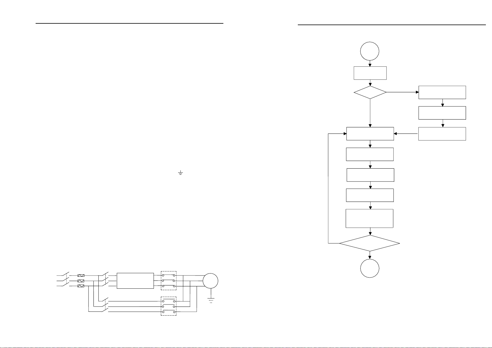
4-7.Spare circuit
When the inverter occurs the fault or trip, which will cause a larger loss of
downtime or other unexpected faults. In order to avoid this case from happening, please
additionally install spare circuit to ensure safety.
Note: the characteristics of spare circuit must be confirmed and tested
beforehand,and its power-frequency shall be in accordance with the phase sequence of
the inverter.
inverter
R
S
T
K1 K2
K3 Interlocked AC contactor
of MCC1 and MCC2
M
3~
MCC1
MCC2
CA SERIES
Chapter 4 Installation and commissioning
23
4-8.Commissioning
Commission-
ing
Select control manner
(setting F0.00)
F0.00=?
Configure correctly motor
parameters b0.01 to b0.05
group
Select appropriate
ac/deceleration time(setting
F0.05, F0.06)
Motor parameter auto
tunning fault(setting
b0.11)
Open-loop flux
vector control
V/F
0
2
Select run command
channel(setting F0.04)
Select appropriate frequency
command(setting F0.02)
Select motor start-up
mode(setting F3.00)
Start motor to run, observe
the phenomenon, if
abnormal, please refer to the
troubleshooting.
End
Select appropriate
ac/deceleration time(setting
F0.05/F0.06)
control
NO
YES
Achieve the required
control effect?
● Firstly confirm that AC input power supply voltage shall be within inverter
rated input voltage range before connecting power supply to the inverter.
● Connect power supply to the R, S and T terminals of the inverter.
● Select the appropriate operation control method

24
Chapter 5 Function parameter
5-1.Menu grouping
CA SERIES inverter function parameters are grouped by function, there is d0
group, F0 group to Fb group, E0 group to E3 group, b0 group, y0 group to y1 group, L0
group, a total of 21 groups. Each functional group includes several functional code.
F group and E group are the basic function parameters, d group is monitoring
function parameters and b group is motor parameters.
In order to more effectively carry out parameter protection, the inverter provides a
password protection of function code. y0.01 is used to set parameters protection
password, you can enter into parameter menu only after inputing correct password
under function parameters mode. Password protection is canceled when y0.01 is set to
00000.
L0 group is factory function parameters, users do not have access to the group of
parameters.
Function parameter table "Change", change properties (ie, whether to allow the
change or not and change conditions) and symbol description is as follows:
"★": indicates that the parameter value can not be changed when the inverter is
running;
"●": indicates that the parameter value is the actual measured value, can not be
changed;
"☆": indicates that the parameter value can be changed when the inverter is
running or stoped;
“▲”: "Factory parameters", prohibit the user to operate;
"-": indicates that the parameter factory default is none or the value is undefined.
Code Parameter Group Name Functional Description
d0 Monitoring function group Monitoring frequency, current, etc
F0 Basic function group Frequency setting, control mode, acceleration and
deceleration time
F1 Input terminals group Analog and digital input functions
F2 Output terminals group Analog and digital output functions
F3 Start and stop control group Start and stop control parameters
F4 V/F control group V/F control parameters
F5 Vector control group Vector control parameters
F6 Keyboard and display group To set key and display function parameters
F7 Auxiliary function group To set Jog, jump frequency and other auxiliary
function parameters
Chapter 5 Function parameter
25
F8 Fault and protection group To set fault and protection parameters
F9 Communication parameter
group To set MODBUS communication function
FA Torque control group To set parameters under torque control mode
Fb Control optimization group To set parameters of optimizing the control
performance
E0 Wobbulate control group Wobbulate function parameters setting
E1 Multi-speed control group Multi-speed setting
E2 PID control group To set Built-in PID parameters
E3 Virtual DI, virtual DO group Virtual IO setting
b0 Motor parameters group To set motor parameter
y0 Function code management
group User password, initialization parameter setting
y1 Fault history search group Information on current, former or first two faults
5-1-1.d0 Group - Monitoring function
No. Code Parameter name Functional Description Smallest
unit Cha
nge
1. d0.00 Running frequency Inverter current actual output
frequency 0.01Hz ●
2. d0.01 Set frequency Inverter current actual setting
frequency 0.01Hz ●
3. d0.02 DC bus voltage Detected value for DC bus voltag
e
1V ●
4. d0.03 Inverter output voltag
e
Inverter actual output voltage 1V ●
5. d0.04 Inverter output current Inverter actual output current 0.1A ●
6. d0.05 Inverter output power Inverter actual output power 0.1kW ●
7. d0.06 Inverter output torque Inverter actual output torque
percentage 1% ●
8. d0.07 Input terminal status Input terminal status - ●
9. d0.08 Output terminal status Output terminal status - ●
10. d0.09 Analog AI1 value Analog AI1 input voltage value 0.01V ●
11. d0.10 Analog AI2 value Analog AI2 input voltage value 0.01V ●

Chapter 5 Function parameter
26
12. d0.11 Panel potentiometer
voltage
Panel potentiometer setting
voltage value 0.01V ●
13. d0.12 Motor actual speed Motor actual running speed 1rpm ●
14. d0.13 PID setting value Setting value percentage under
PID adjustment mode 1% ●
15. d0.14 PID feedback value Feedback value percentage under
PID adjustment mode 1% ●
16. d0.15 Current stage of
multi-speed Current stage of multi-speed - ●
17. d0.16 Reserved
18. d0.17 Inverter module
temperature 0 to 100.0℃0.1℃●
19. d0.18 Software version DSP software version number - ●
20. d0.19 Cumulative running
time of this unit 0 to 65535h 1h ●
21. d0.20 Torque setting value
Observe the set command torque
under speed mode or torque
control mode
0.1% ●
5-1-2.F0 Group - Basic function
No. Code Parameter
name Setting range Factory
default Change
22. F0.00 Control mode
0: Open-loop flux vector control
1: Reserved
2: V/F control
3: torque control
2 ★
23. F0.01 Keyboard set
frequency
0.00Hz to F0.08 (maximum output
frequency) 50.00Hz ☆
24. F0.02
Frequency
command
selection
0: keyboard setting
1: Analog AI1 setting
2: Analog AI2 setting
3: Panel potentiometer setting
4: AI1+ AI2 setting
5: Multi-speed operation setting
6: PID control setting
7: Remote communications setting
0 ★
25. F0.03
Keyboard and
terminal
UP/DOWN
setting
0: Valid, and the inverter power
failure with data storage
1: Valid, and the inverter power
failure without data storage
0 ☆
Chapter 5 Function parameter
27
2: UP/DOWN setting is invalid
3: Valid when running, invalid
when stop
26. F0.04 Command source
channel
0: Keyboard command channel
1: Terminal command channel
2: Communication command
channel
0 ★
27. F0.05 Acceleration
time 1 0.1 to 3600.0s
D
epends
on model
s
☆
28. F0.06 Deceleration
time 1 0.1 to 3600.0s
D
epends
on model
s
☆
29. F0.07 Carrier frequency
setting 1.0 to 15.0kHz
D
epends
on model
s
☆
30. F0.08 Maximum output
frequency 10.00 to 400.00Hz 50.00Hz ★
31. F0.09
Upper limit
frequency setting
source selection
0: Keyboard setting (F0.10)
1: Analog AI1 setting
2: Analog AI2 setting
3: Multi-speed setting
4: Remote communications setting
Note: Option 1 to 4, the setting
value 100% corresponds to the
maximum output frequency
0 ★
32. F0.10
Running
frequency upper
limit
F0.11 to F0.08 (maximum output
frequency) 50.00Hz ☆
33. F0.11
Running
frequency lower
limit
0.00Hz to F0.10 (running
frequency upper limit) 0.00Hz ☆
34. F0.12
Running
direction
selection
0: default
1: opposite
2: reverse prohibited
0 ★
35. F0.13 AVR function
selection
0: Invalid
1: full valid
2: only invalid during deceleration
1 ☆
5-1-3.F1 Group - Input terminals
No. Code Parameter name Setting range Factory
default Change
36. F1.00 DI1 terminal
function selection
0: No function
1: Forward run 1 ★

Chapter 5 Function parameter
28
37. F1.01 DI2 terminal
function selection 2 ★
38. F1.02 DI3 terminal
function selection 0 ★
39. F1.03 DI4 terminal
function selection 9 ★
40. F1.04 DI5 terminal
function selection 4 ★
41. F1.05 Reserved
2: Reverse run
3: Three-wire operation control
4: Forward Jog
5: Reverse Jog
6: Frequency setting increment
(UP)
7: Frequency setting decrement
(DOWN)
8: Free stop
9: Fault reset
10: External fault input
11: Frequency change settings
clear
12: Multi-speed terminal 1
13: Multi-speed terminal 2
14: Multi-speed terminal 3
15: Multi-speed terminal 4
16: Ac/deceleration time
selection
17: Control command switch
terminal
18: Ac/deceleration prohibited
19: PID control pause
20: Wobbulate pause (stops at
the current frequency)
21: Wobbulate reset (returns to
the center frequency)
22: Torque control prohibited
23: Frequency change settings
temporarily clear
24: Stop DC braking
25: Reserved
42. F1.06 Terminal control
operation mode
0: Two-wire type control 1
1: Two-wire type control 2
2: Three-wire type control 1
3: Three-wire type control 2
0 ★
43. F1.07
Change rate of
terminal UP/DOWN
frequency increment
0.01 to 50.00Hz/s 0.50Hz/s ☆
44. F1.08 AI1 lower limit 0.00V to F1.10 0.00V ☆
45. F1.09 AI1 lower limit
setting -100.0% to 100.0% 0.0% ☆
46. F1.10 AI1 upper limit F1.08 to 10.00V 10.00V ☆
47. F1.11 AI1 upper limit -100.0% to 100.0% 100.0% ☆
Chapter 5 Function parameter
29
setting
48. F1.12 Filter time of AI1
input 0.00s to 10.00s 0.10s ☆
49. F1.13 AI2 lower limit 0.00V to F1.15 0.00V ☆
50. F1.14 AI2 lower limit
setting -100.0% to 100.0% 0.0% ☆
51. F1.15 AI2 upper limit F1.13 to 10.00V 10.00V ☆
52. F1.16 AI2 upper limit
setting -100.0% to 100.0% 100.0% ☆
53. F1.17 Filter time of AI2
input 0.00s to 10.00s 0.10s ☆
54. F1.18 Times of switching
quantity filtering 1 to 10 5 ☆
55. F1.19 DI terminal mode
selection 0x000 to 0x1FF 000 ★
5-1-4.F2 Group - Output terminals
No. Code Parameter name Setting range Factory
default Change
56. F2.00 MO1 output selection 1 ☆
57. F2.01 Reserved
58. F2.02 Reserved
59. F2.03 Relay output selection
0: No output
1: Motor forward running
2: Motor reverse running
3: Fault output
4: Frequency level detection
FDT output
5: Frequency arrival
6: Zero speed running
7: Upper limit frequency
arrival
8: Lower limit frequency
arrival
9 to 10: Reserved
1 ☆
60. F2.04 AO1 output selection
0: Running frequency
1: Set frequency
2: Output current
3: Output torque
4: Output power
5: Output voltage
6: Analog input AI1 value
7: Analog input AI2 value
8: Run speed
0 ☆

Chapter 5 Function parameter
30
9 to 10: Reserved
61. F2.05 AO1 output lower limit 0.0% to F2.07 0.0% ☆
62. F2.06
Lower limit
corresponds to AO1
output
0.00V to 10.00V 0.00V ☆
63. F2.07 AO1 output upper limit F2.05 to 100.0% 100.0% ☆
64. F2.08 Upper limit correspond
s
to AO1 output 0.00V to 10.00V 10.00V ☆
65. F2.09 MO1 Turn-on delay
time
0.0~3600s 0.0s ☆
66. F2.10 MO1 Turn-off delay
time
0.0~3600s 0.0 s ☆
67. F2.11 Turn-on delay time of
relay
0.0~3600s 0.0 s ☆
68. F2.12 Turn-off delay time of
relay
0.0~3600s 0.0 s ☆
69. F2.13 Reserved
70. F2.14 D0 terminal active
status selection 0x00 to 0x1F 00 ☆
71. F2.15 MO1 output type
selection
0: pulse output
1: digital output ☆
72. F2.16 MO1 pulse output
selection
0:running frequency
1: set frequency
2: output current
3: output torque
4: output power
5: output voltage
6: AI1 input value
7: AI2 input value
8:running speed/RPM
9~10: reserved
☆
73. F2.17 MO1 lower limit of
output pulse 0.0%~F2.19 0.0% ☆
74. F2.18
Lower limit
corresponding M01
pulse output
0.1-10kHz 0.0kHz ☆
75. F2.19 Higher limit of M01
pulse output F2.17-100% 100% ☆
Chapter 5 Function parameter
31
76. F2.20
Higher limit
corresponding M01
pulse output
0.1-10kHz 10kHz ☆
5-1-5.F3 Group - Start and stop control
No. Code Parameter name Setting range Factory
default Change
77. F3.00 Start running mode
0: Directly startup
1: Speed tracking restart
2: First DC braking and then
start
0 ★
78. F3.01 Startup start frequency 0.00 to 10.00Hz 0.00Hz ☆
79. F3.02 Hold time for start
frequency 0.0 to 50.0s 0.0 s ★
80. F3.03 Braking current before
start 0.0 to 150.0% 0.0% ★
81. F3.04 Braking time before start 0.0 to 50.0s 0.0 s ★
82. F3.05 Stop mode selection 0: Deceleration stop
1: Free stop 0 ☆
83. F3.06 Start frequency of stop
braking
0.00 to F0.08 (maximum
output frequency) 0.00Hz ☆
84. F3.07 Waiting time of stop
braking 0.0 to 50.0s 0.0 s ☆
85. F3.08 Stop DC braking current 0.0 to 150.0% 0.0% ☆
86. F3.09 Stop DC braking time 0.0 to 50.0s 0.0 s ☆
5-1-6.F4 Group - V/F control
No. Code Parameter name Setting range Factory
default Change
87. F4.00 V/F curve setting
0: linear V/F curve
1: multi-point V/F curve
2: square V/F curve
3:1.25th power V/F curve
4:1.75th power V/F curve
0 ★
88. F4.01 Torque boost 0.0%: automatic torque boost
0.1% to 30.0% 0.0% ☆
89. F4.02 Torque boost cut-off 0.0% to 50.0% (relative to
rated frequency of motor) 20.0% ★

Chapter 5 Function parameter
32
90. F4.03 V/F frequency point 1 0.00Hz to F4.05 0.00Hz ★
91. F4.04 V/F voltage point 1 0.0% to 100.0% 0.0% ★
92. F4.05 V/F frequency point 2 F4.03 to F4.07 0.00Hz ★
93. F4.06 V/F voltage point 2 0.0% to 100.0% 0.0% ★
94. F4.07 V/F frequency point 3 F4.05 to b0.04 (rated motor
frequency) 0.00Hz ★
95. F4.08 V/F voltage point 3 0.0% to 100.0% 0.0% ★
96. F4.09 V/F slip compensation
limit 0.0 to 200.0% 0.0% ☆
5-1-7.F5 Group - Vector control group
No. Code Parameter name Setting range Factory
default Change
97. F5.00 Speed loop proportional gain 1 0 to 100 20 ☆
98. F5.01 Speed loop integral time 1 0.01 to 10.00s 0.50 s ☆
99. F5.02 Switching low point frequency 0.00Hz to F5.05 5.00Hz ☆
100. F5.03 Speed loop proportional gain 2 0 to 100 15 ☆
101. F5.04 Speed loop integral time 2 0.01 to 10.00s 1.00 ☆
102. F5.05 Switching high point
frequency
F5.02 to F0.08
(maximum output
frequency)
10.00Hz ☆
103. F5.06 VC slip compensation
coefficient
50 to 200.0% (rated
inverter current) 100% ☆
104. F5.07 Torque upper limit setting 0.0 to 200% 150% ☆
5-1-8.F6 Group - Keyboard and display
No. Code Parameters Setting range Factory
default Change
105. F6.00
STOP/RST key
stop function
selection
0: only active to panel control
1: Valid for both panel control and
terminal control
2: Valid for both panel control and
communication control
3: Valid for all control modes
3 ☆
106. F6.01 Running status
display
0 to 0xFFFF
BIT0: Running frequency 03FF ☆
Chapter 5 Function parameter
33
parameters
selection
BIT1: Set frequency
BIT2: Bus voltage
BIT3: Output voltage
BIT4: Output current
BIT5: Running speed
BIT6: Output power
BIT7: Output torque
BIT8: PID setting value
BIT9: PID feedback value
BIT10: Input terminal status
BIT11: Output terminal status
BIT12: Analog AI1 value
BIT13: Analog AI2 value
BIT14: Current stage of multi-
speed
BIT15: Torque set value.
107. F6.02
Stop status
display
parameters
selection
1 to 0x3FF
BIT0: Set frequency
BIT1: Bus voltage
BIT2: Input terminal status
BIT3: Output terminal status
BIT4: PID setting value
BIT5: PID feedback value
BIT6: Analog AI1 value
BIT7: Analog AI2 value
BIT8: Current stage of multi-speed
BIT9: Torque set value.
BIT10 to BIT15: Reserved
0FF ☆
108. F6.03 Speed display
coefficient 0.1 to 999.9% 100.0% ☆
109. F6.04 to
F6.07 Reserved
5-1-9.F7 Group -Auxiliary function
No. Code Parameter name Setting range Factory
default Change
110. F7.00 Jog running frequency 0.00 to F0.08 (maximum
output frequency) 5.00Hz ☆
111. F7.01 Jog running
acceleration time 0.1 to 3600.0s
D
epends o
n
m
odels ☆
112. F7.02 Jog running
deceleration time 0.1 to 3600.0s
D
epends o
n
m
odels ☆
113. F7.03 Acceleration time 2 0.1 to 3600.0s
D
epends o
n
m
odels ☆

Chapter 5 Function parameter
34
114. F7.04 Deceleration time 2 0.1 to 3600.0s
D
epends o
n
m
odels ☆
115. F7.05 Jump frequency
0.00 to F0.08 (maximum
output
frequency)
0.00Hz ☆
116. F7.06 Jump frequency range
0.00 to F0.08 (maximum
output
frequency)
0.00Hz ☆
117. F7.07
Jump frequency
availability during
ac/deceleration process
0: Invalid
1: Valid 0 ☆
118. F7.08 Forward/reverse
rotation deadband 0.0 to 3600.0s
D
epends o
n
m
odels ☆
119. F7.09
Power terminals
running protection
selection
0: Power terminals running
command Invalid
1: Power terminals running
command Valid
0 ☆
120. F7.10 FDT level detection
value
0.00 to F0.08 (maximum
output frequency) 50.00Hz ☆
121. F7.11 FDT hysteresis
detection value 0.0 to 100.0% (FDT level) 5.0% ☆
122. F7.12 Frequency reaches
detection width
0.0 to 100.0% (Set
frequency) 0.0% ☆
115.0 to 140.0% (standard
bus voltage) --voltage level
220V
120.0%
123. F7.13 Braking threshold
voltage 115.0 to 140.0% (standard
bus voltage) --voltage level
380V
130.0%
☆
5-1-10.F8 Group - Fault and protection
No. Code Parameter name Setting range Factory
default Change
124. F8.00 Automatic current
limiting level 100 to 200% 160% ☆
125. F8.01 Frequency fall rate at
current limiting 0.00 to 100.00Hz/s 10.00Hz/s ☆
126. F8.02 Current limiting 0: Always valid 0 ☆
Chapter 5 Function parameter
35
action selection 1: Constant speed invalid
127. F8.03 Motor overload
protection selection
0: OFF
1: normal motor (with low
speed compensation)
2: inverter motor (without low
speed compensation)
2 ★
128. F8.04 Motor overload
protection current
20.0% to 120.0% (rated motor
current) 100.0% ☆
129. F8.05 Overvoltage stall
protection
0: Disable
1: Enable 0 ☆
110 to 150% (220V series) 115%
130. F8.06 Overvoltage stall
protection voltage 110 to 150% (380V series) 130%
☆
131. F8.07 Number of automatic
fault reset 0 to 3 0 ☆
132. F8.08 Automatic fault reset
interval setting 0.1 to 100.0s 1.0 s ☆
133. F8.09
Descending
frequency point of
momentary power
failure
70.0 to 110.0% (standard bus
voltage) 80.0% ☆
134. F8.10
Frequency fall rate at
momentary power
failure
0.00Hz/s to F0.08 (maximum
output frequency) 0.00Hz/s ☆
5-1-11.F9 Group - Communication parameter
No. Code Parameter name Setting range Factory
default Change
135. F9.00 Communication
baud rate setting
0: 1200bps
1: 2400bps
2: 4800bps
3: 9600bps
4: 19200bps
5: 38400bps
3 ☆
136. F9.01 Data bits parity
settings
0: no parity (N, 8, 1) for RTU
1: even parity (E, 8, 1) for RTU
2: odd parity (O, 8, 1) for RTU
3: no parity (N, 8, 2) for RTU
4: even parity (E, 8, 2) for RTU
5: odd parity (O, 8, 2) for RTU
6: no parity (N, 7, 1) for ASCII
1 ☆
This manual suits for next models
11
Table of contents
Popular Inverter manuals by other brands

Growatt
Growatt SPH-UP Series installation manual

Siemens
Siemens SINAMICS G120 Hardware installation manual

Mecafer
Mecafer MF6500E user manual

Growatt
Growatt SPA 1000TL Installation & operation manual

Northern Lights
Northern Lights Lugger OM843NW2 Operator's manual

AirMan
AirMan SDG60S-7A6 instruction manual


