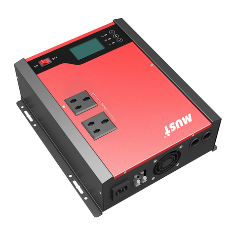
Must HBP1800 User manual

4200-100001-00A1
Please download the software “SolarPowerMonitor2.2.81”.
Download link:https://en.must-ee.com
Portable photovoltaic energy storage power station
HBP1800 1-3KW


Contents
Manual Basic Information.................................................................................................. 1
Usage ............................................................................................................................. 1
scope ............................................................................................................................. 1
SAFETY INSTRUCTIONS .................................................................................................... 1
Product introduction . ....................................................................................................... 2
Features.......................................................................................................................... 2
Basic system structure........................................................................................................2
Product Overview ..............................................................................................................3
Installatio.........................................................................................................................4
Unpacking and Inspection................................................................................................... 4
prepare............................................................................................................................4
Install equipment.............................................................................................................. 4
PV board connection..........................................................................................................5
PV Module Selection ......................................................................................................... 5
Operation ........................................................................................................................ 6
Power on/off............................................................................................................... ..... 6
Operation and Display Panel ............................................................................................... 6
LCD Display icon............................................................................................................... 7
LC D settings.................................................................................................................... 9
Fault Reference Code ................................................................................................... 14
WARNING INDICATORS.....................................................................................................16
Operating State Description......................................................................................... 17
Display Settings...............................................................................................................18
SPECIFICATIONS . ....................................................................................................... 19
Table 1 Online Mode Parameters..........................................................................................19

-1-
About the Manual
Scope: This manual describes the assembly, installation, operation and troubleshooting of this
equipment. Please read this manual carefully before installation and operation. Retain this
manual for future reference.
This manual provides safety and installation guidelines and information on tools and wiring .
The following situations are not covered by the warranty :
(1) Overdue the warranty period .
(2) The serial number has been changed or lost.
(3) The battery capacity is the lowest or the appearance of the device is damaged.
(4) External factors such as transportation,negligence,etc.
(5) This equipment has been damaged by an irresistible natural disaster .
(6) Damage caused by not following the power supply conditions or operating environment .
This manual provides safety and installation guidelines and information on tools and wiring.
Safety Notice
WARNING: This chapter contains important safety and operating instructions. Read and save this
manual for future reference.
WARNING : This chapter contains important safety and operating instructions. Read and save this
manual for future reference.
1. Before using this unit , please read all instructions and precautions on this unit , understand the
battery type and all relevant chapters in this manualto Prevent explosionwhich
may lead topersonal injury and battery damage .
2.Do not disassemble the unit . When service or repair is required , send it to a professional service
center . Incorrect assembly may result in electric shock or fire .
3. To reduce the risk of electric shock , disconnect all wiring before attempting any maintenance or
cleaning . Turning off the device does not reduce this risk .
4. Caution - Only professionals should install this device and battery .
5. Grounding Instructions - This equipment should be connected to a permanently grounded wiring
system. Be sure to comply with local requirements and regulations to use this device .
6. Never make AC output and AC input .
7. Do not move this equipment during operation, please turn off the inverter when moving.
-2-
Figure I Hybrid power generation system
Power Grid
Generator
PC
TV
Air-conditioning
Fridge
Washingmachine
Load
AC INPUT
PV INPUT
PV +-
Product Description
This is a multi-functional photovoltaic energy storage power station, integrated with battery, MPPT
solar charge controller, high frequency pure sine wave inverter and UPS function module into one ,
which is suitable for outdoor backup electric compartment and spontaneous self-use system .
MPPT charge controller adopts advanced MPPT method and intelligent battery management solar
design, which ensures the acquisition of maximum energy ;High frequency pure sine wave inverter
adopts high frequency design , achievement high rate density , small size , simple operation and other
advantages; The whole machine has high efficiency and is empty The load loss is small . Use large-
capacity basket and high-density hammer pool , Improve system portability .
Features
Pure sine Wave AC Output Inverter with 1KW - 3KW rated power and power factor 1
High power density with universal wheels and high portability.
Setting input voltage and voltage range on the LCD Screen.
5V USB and 12V DC output supported.
AC/PV input and battery priority level configurable on LCD
Protection functions such as overload, over temperature and short circuit.
Basic System Structure

-3--3-
Product Description
1. LCD display
2. Status Indicator
3. Charge/discharge Indicator
4. Indicator light
5. Function Button
6. AC input over-current protection
7. AC input
8. PV input
9. AC output
10. Switch
11. DC5V USB output
12. DC12V output
ON OFF
USB 5V
DC 12V
11
68
9
10
12

-4-
300mm
200mm
Only suitable for installation on concrete or other fire resistant surfaces
Installation
Unpacking and Inspection
Check the equipment before installation. Make sure
nothing in the package damages the product . The
followingcontainsincluded: Machine X 1
User Manual X 1
Mains input line X 1
Preparation
Before turning on the device, please reserve a distance of more than 30CM above the
device and to the left and right to ensure for heat dissipation.Input andOutput Connection
1. After power on, you can directly take power from the AC output.
2. DCoutput poweredwithout turned on.
3. Connect the grid and the AC input terminal with the matching wires to load the mains
and charge the battery.
4.Please make sure the cable is firmly connected and do not move the machine while it
is running .
Install Equipment
Taking the following notes into consideration before choosing an installation location:
1. Do not install the inverter on flammable building materials .
2. Pls installit on a sturdy surface .
3. Install this inverter at eye level so that the LCD display
can be read at any time .
4. In order to properly dissipate the air circulation, please
leave a space of about 200mm from the side and about
300mm above the device .
5. To ensure the best operation, the ambient temperature
should be between 0-50 ° C
6. It is recommended to install vertically on the wall
7. Leave a little free space around the inverter, as shown
in the picture to the right, to ensure adequate heat
dissipation and enough space to move the cables
8.heat dissipation and enough space to move the cables

-5-
Maximum charging
current 60A
power 1KW 2KW 3KW
PV open circuit
voltage
System battery
voltage
75VDC 100VDC 145VDC
Photovoltaic MPPT
voltage range cut 15-75VDC 30-80VDC 30-120VDC
12.8VDC 25.6VDC 25.6VDC
PV Panel Connection
Please choose the appropriate wire according to the matching photovoltaic panel.
PV module selection :
When choosing the right PV module, be sure to consider the following parameters:
1. The open-circuit voltage (VOC) of the PV module does not exceed the maximum open-circuit
voltage of the PV array of the inverter.
2. The open circuit voltage (VOC) of the PV module should be higher than the minimum value of the
cell voltage.
3. The maximum power point voltage of the photovoltaic array should be close to the MPPT optimal
working voltage of the inverter or within the MPPT working voltage range. If a photovoltaic module
cannot meet this requirement, it is necessary to connect the photovoltaic modules in series to meet
the requirements. See the table below.
Follow the steps below to connect the PV module:
I.Remove the 10mm positive and negative conductor insulating sleeves on
the PV inverter.
II.Check that the cable connection between the PV module and the PV input
connector is correct. Then, connect the positive (+) side of the cable to the
positive (+) side of the PV input connector. Connect the negative (-) of the
cable to the negative (-) of the PV input con

Operation
On/Off
LCD display
button
Fault
indicator Charging indicator
Status indicator
ON OFF
USB 5V
-6-
Once the unit is installed correctly,batteries is connected.The unit could be turned on by
simply pressing the on/off button (the button on the chassis).
Operating and Display Panels
The operation and display panel shown in the following figure is located on the front panel of the
inverter. It includes three indicator lights , four function keys and an LCD The display screen
indicates the running status and input and output information .
LED Indicator
LED Indicator Messages
Green
Yellow
Red
Solid On
Solid On
Flashing
Flashing
Flashing
Output is powered by grid in Line mode.
Output is powered by battery or PV in battery mode.
Battery is charging or discharging.
Fault occurs in the inverter.
Warning condition occurs in the inverter.
Function Keys
Function Keys Description
MENU
UP
DOWN
ENTER
Enter reset mode or setting mode go to previous selection.
Increase the setting data.
Decrease the setting data.
Enter setting mode and Confirm the selection in setting mode go to next
selection or exit the reset mode.

-7-
LCD Display Icons
Icon Function description
Input Source Information and Output Information
Indicates the AC information.
Indicates the DC information.
Indicate input voltage, input frequency, PV voltage, battery voltage and charger
current.
Indicate output voltage, output frequency, load in VA, load in Watt and
discharging current.
Conguration Program and Fault Information
Indicates the setting programs.
Indicates the warning and fault codes.
Warning: flashing with warning code.
Fault: lighting with fault code.
Battery Information
Indicates battery level by 0-24%, 25-49%, 50-74% and 75-100% in battery
mode and charging status in line mode.
In AC mode, it will present battery charging status.
Status Battery voltage LCD Display
Constant
Current mode /
Constant
Voltage mode
Batteries are fully charged.
> 2.167 V/cell
2.083 ~ 2.167V/cell
2 ~ 2.083V/cell
<2V/cell 4 bars will flash in turns.
Bottom bar will be on and the other three bars will
flash in turns.
Bottom two bars will be on and the other two bars
will flash in turns.
Bottom three bars will be on and the top bar will
flash.
4 bars will be on.

-8-
In battery mode, it will present battery capacity.
Load Percentage Battery Voltage LCD Display
Load >50%
< 1.717V/cell
1.717V/cell ~ 1.8V/cell
1.8 ~ 1.883V/cell
> 1.883 V/cell
50%> Load > 20%
< 1.817V/cell
1.817V/cell ~ 1.9V/cell
1.9 ~ 1.983V/cell
> 1.983V/cell
Load < 20%
< 1.867V/cell
1.867V/cell ~ 1.95V/cell
1.95 ~ 2.033V/cell
> 2.033V/cell
Load Information
Indicates overload.
Indicates the load level by 0-24%, 25-49%, 50-74% and 75-100%.
0%~24% 25%~49% 50%~74% 75%~100%
Mode Operation Information
Indicates unit connected to the mains.
Indicates unit connected to the PV panel.
Indicates load is supplied by utility power.
Indicates the solar charger is working.
Indicates the DC/AC inverter circuit is working.
Mute Operation
Indicates unit alarm is disabled.

-9-
LCD Setting
After pressing and holding "ENTER" button for 2 seconds, the unit will enter setting mode. Press
"UP"or "DOWN" button to select setting programs. And then, press "ENTER" or "MENU" button to
confirm the selection and exit.
Setting Programs:
Program Description Selectable option
Solar energy provides power to
the loads as first priority. If
battery voltage has been higher
than the setting point in
program 21 for 5 minutes, the
inverter will turn to battery
mode, solar and battery will
provide power to the load at the
same time. When the battery
voltage drops to the setting
point in program 20, the
inverter will turn to bypass
mode, utility provides power to
the load only, and the solar will
charge the battery at the same
time.
Solar energy provides power to
the loads as first priority. If
battery voltage has been higher
than the setting point in program
21 for 5 minutes, and the solar
energy has been available for 5
minutes too, the inverter will
turn to battery mode, solar and
battery will provide power to
the load at the same time.
When the battery voltage drops
to the setting point in program
20, the inverter will turn to bypass
mode, utility provides power to
the load only, and the solar will
charge the battery at the same
time.
Exit setting mode
Output source priority
selection
Escape
(default) Utility will provide power to the
loads as first priority. Solar and
battery energy will provide power
to the loads only when utility
power is not available.

-10-
AC input voltage range
If selected, acceptable AC input
voltage range will be within 90-
280VAC.
If selected, acceptable AC input
voltage range will be within
170-280VAC.
If selected, acceptable AC input
voltage range will conform to
VDE4105(184VAC-253VAC)
When the user uses the device
to connect the generator, select
the generator mode.
Set the output voltage amplitude,
(220VAC-240VAC)
Output voltage
Output frequency
Solar energy provides power to
charge battery as first priority
Solar energy provides power to
the loads as first priority
Solar supply priority
50HZ(default) 60HZ
Appliances (default)
UPS
VDE
GEN
Overload bypass: When
enabled, the unit will
transfer to line mode if
overload occurs in battery
mode.
Bypass disable Bypass enable (default)
If this inverter/charger is working in Line, Standby or
Fault mode, charger source can be programmed as
below:
Solar energy will charge battery
as first priority. Utility will charge
battery only when solar energy is
not available.
Solar first
Auto restart when
overload occurs
Auto restart when over
temperature occurs
Restart enableRestart disable
(default)
Restart enable
Restart disable
(default)
Charger source priority:
To configure charger
source priority
(default)
Solar energy and utility will charge
battery at the same time.
Solar and Utility
(default)

-11-
Solar energy will be the only
charger source no matter utility
is available or not.
If this inverter/charger is working in Battery mode or
Power saving mode, only solar energy can charge
battery. Solar energy will charge battery if it's
available and sufcient.
Only Solar
Maximum charging
current: To configure total
charging current for solar
and utility chargers.(Max.
charging current=utility
charging current +solar
charging current)
20A (default) 30A Maximum current ( )
Maximum utility charging
current
2-3KW
MPPT-50A
Setting range is from 1 A to 80A.
Increment of each click is 1A.
60A (default)
MPPT-60A
Setting range is from 1 A to 80A.
Increment of each click is 1A.
80A (default)
MPPT-80A
Setting range is from 1 A to 80A.
Increment of each click is 1A.
60A (default)
PWM-50A
Setting range is from 1 A to 100A.
Increment of each click is 1A.
100A (default)
MPPT-100A
If "User-Defined" LI is selected in program 14, this
program can be set up. Setting range is from 24.0V to
29.2V. Increment of each click is 0.1V
Bulk charging voltage
(C.V voltage)
28.2V (default)
Low DC cut off battery
voltage setting
Floating charging
voltage If "User-Defined" LI is selected in program 14, this
program can be set up, Setting range is from 24.0V to
29.2V. Increment of each click is 0.1V.
If "User-Defined" LI is selected in program 14, this
program can be set up. Setting range is from 20.0V to
24.0V. Increment of each click is 0.1V.
Low DC cut-off voltage will be fixed to setting value no
matter what percentage of load is connected.
27.0V (default)
20.4V (default)

-12-
Battery stop discharging
voltage when grid is
available
23V (default) Setting range is from 22.0V to
29.0V
Increment of each click is 0.1V
Battery stop charging
voltage when grid is
available
Setting range is from 22.0V to
29.0V.
Increment of each click is 0.1V
If selected, the display screen
will auto turn the display page.
If selected, the display screen
will stay at latest screen user
finally switches.
27.0V (default)
(default)
Auto turn page
Backlight on
Backlight control
Backlight off(default)
Alarm control
Beeps while primary
source is interrupted
Alarm on (default) Alarm off
Alarm on Alarm off (default)
Available options for 24V models:
Record Fault code
Record enable
(default)
Record disable
Solar power balance: When
enabled, solar input power
will be automatically
adjusted according to
connected load power.
Solar power balance
enable
If selected, the solar input power
will be automatically adjusted
according to the following formula:
Max. Input solar power = Max.
battery charging power +
Connected load power when the
machine in OffGrid workstate.
28 Solar power balance
disable (default)
If selected, the solar input power
will be the same to max. Battery
charging power no matter how
much loads are connected. The
max.battery charging
power will be based on the setting
current in program 11 ( Max. solar
power = Max.battery charging
power )
29 Power saving mode enable/
disable Saving mode enable If enable, the output of inverter
will be off when connected load is
pretty low or not detected.
Saving mode disable
(default) If disable, no matter connected
load is low or high, the on/off status
of inverter output will not be
effected.

-13-
31 Battery equalization voltage
Setting range is from 24.0V to 29.2V. Increment of each
click is 0.1V.
33 Battery equalization time
60min(default) Setting range is from 5 min to
900min.
Increment of each clink is 5min.
120min(default) Setting range is from 5 min to
900min.
Increment of each clink is 5min.
30days(default) Setting range is from 0 to 90days.
Increment of each clink is 1 day.
34 Battery equalization timeout
35 Equalization interval
36 Equalization activated
immediately
Enable Disable(default)
If equalization function is enabled in program 30, this
program can be set up. If “Enable”is selected in this
program, it’s to activate battery equalization immediately
and LCD main page will shows “ ”. If “Disable” is
selected, it will cancel equalization function until next
activated equalization time arrives based on program 35
setting. At this time, “ ” will be shown in LCD main
page too.
30 Battery equalization
Battery equalization Battery equalization disable(default)
28.8V (default)
After pressing and holding “MENU” button for 6 seconds, the unit will enter reset model. Press “Up”and
“DOWN” button to select programs. And then ,press “ENTER” button to exit.
Reset setting enable.
Reset setting disable.
(default)

-14-
Fault Reference Code
Fault Code Fault Event Icon on
Fan is locked when inverter is off
Inverter transformer over temperature
01
02
03
04
05
06
07
08
09
11
21
22
23
24
25
26 Inverter grid over current error
Inverter load current sensor error
Inverter grid current sensor error
Inverter output current sensor error
Inverter grid voltage sensor error
Inverter output voltage sensor error
Main relay failed
Bus soft start failed
Inverter bus voltage is too high
Overload time out
Inverter output voltage is high
Output short circuited
battery voltage is too high
battery voltage is too low
33 Solar charger current is uncontrollable
27
31
32 Solar charger current sensor error
Solar charger battery voltage class error
Inverter radiator over temperature
42
41 Inverter grid voltage is low
Inverter grid voltage is high

-15-
44
51
52
53
55
56
57
58
Inverter grid over frequency
Inverter over current protection error
Inverter bus voltage is too low
Inverter soft start failed
Over DC voltage in AC output
Battery connection is open
Inverter control current sensor error
Inverter output voltage is too low
43 Inverter grid under frequency

-16-
Fault Code Fault Event Icon on
61
62
63
64
67
70
72
73
74
75
76
77
Warning Indicator
Parameter error.
PV charger communication error.
Solar charger over temperature.
Solar charger stops due to over load.
Solar charger stops due to high PV voltage.
Solar charger stops due to low battery.
Output power derating.
Overload.
Low battery.
Battery is over-charged.
Fan 2 is locked when inverter is on.
Fan is locked when inverter is on.

-17-
Operating State Description
Operation state Description LCD display
Charge state PV energy and grid
can charge batteries.
Bypass state Error are caused by
inside circuit error or
external reasons
such as over
temperature, output
short circuited and
so on.
The inverter will
provide
output power from
battery and PV
power.
Off-Grid state Inverter power loads from PV energy
Inverter power loads from battery and PV energy
Inverter power loads from battery only
Stop mode The inverter stop
working if you turn
off the inverter by
the soft key or error
has occurred in the
condition of no grid.
PV is off
PV is on
PV energy is charger
into the battery and
utility provide power
to the AC load.
Utility-Tie state
Table of contents
Other Must Inverter manuals

Must
Must 1012C User manual

Must
Must PV1800 2K HM User manual

Must
Must PV1100 PLUS Series User manual

Must
Must PH1800 PLUS 4K User manual

Must
Must pv3500 User manual

Must
Must PV18 MPPT 3 KW User manual

Must
Must PV1100 PLUS 1200VA User manual

Must
Must PH30 Series User manual

Must
Must EP33-1024TLV User manual

Must
Must PH5000-T Series User manual