Solavita SV 7KH-S3 User manual

SV 7KH-S3 / SV 10KH-S4
SV 12KH-S5 / SV 15KH-S6
SV 17KH-S7 / SV 20KH-S8
User Manual
English

Contents
1 General information....................................................................
1.1 About this document................................................................................
1.2 Product Validity........................................................................................
1.3 Target group.............................................................................................
1.4 Symbols....................................................................................................
2 Safety........................................................................................
2.1 Intended use............................................................................................
2.2 Important safety instructions..................................................................
2.3 Symbols on the label................................................................................
3 Unpacking and storage.............................................................
3.1 Scope of delivery.....................................................................................
3.2 Product storage.......................................................................................
4 Battery System overview..........................................................
4.1 Product description.................................................................................
4.2 Dimensions..............................................................................................
4.3 LED indicator...........................................................................................
4.4 Interfaces and functions.........................................................................
5 Mounting...................................................................................
5.1 Requirements for mounting.....................................................................
5.1.1 Requirements for Installation Location...........................................
5.1.2 Tools...............................................................................................
5.1.3 Safety Gear.....................................................................................
5.1.4 Additionally Required Installation Material....................................
5.2 Mounting ...............................................................................................
1
1
1
1
2
3
3
3
6
7
7
8
9
9
10
10
12
13
13
13
15
16
16
16

6 Electrical connection.................................................................
6.1 Overview of the connection area..............................................................
6.2 Connecting the Grounding Conductor....................................................
6.3 Connecting the power cable and network cable.....................................
6.4 Parallel system connection diagram........................................................
7 Commissioning...........................................................................
7.1 Inspection before commissioning.............................................................
7.2 Commissioning procedure........................................................................
8 Decommissioning the product...................................................
9 Technical data............................................................................
10 Troubleshooting .......................................................................
11 Maintenance..............................................................................
12 Recycling and disposal..............................................................
13 EU declaration of conformity....................................................
14 Service and warranty................................................................
15 Contact.....................................................................................
22
22
22
24
27
28
28
28
30
32
34
36
37
37
38
39

General information1
This document describes the mounting, installation, commissioning, configuration, operation,
troubleshooting and decommissioning of the HB2560 battery energy storage system (BESS).
You will find the latest version of this document
and further information on the BESS in PDF
format at www.skyworthpv.com.
文档名称
It is recommended that this document be readily accessible at all times.
1.1 About this document
This document is valid for the following models:
•SV 7KH-S3
•SV 10KH-S4
•SV 12KH-S5
•SV 15KH-S6
•SV 17KH-S7
•SV 20KH-S8
1.2 Product Validity
This document is intended for qualied persons who must perform the tasks exactly as described
in this user manual.
All installation work must be performed by appropriately trained and qualied persons.
Qualied persons must possess the following skills:
•Knowledge of how batteries work and are operated.
•Knowledge of how an inverter works and is operated.
•Training in how to deal with the dangers and risks associated with installing, repairing and
using electrical devices and batteries and installations.
1.3 Target group
SV 7-20 KH
1

Information that is important for a specic topic or goal, however not related to
safety.
•Training in the installation and commissioning of electrical devices.
•Knowledge of all applicable laws, standards and directives.
•Knowledge of and compliance with this document and all safety information.
Not adhering to the prescribed instructions may potentially void the manufacturer's warranty.
If in doubt please contact the local Boneng service team.
1.4 Symbols
!Indicates a hazardous situation which, if not avoided, will result in death or
serious injury.
DANGER
!Indicates a hazardous situation which, if not avoided, could result in death or
serious injury.
WARNING
!Indicates a hazardous situation which, if not avoided, could result in minor or
moderate injury.
CAUTION
Indicates a situation which, if not avoided, can result in property damage.
NOTICE
SV 7-20 KH
2

Safety2
2.1 Intended use
The HB2560 is a BESS is for both residential and commercial applications and operates with
Boneng hybrid inverters.
•It is a high voltage Li-ion BESS controlled via a battery control unit (BCU).
•It can be operated in on-grid, off-grid and backup modes with all officially compatible
Boneng inverters.
•The product is suitable for indoor and outdoor use.
•The product must only be used as stationary equipment.
•Alterations to the product are not allowed unless authorised in writing by Boneng.
•Unauthorised alterations will void the guarantee and warranty claims. Boneng will not be
held liable for any damage caused by such unauthorised alterations.
•The product is not suitable for supplying power to life-sustaining medical devices.
•Please ensure that no personal injury would lead due to the power outage of the battery
system.
•The product must only be used in countries for which it is approved for by Boneng.
•Use this product only in accordance with the information provided in this documentation
and with the locally applicable standards and directives. Any other application may cause
personal injury or property damage.
•The type label must remain permanently attached to the product.
•This document does not replace any regional, state, provincial, federal or national laws,
regulations or standards that apply to the installation, electrical safety and use of the
product.
The product has been designed and tested in accordance with international safety requirements.
To prevent personal injury and property damage and to ensure long-term operation of theprod-
2.2 Important safety instructions
SV 7-20 KH
3

uct, read this section carefully and observe all safety information at all times.
DANGER
Danger to life due to high voltages of the battery!When the battery system connected to the inverter, and the circuit breaker is ON, the
batteries will generate a high DC voltage which will be present in the DC cable and live
components.
•Do not touch non-insulated parts or cables.
•Do not touch the DC conductors.
•Do not touch any live components of the product.
•Do not open the product.
•All work on the product must only be carried out by qualied personnel who have read and fully
understood all safety information contained in this document.
•Disconnect the product from voltage sources and ensure it cannot be reconnected before working
on the product.
•Wear suitable personal protective equipment, in accordance with local regulations, when working
on the product.
DANGER
Danger to life due to electric shock where surge protection is
not used!
If there is no surge protection, a voltage surge can be conducted into the building and to
other connected devices in the same system through power cables, network cables or other
types of cable. Touching live parts and cables may result in death or lethal injury due to
electric shock.
•Ensure all devices in the same system and the inverter are integrated within an existing surge
protection systems/devices.
•Refer to local installation regulations to determine the requirements for the installation of surge
protection devices.
SV 7-20 KH
4

Damage to the battery system due to electrostatic discharge!
Internal components of the battery system can be irreparably damaged by electrostatic
discharge.
•Ground yourself before touching any component.
WARNING
Danger to life due to electric shock from destruction of mea-
surement devices due to overvoltage!
Overvoltage can damage a measurement device and result in voltage being present in the
enclosure of the measurement device. Touching the live enclosure of the measuring device
results in death or lethal injuries due to electric shock.
•Only use measuring devices with a higher volatge range than the system battery voltage.
NOTICE
Damage to the BCU due to particles and water!
Particles such as dust and sand can damage the BCU and impair its functionality.
•Only open the BCU cover when the humidity is within the permitted range of the product and the
environment is free of dust and sand.
NOTICE
WARNING
Risk of injury due to weight of product!
Injuries may result if the product is lifted incorrectly or dropped while being transported or
mounted.
•Lift and transport the product carefully.
•Wear suitable personal protective equipment, in accordance with local regulations, when working
on the product.
SV 7-20 KH
5

2.3 Symbols on the label
Beware of a danger zone
This symbol indicates that the product must be additionally grounded if additional
grounding or equipotential bonding is required at the installation site.
Beware of high voltage and operating current!The product operates at a high voltage and current. Work on the product must only
be carried out by skilled and authorized personnel.
Beware of explosion!
The battery is an electro chemical, and there is an explosion risk in extreme cases.
Please keep away of it when the danger occurs.
Beware of danger to children!
The battery must be inaccessable to children.
Flammable
Keep the battery system away from open ames or ignition sources.
CE marking
The product complies with the requirements of the applicable EU directives.
Certication mark
The product has been tested by TÜV and obtained the quality certication mark.
RCM Mark
The product complies with the requirements of the applicable Australian standards.
The battery is recyclable
The battery can be recycled by a professional recycling organization, please refer to
the relevant local regulations.
WEEE Designation
Do not dispose of the product together with household waste. Dispose the product
in accordance with local disposal regulations for electronic waste.
Observe the documentation
Read and understand all documentation supplied with the product.
SV 7-20 KH
6

Unpacking and storage3
3.1 Scope of delivery
Check the scope of delivery for completeness and any visible external damage. Contact your
supplier if the package is damaged upon delivery or is incomplete.
BCU and Base ×1 BCU ×1 Base ×1 M5×25 Hexagon
socket head screw ×2
Documents ×1
Positive cable and
negative cable ×1
L-bracket ×2
Cable gland ×1
M5×12 Hexagon
socket head screw ×2 Terminating resistor ×1
Battery Module ×1 M5×25 Hexagon
socket head screw ×2
M6×16
Hexagon screw ×1
M8×40 Expansion
Anchor Bolt ×2
Battery Module Package:BCU and Base Package:
SV 7-20 KH
7

3.2 Product storage
Suitable storage is required if the equipment is not installed immediately:
•Store the battery in the original packing case.
•The storage temperature must be between -20°C to +45°C, and the storage relative humidi-
ty must be between 5% and 95%, non-condensing.
•The storage SOC: 25%~50%. Re-charge the battery every 6 months, to ensure no over-dis-
charge of the battery occurs.
•The packing with the equipment shall not be tilted or inverted.
•Place the equipment in a cool place away from direct sunlight.
•Keep the equipment away from ammable, explosive, and corrosive materials.
•Keep the equipment away from rain.
•The product must be fully inspected and tested by authorised personnel before it can be put
into operation, if it has been stored for three or more months.
SV 7-20 KH
8
Battery System overview4
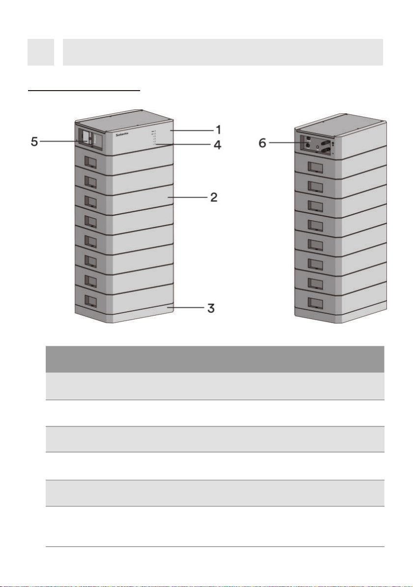
4.1 Product description
1BCU Battery control unit.
NO. Name Description
3Base The battery base which is used to support the battery.
Battery Module
HB2560 G2 battery module.
2
4LED indicator Indicate the current operating state of the battery.
5Disconnect the high voltage from battery module to BCU.
6Interface Panel
Circuit breaker
The interface panel containing ON/OFF , DC connectors
and the “Link Port In” which is used to connect the BCU to
the connected battery module.
SV 7-20 KH
9

LED status denitions:
•Solid On: LED is permanently illuminated.
•O: LED is o (is not illuminated).
•Blinking: LED illuminates for 1 second and turns o for 1 second.
•Pulsing: LED illuminates for 1.5 seconds and turns o for 5 seconds.
4.2 Dimensions
4.3 LED indicator
Unit:mm
The LED’s on the BCU indicates the status of the BESS.
Indicates an alarm.
Status
Description
LED
Function
Solid ON BCU is power on, and the battery is waiting
to turn on.
Blinking
SV 7-20 KH
10

SOC:60%~80%
SOC:40%~60%
SOC
Normal state.
SOC:80%~100%
Solid ON Indicates a fault.
ON
ON
ON
ON
ON
OFF
ON
ON
ON
ON
OFF
OFF
OFF
ON
ON
OFF
OFF
ON
ON
ON
OFF
OFF
OFF
OFF
ON
OFF
SOC:20%~40%
SOC:0%~20%
SOC
SOC
SOC
SOC
SV 7-20 KH
11

There are ve LEDs to indicate the State of Charge (SOC) of the battery, and the
dierent status of the LEDs indicates the dierent working state of the battery.
•Solid ON indicate discharging state.
•Blinking On indicate Charging state.
•Pulsing ON indicate standby state.
4.4 Interfaces and functions
The product is equipped with the following interfaces and functions:
Communication (CAN) Interface - “Link Port”
The “Link Port” is an RJ45 port used for connecting the BCU to an inverter. The product can
communication with the inverter through the CAN interfaces. And the CAN interfaces also can
be used for the parallal operation of the products.
System startup
Turn on the circuit breaker. When the status indicator turns yellow, press the button for at least
3s, all lights will turn on from bottom to top, Pack is in working mode, and the device can be
charged and discharged normally.
System sleep
Press the button for at least 5s. Make sure that both the SOC indicator and the status indica-
tor of the control unit are o.
System shut down
Turn o the
circuit
breaker.Make sure that both the SOC indicator and the status indicator of
the control unit are o.
SV 7-20 KH
12

DANGER
!Danger to life due to re or explosion!Despite careful construction, electrical devices can cause res. This can result in death or
serious injury.
•Do not mount the product in areas containing highly ammable materials or gases.
•Do not mount the inverter in areas where there is a risk of explosion.
•A solid support surface must be available (e.g. concrete or masonry).
• The mounting location must be inaccessible to children.
• The installation location must be suitable for the weight and dimensions of the BESS.
•Keep away from conductive (metal) dust.
•Keep away from water sources, heat sources and inammable and explosive articles.
•The installation location must not be close to re.
•The product should be mounted such that the LED indicators can be read without diculty.
•The circuit breaker of the BESS must always be freely accessible.
• The altitude of the installation location should be less than 3000m.
•The operating temperature should be between -20 °C ~ +50 °C.
• The ambient humidity should be between 5-95%.
•The mounting location must not be exposed to direct solar irradiation. If the product is
exposed to direct solar irradiation, the exterior components may age prematurely and
overheating might occur. When becoming too hot, the BESS reduces its power output to
avoid overheating, and will reduce its lifetime also.
Mounting5
5.1 Requirements for mounting
5.1.1 Requirements for Installation Location
SV 7-20 KH
13

-20°C
+50°C
RH.+5%~+95% max.3000m
×××
√√√
IP65
SV 7-20 KH
14

5.1.2 Tools
The tools in the following table may be needed during the installation.
Phillips-screwdriver
Specication:M4 Marker pen Phillips Screwdriver Bit Wrench
Torque wrench Hexagon socket bit S=4 Hair Dryer
Tape measure
Electric Drill Network Wire Clamp Wire Stripper Crimping Pliers
Scissor Hammer
Ratchet wrench
Hey Key S=4
SV 7-20 KH
15

DANGER
Danger to life due to high voltages of the battery!When the battery system connected to the inverter, and the circuit breaker is ON, the
batteries will generate a high DC voltage which will be present in the DC cable and live
components.
•Do not touch non-insulated parts or cables.
•Do not touch the DC conductors.
•Do not touch any live components of the product.
•Do not open the product.
•All work on the product must only be carried out by qualied personnel who have read and fully
understood all safety information contained in this document.
•Disconnect the product from voltage sources and ensure it cannot be reconnected before working
on the product.
•Wear suitable personal protective equipment, in accordance with local regulations, when working
on the product.
5.2 Mounting
5.1.3 Safety Gear
5.1.4 Additionally Required Installation Material
Network Cable PE Terminal PE Cable Heat Shrink
Insulated gloves Safety goggles Safety shoes
Wear the following safety gear when working on the BESS. Adhere to local occupational health
and safety standards.
SV 7-20 KH
16

Step 1:Remove the BCU and the base from the package and then separate the BCU and the
base by removing the two screws(M5×25) that hold are holding them together.
M5 N.W: 15kg
WARNING
Risk of injury due to weight of product!
Injuries may result if the product is lifted incorrectly or dropped while being transported or
mounted.
•Lift and transport the product carefully.
•Wear suitable personal protective equipment, in accordance with local regulations, when working
on the product.
SV 7-20 KH
17
This manual suits for next models
5
Table of contents
Other Solavita Inverter manuals

Popular Inverter manuals by other brands

Hoymiles
Hoymiles HMS-800-2T Quick installation guide

Sensata
Sensata Dimensions 12LPC15 owner's manual

MGI
MGI M4000E series instruction manual

Xantrex
Xantrex SW Plus 2524 owner's manual

Base aire
Base aire O-UVC2 Pro Installation & operation manual

Mitsubishi Electric
Mitsubishi Electric FR-F820-00046 instruction manual


Black & Decker
Black & Decker BDI750 instruction manual

IOTA
IOTA IIS 550 I instruction manual

PulseTech
PulseTech SP-7-OBD-A installation manual

SMA Solar Technology AG
SMA Solar Technology AG SUNNY TRIPOWER 15000TL operating manual

SamplexPower
SamplexPower SAM-250-12 owner's manual

Sofar
Sofar Sunny Deer Series user manual