Sofar Sunny Deer Series User manual

PV Grid-Connected Inverter
Shenzhen SOFARSOLAR Co.,Ltd
Product Name: PV Grid-Connected Inverter
Company Name: ShenzhenSOFARSOLARCo.,Ltd
ADD: 3A,Huake Building,East Tech.Park,Qiaoxiang Road,Nanshan District,Shezhen,China
Http://www.sofarsolar.com
Product Model:Sunny Deer Series(3K-5KTLM)Document Version 1.0(2014.07.20)
User manual
S
:~
FAR
--
~~r.
_
'?.:'.'!.
_
~
-
~
-
~~-"-~~
-
~
--
-
~
-
~!
-
~~)
____________________________________________________________________________________________________________________
_
5c::::::IL.AI===I
Usermanual
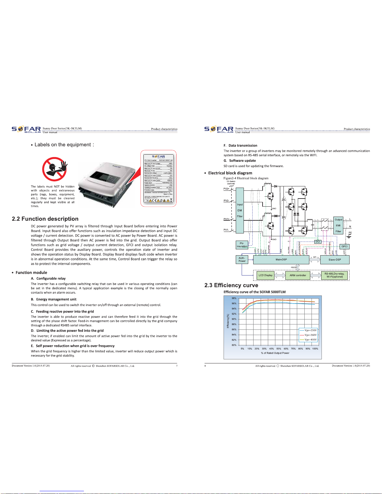
Notice
This manual contains important safety instructions that must
be
followed during installation
and maintenance
ofthe
equipment.
Save these instructions!
This manual must
be
considered
as
an
integral part
of
the equipment, and must
be
available
at all times
to
everyone who interacts with the equipment. The manual must always
accompany the equipment, even when
it
is
transferred
to
another user
or
field.
Copyright Declaration
The
copyright
of
this manual belongs
to
Shenzhen
SOFARSOLAR
Co.,
Ltd.
Any corporation
or
individual should not plagiarize, partially copy
or
fully copy
it
(including software, etc.), and
no reproduction
or
distribution
of
it
in any form
or
by any means. All rights reserved.
SOLARSOFAR
reserves the right
of
final interpretation. This manual
is
subject
to
change
according
to
user's
or
customer's
feedback.
Please
check
our
website
at
http:/
/www.sofarsolar.com
for
latest version.
Shenzhen SOFARSOLAR Co
.,
Ltd.
ADD:
3A,Huake
Building,East
Tech.Park,Qiaoxiang
Road,Nanshan
District,Shezhen,China
Http://www.
sofarsolar.
com
p_
c_,
s1aooo
E-mail:[email protected]
DocumentVersion 1.0(2014.07.20) Allrights reserved © Shenzhen SOFARSOLAR Co
.,
Ltd.
S
~
~
FAR
-
~~r.
_
'?.:~:.
-
~
-
~!!
-
~.s.~~
-
~
-
:
~
-
~!
-
~~)
----------------------------------------------------------------------------------------------------------
-
~r.~
-
~
sc::::::JLA.-===t
Usermanual
Preface
Outline
·Scope
Please
read the product manual carefully before installation, operation or maintenance. This
manual contains important safety instructions and installation instructions that must
be
followed during installation and maintenance
of
the equipment.
This product manual describes the installation, electrical connections, commissioning,
maintenance and troubleshooting
of
Sunny Deer series inverters:
SO
FAR
3000TLM
SO
FAR
3680TLM
SO
FAR
4000TLM
SO
FAR
4600TLM
SO
FAR
SOOOTLM
Keep
this manual where
it
will
be
accessible at all times.
• Target Group
This manual
is
intended
for
qualified electrical technical personnel who are responsible for
inverter installation and commissioning in the
PV
power system and the
PV
plant operator.
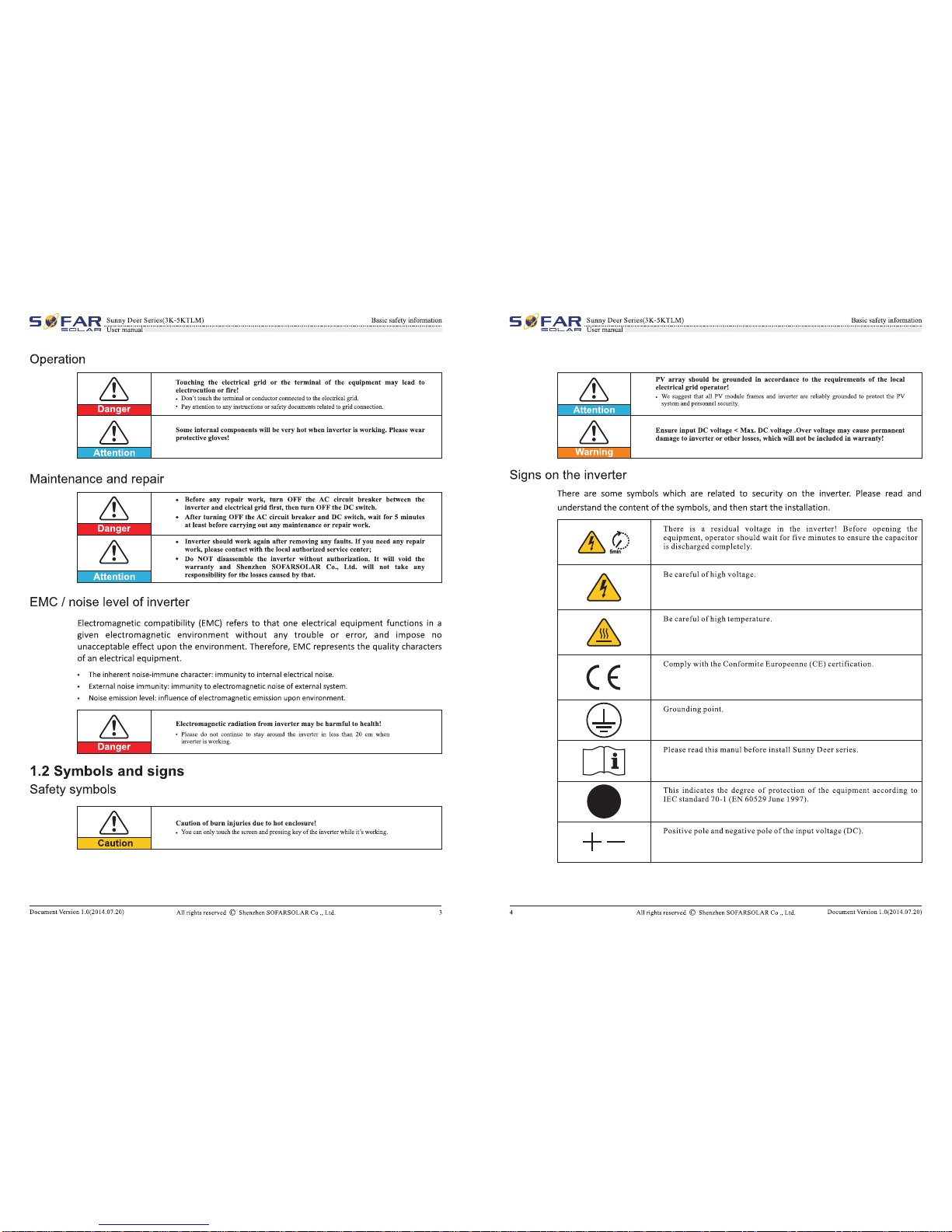
·Symbols
Used
This manual provides safety operation information and
uses
the symbol in order
to
ensure
personal and property security and
use
the inverter efficiently when operating the inverter.
You
must understand these emphasized information
to
avoid the personal injury and
property
loss.
Please
read the following symbols used in this manual carefully.
& Danger indicates a hazardous situation which,
if
not avoided,
will
result
in death
or
serious injury.
-·-
·~
& Warning indicates a hazardous situation which,
if
not avoided, could
result in death
or
serious injury.
,.
!F.TToT
.
& Caution indicates a hazardous situation which,
if
not avoided, could
result in minor
or
moderate injury.
Caution
& Attention indicated potential risks which,
if
not avoided, may lead to
equipment fault
or
property damage.
,.,
;r."~
.m
(@?
Note provides tips
that
are valuable for the optimal operation
of
the
product.
-,.
DocumentVersion 1.0(2014.07.20) All rights reserved © Shenzhen SOFARSOLAR
Co.,
Ltd.
II
S
:~
FAR
--
~~r.
_
'?.:"!.
_
~
-
~
-
~~-"-~~
-
~
--
-
~
-
~!
-
~~)
_____________________________________________________________________________________________
!~E!!'.
.
~!~Il~~~
5c::::::IL.AI===I
Usermanual
Table
of
contents
Preface
....................................................................................................................................................................................................
II
1 Basic safety information
...............................................................................................................
1
1.1 Safety
instructions
..............................................................................................................................................................................................
.
1.2 Symbols
and
signs..................................................................................................................................................................................................
3
2
Product
characteristics
.................................................................................................................
. 5
2.1
Product
identification
···
-·-·-·- ·-·-·-·-·-·-·-·-
································································
-·-·-·- ·-·-·-·-·-·-·-·-·-·-·-
·········
5
2.2
Function
description..........................................................................................................................................................................................
7
2.3 Efficiency
curve
......................................................................................................................................................................................................
8
3
Installation............................................................................................................................................
9
3.1
Installation
Process·-·-·-·-·-·-
································································
-·-·-·- ·-·-·-·-·-·-·-·-·-·-
················································
9
3.2
Checking
Before
Installation.....................................................................................................................................................................
9
3.3
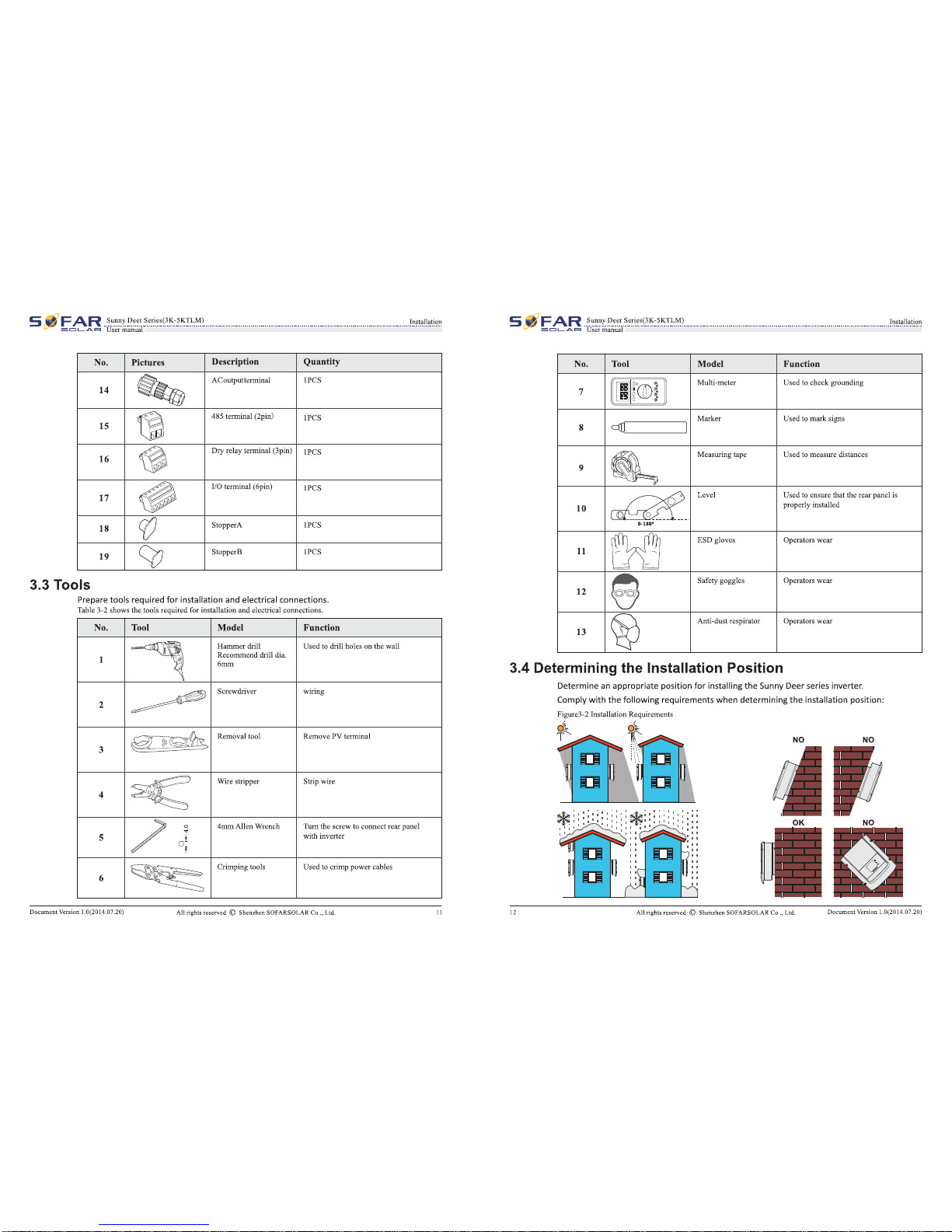
Tools.....................................................................................................................................................................................................................................
11
3.4
Determining
the
Installation
Position..............................................................................................................................................
12
3.5 Moving
the
Sunny
Deer
series
inverte~:...........................................................................................................................................
14
3.6
Installing
Sunny
Deer
series
inverteJ."................................................................................................................................................
15
4 Electrical Connections
.....................................................................................................................
16
4.1
Electrical
connection·
-·-·-·-·-·-·-·-·-
................................................................
...
.
...
.
...
.
...
.
...
.
...
.
...
.
...
.
...
.
...
.
...
.
...
.
...
.
...
.
...
...........................
16
4.2
Connecting
PGND
Cables..............................................................................................................................................................................
17
4.3
Connecting
DC
Input
Power
Cables..................................................................................................................................................
18
4.4
Connecting
AC
Output
Power
Cables..............................................................
...
.
...
.
...
.
...
.
...
.
...
.
...
.
...
.
...
.
...
.
...
.
...
.
...
.
...
.
...
.....................
20
4.5
Connecting
Communications
Cables
..............................................................................................................................................
23
4.6
Communication
method.................................................................................................................................................................................
26
5 Commissioning
of
inverter:
..........................................................................................................
29
5.1 Safety
inspection
before
commissioning.......................................................................................................................................
29
5.2
Start
inverter..............................................................................................................................................................................................................
29
DocumentVersion 1.0(2014.07.20) Allrights reserved © Shenzhen SOFARSOLAR Co
.,
Ltd.
III
S
~
~
FAR
-
~~r.
.
'?.:~:.
-
~
-
~.r.i
-
~.s.~~
-
~
-
:
~
-
~!
-
~~)
_____________________________________________________________________________________________
!~E!!'.
.
~!!!"-11~!~
sc::::::JLA.-===t
Usermanual
6 Operation interface
...........................................................................................................................
30
6.1
Operation
and
Display
Panel
______________________________
........................................................................................................................................
30
6.2
Standard
Interface................................................................................................................................................................................................
31
6.3
Main
Interface..........................................................................................................................................................................................................
33
6.4
Update
Software
online...................................................................................................................................................................................
41
7 Trouble shooting
and
maintenance.......................................................................................
43
7.1
Trouble
shooting·····································································································································································································
43
7.2
Maintenance................................................................................................................................................................................................................
47
8 Technical
data
.......................................................................................................................................
48
8.1
Input
parameter
(DC)........................................................................................................................................................................................
48
8.2
Output
parameter
(AC>...................................................................................................................................................................................
48
8.3 Efficiency, Safety
and
Protection..........................................................................................................................................................
49
8.4
General
Data...............................................................................................................................................................................................................
49
9 Sofar SolarMAN Quick_Setup
Manual
(Wi-Fi Optional)
...................................
50
9.1
Network
setting........................................................................................................................................................................................................
50
9.2
Register
on
Solar
MAN
Portal...................................................................................................................................................................
58
9.3 Log in
Solar
MAN
Portal
to
manage
power
station.........................
...
.
...
.
...
.
...
.
...
.
...
.
...
.
...
.
...
.
...
.
...
.
...
.
...
.
...
.
...
..........................
60
10 QualityAssurance
...........................................................................................................................
62
DocumentVersion 1.0(2014.07.20) All rights reserved © Shenzhen SOFARSOLAR
Co.,
Ltd. IV

___
BoAo
= '
:.:
oafoty=
~
JL
Basic safety information
BJW
ILimo..,
~or
pnlbkm-
~
t11o
~-
r
iPieLio
-SIIoall!.o&
IIOFAJlSOI.aC..,.
lAd.
Outlines ofthis chapter
Safety instruction
It
malnlv
lrmod~
thesafety
lnstl"Uctkln
when
Install
and
ap~
theequlpmetlt.
Symbols
and
signs
It
malnlv
lntrodua!thesafety
symbols
on the
Inverter.
1.1
Safety instructions
•
Read
and undmtand the
instl"Uctions
of
this
manual,
;rnd
be
t.rmili;rr
wi1h
relevant safety
symbols
in
this
d1apter,
then
stirrt
to
install
and
traubl~hoot
1tle
equipment.
• A«ordlll8
to
the
national
and
state
requirements, before
connectln,s
to
the
electrical
grid,
you must
get
permission
from
the
local
electrlcalsrldoperator, and the operation
can
antv
be
performed
by
qualified
electrical
en,sineer.
•
Please
contact
1tle
nearest
alllhorlzed
servloe
oenter
If
any
malntetlanoe
or repair
Is
needed.
Contact
your distributor for
1tle
Information
of
the nearest authartzed
.servloe
oel!tef.
Do
NOT
repair
It
b!fvourselt;
It
may
cause lnjurvor
prapl!t't!fdamage.
•
B!!fore
In
smiling
and
malrrtllnlng
1tle
equipment,
vou
sflould
turn
1tle
DC
switch
OFF
to
out
off
1tle
high
vorta,se
DC
ofthe
PV
array.
You
can
alsotum
1tle
switch
In
1tle
PV
combiner
box
OFF
to
cut
off
the
high
voltage
DC.
otherwise,serious
lnJurv
may
becaused.
Qualified
persons
Ma~
sure theoperator
has
1tle
nec:euarv
skill
and
tralnln,s
t1>
do his/herjob.
Staff
In
charae
of
usin,s
and maintaininsthe equipment
must
be
skilled,
aware and mature
for
thedescribed
tasks
and
must
haft1he
reli;rbility
1o
correl:ltv
interpret what
is
desl:ribed
in
the
manu;rl,
For
Safety
reasons
ontv
a qu;lified electrician,
who
has receiwd
1r.linins
and
I or has
demonstrated
skills
and
know!ed;ge
In
construction
and
In
operation
of
this
device,
can
Install
this lnwrter.
Shenzhen
SOFAASOI.AR
Co.,
Ltd.
does not taka
any
responsibility
for the
propertydestruction and
personal
InJury
caused
by
any
Incorrect
use.
--I.O(U)14Jf1.l:O)
s .<
FAR
s_,.J>-Sorin(31t-
:.:
5JJLU}
==-
---
-Cl-A.-
Ua
fiiliDil
Installation requirements
PINse
Install
Inverter
according
to
the
followln,s
section.
Fix
the
Inverter
an an appropriate
objects
with
etlou,sh
load
bNrln,s
capacity
(such
as
walls,
PV
racks
¢),
and
er.sure that
inverteris
vertical
placed.
Choose
a placesuitable for inrtallins
electrical
cSevices.
And
assure
there
is
enoush
fire
!:!Kit
SPice,
convenient for maintenance.
Maintain
prapK wntilation to
etlsure enoushaircycle to
cool
theirMrter.
Transport
requirements
If
you
find
packing
problems
1tlat
mav
cause the
damap
of
the
Inverter,
or
find
any
visible
damap, please
lmmedlatel!f
notloe
1tle
nesponslble
transporta!San
company.
You
can ask
.syour
solar
system
Installer
or
Shenzflen
SOFARSOI.AR
Co.,
Ltd.
for
help
If
neoessarv.
Transport
of1tle
equipment,.
espedall!f
by
road,
must
be
carried
out
wtth
suitable
means
for
protecting
the components
(In
pal'tfcular,
the
electronic
components)
from
violent
sflor:ks,
humidity,
vlbralkln,
etc.
Electricconnection
2
Please
compl!f
with
all
thecurrent
electrical
nesulations
aboutaccident prevention
in
deal
ins
with
the
sol~r
lnwrter.
......
tll6~_,-
.........
______
.,
PV_..,.to_PV_..DC-~tolb-PV"""'7
'11111~.-...-~1
Alllll.llllllollo:•-mpWiMI...,t,...-.--~
• mutbtll:llil:llcl;
·~---~----
IP65
100
60
2650
900
1775
850860
3140
259
350
C
2x
2x

S
.;;t
FAR
-
~~r.
-
~~~
-
~
-
~
~
!
-
~!.{~~
-
:
~
-
~!
-
~
~
L
__________________________________________________________________________________________________
~
-
~!i!!!!
sac:::IL
...
AF=>
Usermanual -
3>
Installation
Outlines
of
this chapter
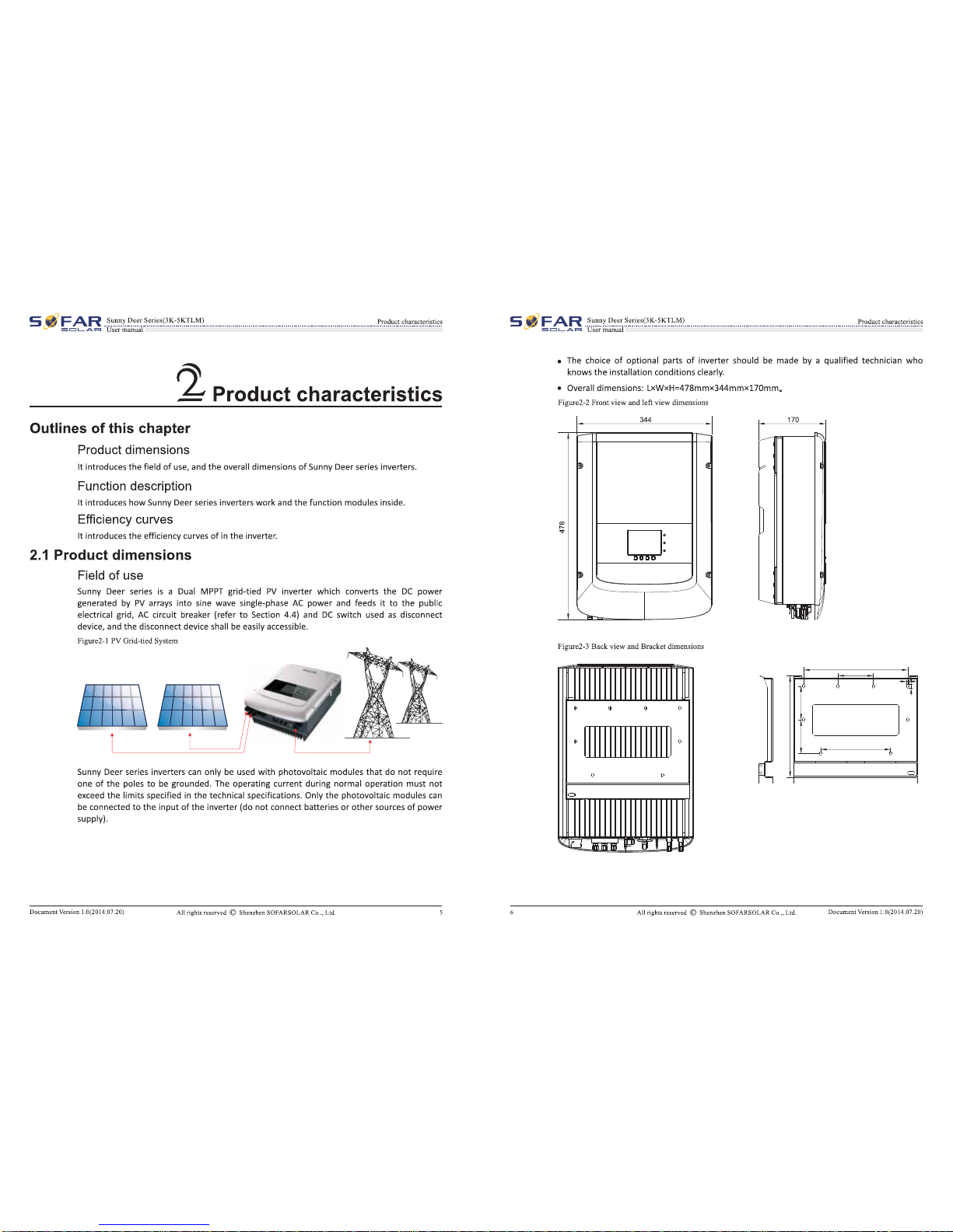
This topic describes
how
to
install theSunny Deer series inverter.
Installation notes
~
• Do
NOT
illltall
the
Suuuy
Deer
series ona flammable materiaL
.Do NOT Install
the
Sunny Deerseries
In
an
area
nsed
to
otore flammable
or
-··
!'._
explosive materials.
~
The enclooure
and
beat
sink
are
very
bot
wbDe
the
Inverter
Is
working,
therefore
do
NOT
Install
the
Sunny
Deer serieo
In
placeo where yon might
touch
them
inadvertently.
Caution
~
.Con1ider
the
weight
of
Sunny
Deer
series
when
transporting
and
moving
the
Sunny
Deer
Serleslnverten.
.Choooe
an
appropriate
mounting
poaition
and
surface.
'~"[-
I!TiTil .Aaoign
at
leasttwo peraon•
to
illltall
the
Sunny
Deer
oerieoinverter.
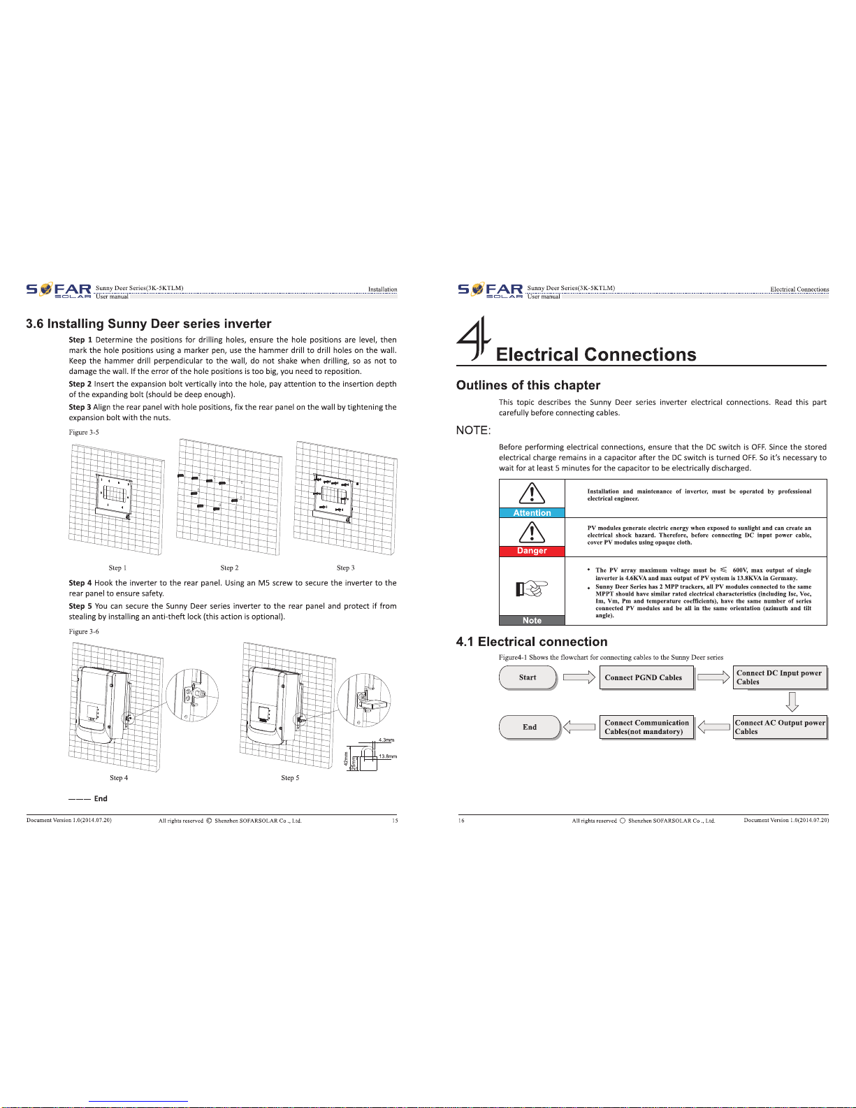
3.1
Installation Process
Figure3-1 Installationflowchart
(
Start
) ¢
'-
~
-
!
_
:!na
_
k
_
~
_
~
_
!
_
re
.....
¢I
3.2 Checking Before Installation
Checking Outer Packing Materials
Prepare
instaUation I
~
Determine
the
tools •
'------V
installation position
~
Packing materials and components may
be
damaged during transportation. Therefore, check
the
outer packing materials before installing
the
inverter. Check
the
outer
packing materials
for
damage, such
as
holes and cracks.
If
any damage is found,
do
not
unpack the Sunny Deer
series and contact the dealer
as
soon
as
possible.
You
are advised
to
remove
the
packing
materials within 24hours before installing
the
SunnyDeerseries inverter.
Checking Deliverables
After
unpacking
the
inverter, check whether deliverables are intact and complete.
If
any
damage is found
or
any component is missing, contact the dealer.
DocumentVersioo 1.0(2014.07.20)
All
right
sr
..
erved
© ShenzhenSOFARSOLAR Co
.•
Ltd
.
S
':t
FAR
-
~~r.
-
~
~
~E
-
~
-
~!!
-
~!
.
{~!!:.
:
~
-
~!~L
................
...
............
.....
....
.
.....................
.
......................
.....
...
.
.....
~
-
~m;
sacL-AF=>
Usermanual
Table3-l shows
the
components
and
mechanicalpartsthat should
be
delivered
No. Pictures Description Quantity
~
SunnyDeer Series 1
pes
1
~
Rearpanel I
pes
2
IP
PV+
inputtcmtinal
2pcs
3 # PV-input tcmtinal
2pcs
4 I Metal terminals secured
2pcs
5 to
PV+
input
power
cables
I Metal tcmtinals secured
2pcs
6 to PV- input
power
cables
~
M5 Hexagon screws
2pcs
7
~
M6 flatwasher
lOpes
8
~
Expansion
bolts
10pcs(spare 2pcs)
9 / Self-tapping screw
Spes
10
~
Manual 1
pes
11
~
The
WSITBDty
card 1
pes
12
$ Certificate 1
pes
13
10
All
rights
reserved © Shenzhen
SO
F
ARSOLAR
C
o.
, L
td
. DocumentVersion 1.0(2014.07.20)
OK OK NO OK
OK OK NO
NO
NO

C
max 15º
C

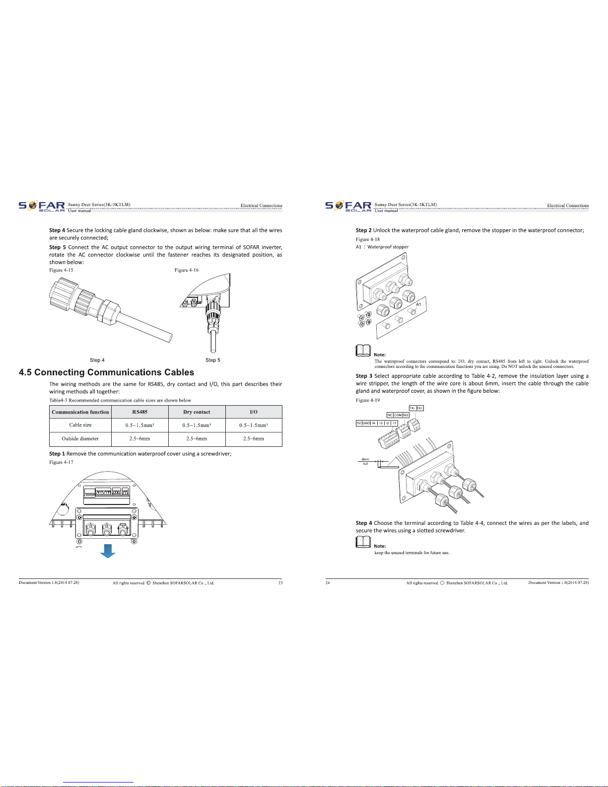
4.2
ConnecOng
PGND
Cabin
Cllnnll<l: tho
SUnny
Doer
Hrlooll>
th
arounlf1111
oloctrcde
wfllll
pnolll<tlon
(I'QIInd
{PGND}
cables
for
8RIUMIII1fl
purposes,
·-·k
7
___
...
.,....,.
__
,.
...
..
.,..._
....
Mil'
__
...
___
......
"
.......
,...,.
....
..-t~.,...fll!atiJ(nllllll•"-a:Jo
_"'.....,_'-
____
..
_
·-
,,.
""q"
1
t.»a
~
The
PGND
cablesart'
prep;ftd
(;o5mrW-
04Jidoor
powef
c.1bles
are
reoam--
for
-.ndl111-1the
...,,..
ofubl•""""ld
be
yol--n.
,,_..,,.,
Ste!t
1
Rem
owthe nwllltlon
r_.
Willi
en
eppnoprllte
lelllllh
Ullni
awire
Stlfpper,
as
"'-n
In
Flpft4-2.
l'Spa4-1
........
....,.,...lolo(l)
I I L2ot.1+!2-SJmm
_,
uu2
..
-....,._u
Slle!tllnsert
11>e
~care
""resInto
til~
ar
UITI'inalandafrnp
them
bv
UIIMi
• crfmllina
tool,u
ohown
In
f'WIIrw
<1-3.
lll;taro4-$
l'!:copolq•lfi"''DD•Io(2)
~
LF·------------~~
-··
UiJdlolaooll>-dloioooldioo..,..,
.........
oo»J..tdlo~.,.U..iltbo--lloo
""""''*'"""--~-
...
~-
-S:
·---~
...
-
.....
...,-
.............
-~~---
_l!lo_._
Stoop
3 lnslallthe(limped OTtllnrinel,!lotwasherlllfllilMS......,.,
and~
the
,.,_toa
~ue
of
3
N.rn
uslllfl
en
Allen
wmu:l\.
--IA(2014#7JO}
"
fl~
It_
"-
'
~
\
~
._ -.,,!
~
1.
MS«n'W J. Rill__._
s..
or....,..
..
._
..,._...,..
4.3
Connecting
DC
Input
Power
Cabin
•.n.•
,_.,..
5"P1
~ca.llleiJends
from
theposltM!
end~--.
Slllf
2
Remove
1he
lnsulalfonla)'erw!lll
en
jippf0111111e
l~&lh
from
the
PDSIIM!
and
nep1llle
-
c:obles
bv
U1111,1a
"""'
strlpfll!r•
ti1crw
In
'"""'
4-S.
F"1FNUC
r
IDC;,pot--
1.1410~
.
~
I' 9
I
I • 1§1]8
w 1
U4t0nYn
• I I.
I I I g
~
2
1.
Poe-
power
cable
2.
NegdYe
poww
cSII&
&-

5 ..
FAR
SmmyDaarSorioo(31t·
.:.:
'l:iLM}
==-
-·----
-Cl-A.JIIl
U•mmmal
-------
~
~~
~
Stlap
SInsertthepositive
and
negative
power
cables
Into
oorrespondlng
cable
pands.
S'llep
4
ln:sert
the stripped positive
and
ne,pt~
power
cables
Into the
posit~
and neptlve
rnetll
tllfmin~ls
respectively
and
crimp
1hem
winga
cl~mpina
tool.
Ensure
thatthe
cables
are
crimpeduntiltfleycannot
be
pulledout
by
force
less
than 400
N,
as
shown
In
Flgune
4-6.
Fip:\14-6
~DC
illp1ll
P""""
w.blw
1.l'oi--CIIblo
2.Nop!Mt-rallll
Steps
In~
crimped
power
cables
Into
oorrespondlng
houslnas
until
you
hear
a
"dick"
sound.
The
power
cables
snap
Intoplaoe.
Step6
Reinstall
cable
slands
on
positive
and
nesatlve
connectors
and~
them apll\stthe
lnsul<rtion
CIO'III!rs.
Stlp
7 Insert the
positi¥e
and
neaative
oonnectars
into
oorresponding
DC
input
tllfmin~ls
of
the
Sunny
D~r
Series untilyou
hear
a
"click"
sound,
as
shown
In
Figure
4-7.
Fi&urc
4-7Com!.cc:tiqDCillp1llpower
cab
lea
,
d
--
...
1.0(1014.07.10)
19
5 ,
FAR
S>m!!JDoorSc!rioe(U.·R'i"LM)
-Ci-A-
Ulll!ll'J:rliiD:IIl
Fell
low-up Proceclure
To
remove
the positive
and
negative
oonnectors
fromthe
Sunny-
D~r
Sl!fles,
Inserta
rem011al
wrench
Into
1he
bayonet
and
press
the
wrench
with
an
appropriate strength,
as
shown
In
Figure+S.
Caullan
4.4
ConnecOng
AC
Output Power Cables
Connect
the
SUnny
Deer
Seriesto
1he
AC
powerdistribution frame
(PDF)
or
power
grfd
uslns
AC
outputpower
cables.
Caullan
Contut
•llllaot.......,rt.r~m-~-·-drcwlt.,......,
•llloaot.....alo-'lacllw--.-.dmdlb:nlli;m;,
All the
AI:.
output
cables
used
forthe lnvertl!fs
ane
outdoorthree-core
cables.
To
facllltatl!
1he
lnstaii&Uon,
use
fleldble
cables.
Table
4-Z
liststhe
recommended
speclflcatlons
for
1he
cables.
'l'loblo4-Uoc
~IIIIKittldo
~AC~cebk>~
Model So&r30tOTI.M So&rUJOTI.M 8ofap400tTLM
8ofap
4al'LM
8ofap
5tOOTLM
Cebk(Ccppcr} ;»4mm• ;;.
4111m"
..
4mm*
;»5mm* ;»5mm'
ClmPtll!oabr
:2IJAI.t3
OVI.lP/0
.lA
2S.v.tlOVI2P/O.IA
'J.SNZj~Nf.lP/O.IA
32A/230V/2P/O.IA
32A/230VIl'PIO.IA
--1.0(2014.D'I.j.())
C
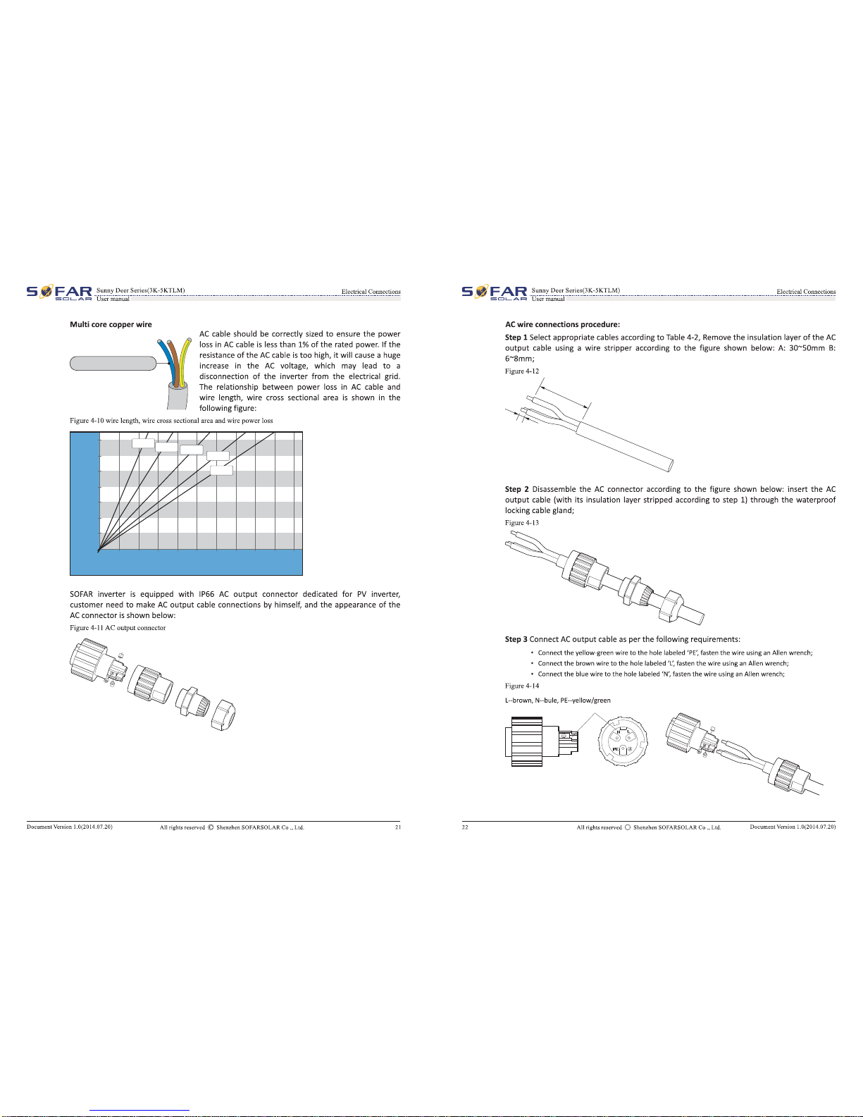
Multi core copper wire mm²≥4
0m 10m 20m 30m 40m 50m 60m 70m 80m 90m 100m
1.4%
1.2%
1.0%
0.8%
0.6%
0.4%
0.2%
0.0%
Loss
Length
2.5mm² 4.0mm² 6.0mm² 8.0mm²
10.0mm²
A
B
C

USB
RS 485
-
R 485/USB
S
R 485
S
Radio ripple
control receiver Publlc Grid

-
USB
RS 485
R 485/USB
S
R 485
SR 485
SR 485
S
Radio ripple
control receiver Publlc Grid

S
~FAR
..
8
~~
-
~~~
-
~
-
~(3~--
-
~~!L~
-----·-··---···-··---···-·---····---······---·····----
~!~o~
-
~~
!::ic::JL...
A.l==l
UIICI'
manual
-
5>
Commissioning
of
inverter
5.1
Safetyinspection before commissioning
5.2 Start inverter
Ensare
tbat
DC
and
AC
voltagea
are
within
the
acceptable
range
of
the
Sunny
Deer
aeriesInverter.
Step
1:
Turn
ON
the
DC
switch.(optional)
Step
2.:
Turn
ON
the
AC
circuit breaker.
When
the
DC
power
generated
by
the
solar arrayis adequate,
the
Sunny Deer series inverter
will
start
automatically. Screen showing
"normal"
indicates correctoperation.
If
the
inverter indicates any fault, please refer
to
Section 7.1
of
this manual
--
trouble
shooting
for
help.
DOOIII!lellt
Version 1.0(2014.07.20)
All
righ1areoerved ©
Shenzhen
SOFARSOLAR
Co
.•Ltd. 29
S
~
FAR
_
s~~
-
~!!:
-
~
.
~~
-
~•(3~
.
:
~TL~
--
-··-····
·
···-····
·
···-
·····
····-···
·
····-·
·
······-········--
~
-
~
-
~
!::ic:::JL...A.R
U1crmanual
(6)Operation interface
Outlines
of
this
chapter
This section introduces
the
display, operation, buttons and
LED
indicatorlights
of
Sunny Deer
Series Inverter.
6.1
Operation and Display Panel
• Buttons and Indicator lights
Key-button:
GFCI
Warning
Inverter
States
Li
ght
Warning Light
• Back
11:
to
return
to
previous menu
or
enter
into
main menu
from
the
standard interface.
30
• Up
1f:
to
move
up
or
increase val
ue
• Down.ij.:
to
move
down
or
decreasevalue
•
OK~:
to
confirm selection
IndicatorLights:
• InverterStates Light(
GREEN)
Flashing:
'Wait'
or
'Ciwck' state
ON:
'Nmmal'
state
OFF:
'Fault'
or
'Pen:nanent'
state
• Warning Light
(RED)
ON:
'Fault'
or
'Permanent' slllte
OFF:
'Nmmal'
state
•
GFCI
Warning Light
(RED)
ON:
'IDI2:
GFCIFanlt'
or
'ID20: GFCIDeviceFanlt'
OFF:GFCI1l01'1118l.
Allrigblareoervod © Shi:DzhenSOFARSOLAR
Co
.•Ltd.
DOOIII!lelltVonion
1.0(2014.07.20)
Initializing…
Wait 10s Waiting StatesCountdown 10S

S
:~
FAR
--
~~r.
.
'?.:"!.
.
~
-
~
-
~~-"-~~
-
~
--
-
~
-
~!
-
~~)
__________________________________________________________________________________________
?.P.~~~
-
~!~~
-
~
5c::::::IL.AI===I
Usermanual
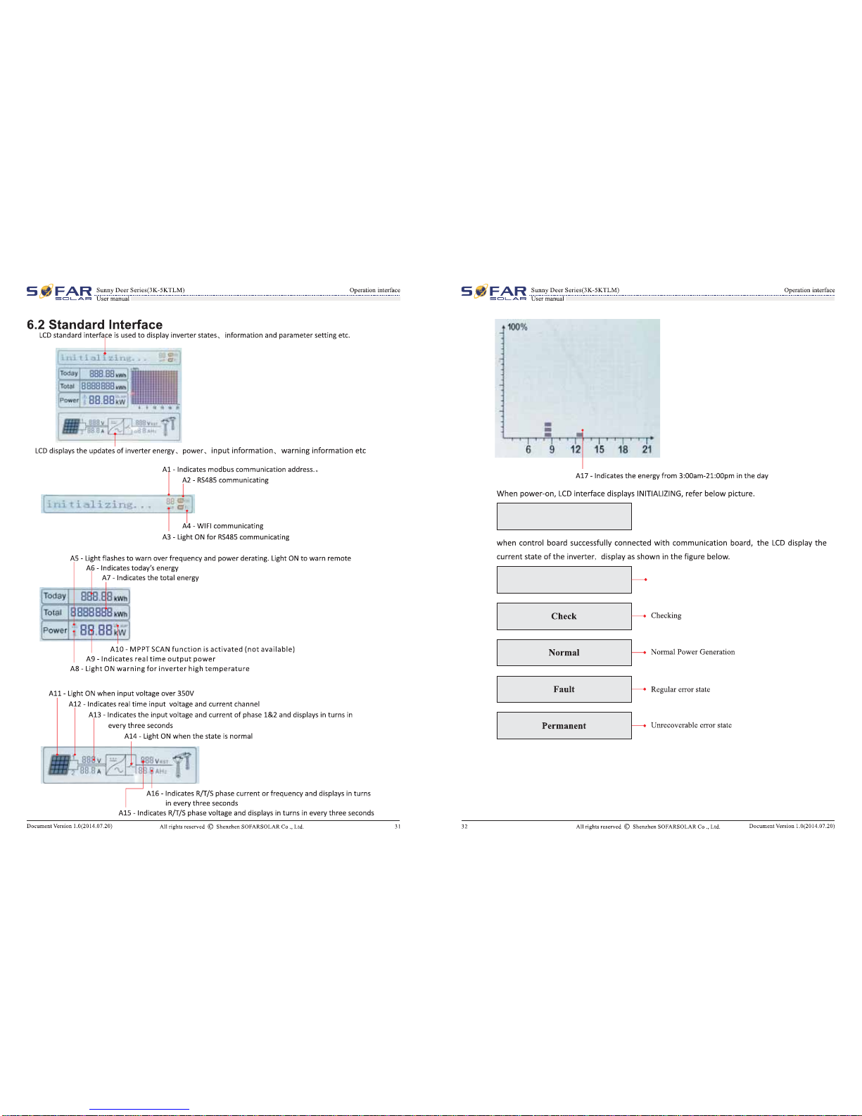
Inverter states includes:
wait~
chec~
normal~
fault and permanent
Wait : Inverter
is
waiting
to
Check
State at the end
of
reconnection time.
In
this state, the
PV
voltage
is
more than
250V,
grid voltage value
is
between the max
and
min limits
and
so
on;
If
not, Inverter will
go
to
Fault State
or
Permanent State.
Check: Inverter
is
checking isolation resistor,
relays,
and
other safety requirements.
It
also
does
self-test
to
ensure inverter software
and
hardware are functionaL Inverter will
go
to
Fault State or Permanent State
if
any
error
or
fault occurs.
Normal : Inverter enter
to
Normal State,
it
is
feeding power
to
the grid; inverter will
go
to
Fault State or Permanent state
if
any
error
or
fault occurs.
Fault : Fault State: Inverter
has
encountered recoverable error.
It
should recover
ifthe
errors
disappear.
If
Fault State continues;
please
check the inverter according error code.
Permanent : Inverter
has
encountered unrecoverable error, we need maintainer debug this
kind
of
error according
to
error code.
When the control board
and
communication board connection fails, the
LCD
display interface
as
shown in the figure below.
DSP communicate fail
6.3 Main Interface
Press
"Back" button under standard interface
to
enter into main interface, including:
I
Normal
f---
Press "Back"
1.
Enter
Setting
2.
EventList
3.
Systemlnfo
4. Display
Time
5.
Software
Update
DocumentVersion 1.0(2014.07.20)
All
rights reserved © Shenzhen SOFARSOLAR Co ., Ltd. 33
S
~
~
FAR
-
~~r.
.
'?.:~-'-
-
~
-
~.r.i
-
~.s.~~
-
~
-
:
~
-
~!
-
~~)
__________________________________________________________________________________________
?.P.~~~~
-
~
-
~~
-
~
sc::::::JLA.-===t
Usermanual
34
(A) "EnterSetting" Interface as below:
I
l.Enter
Setting
1. Set time
2.
ClearProduce
3. ClearEvents
4.
Set Country Code
5.
Remote Control
6.
Relay Command
7.
Enable Set Country
8.
Set Total Energy
9.
Set Mod-bus Address
10. Set Inputmode
11.
Set Language
12. Set
StartPara
13. Set SafetyVolt
14. Set SafetyFreq
15. Set Insulation
16. Relay Test
• SetTime
Users
press
"Back" button
to
enter
"l.Enter
Setting" interface,
Press
"OK" button
to
enter
main setting interface. Enter "1.
Set
Time"
by
pressing"Up" button or "Down" button, then
press"OK"button
and
start
to
set up time.
Time set from
year,
month,
day,
minutes,
and
seconds
in
turns, "Up" button
or
"Down"button
to
choose different value
to
set
each
date.
Set
each
value
is
need
to
press
"OK" button
to
confirm setting. "success"
is
displayed
if
the setting time
is
correct, "fail" means failure
settings.
All
rights reserved © Shenzhen SOFARSOLAR Co ., Ltd. DocumentVersion 1.0(2014.07.20)
This manual suits for next models
1
Other Sofar Inverter manuals

Sofar
Sofar GTX5000S User manual

Sofar
Sofar 3K-6KTLM User manual

Sofar
Sofar BTS E5-DS5 User manual

Sofar
Sofar 7.5KTLM User manual

Sofar
Sofar 255KTL-HV-TRO User manual

Sofar
Sofar HYD 6000-EP User manual

Sofar
Sofar DRM0 Reference manual

Sofar
Sofar 100KTLX-G4 User manual

Sofar
Sofar 25KTLX-G3 User manual

Sofar
Sofar ME 5KTL-3PH User manual

Sofar
Sofar HYD 5KTL-3PH User manual

Sofar
Sofar ME3000SP User manual

Sofar
Sofar HYD 5KTL-3PH User manual

Sofar
Sofar 25KTLX-G3 User manual

Sofar
Sofar HYD 5KTL-3PH User manual

Sofar
Sofar SOFAR 3K-6KTLM-G2 User manual

Sofar
Sofar CXAU0655BVS User manual

Sofar
Sofar HYD3000-ES User manual

Sofar
Sofar 125KTLX-G4 User manual

Sofar
Sofar HYD 3000-EP User manual


