Chziri ZVF9V-G/P User manual
User's Manualfor
ZVF9V-G/PVector Inverter
User's Manualfor
ZVF9V-G/PVector Inverter
Add.: 8 GandeRoad, Tahui,Shihudang Town,
Songjiang District, Shanghai201600, China
Tel.: 0086-021-57844525
Http://www.chziri.com
Manufacturer: Wenzhou Ziri Electrical
Technology Co.,Ltd.
Add.: Santiaoqiao IndustrialZone, Xiangyang
Town,YueqingCity 325604, Zhejiang,China
Tel: +86-577-27871155

Publication Notes
Ziri ElectricalTechnologyCo.,Ltd.
March 2009
All partsof theinverter ZVF9Vseries, including the
software, layout design,circuit boarddesign and
user s manualare reserved byZiri Electrical
TechnologyCo.,Ltd. (hereinafter referredto as"ZIRI
Company").Any unauthorized transfer, excerptsor
copying, inpart orin whole,is prohibitedor persecuted.
All thecontents inthis manual arefor reference only.
The software programand contents ofthe munualis
subject tochange orupgrade without priornotice.
Please browse ZIRIcompany s websitefor detailor
contact itdirectly.
If thereare anydoubts ormistakes inthis manual,ZIRI
Company claims immunityfrom them
Thank youvery muchfor yourpurchase ofthe inverter
ZVF9V series.
This manualintroduces theinstallation, operation,function
setting, troubleshooting andetc. ofthe inverterZVF9V
series..
Incorrect installationor usemay resultin damageor other
accidents. Doread allinstructions indetail beforeinstalling
or operating.
Please forwardthis manualto theend user,and keepit handy
for quickreference.
If thereare anydoubts orquestions, pleasecontact the
TechnicalService Centerof ZIRICompany.
Foreword

Tableof Contents
Tableof Contents
Table ofContents Table ofContents
Chapter 1 Safety Instruction ............................................ P1
1.1 Safety Symbols and Definitions ............................................P1
1.2 Application Range ................................................................ P2
1.3 Installation Ambient ..............................................................P2
1.4 Cautions for Installing............................................................P3
1.5 Cautions for Operation ........................................................P5
1.6 Cautions for Disposing ..........................................................P8
Chapter 2 Introduction to the Product.................................... P9
2.1 Product Inspection upon Arrival ........................................ P9
2.2 Demonstration of the Model ...................................................P9
2.3 Specifications Label ..............................................................P9
2.4 Outline and Structure ............................................................P9
2.5 Models and Specifications ...................................................P10
2.6 Technical Indications ............................................................P13
Chapter 3 Installing and Wiring ..........................................P18
3.1 InverterMounting andInstalling .............................................P18
3.2 Inverter Spare Parts Installing and Dismantling .....................P20
3.3 Inverter Wiring ...................................................................P25
3.4 InverterSystem Wiring ...........................................................P36
Chapter 4 Operation Panel and its Operation ........................P40
4.1 OperationPanel andthe Instruction ....................................... P40
4.2 Displayof MonitoringParameters ...........................................P47
4.3 Display of Trouble Parameters ............................................. P49
Chapter 5 Operation of the Inverter ...................................................P50
5.1 Trial Operation ................................................................................. P50
5.2 Cautions for Operation ..................................................................P52
5.3 Operation Examples .........................................................................P54
Chapter 6 Introduction to Function Parameters ........................... P61
6.1 Tables for Function Parameters ..................................................... P62
6.2 Detailed Instruction for Function Parameters ................................P80
Chapter 7 Common Problems, Anomalies and Troubleshooting ..P135
7.1 Diagnostic Trouble Codes and Troubleshooting ...........................P135
7.2 Anomalies and Solutions .................................................................P138
Chapter 8 Inverter Inspection and Maintenance ..............................P139
8.1 Inspection and Maintenance .........................................................P139
8.2 Replacement of the Inverter Wearing Parts ................................. P142
8.3 Storage of the Inverter ....................................................................... P143
Chapter 9Outline Dimensions& MountingDimensions ..................P144
9.1 InverterOutline Dimensions& MountingDimensions ........................P144
9.2 OperatorPanel OutlineDimensions &Mounting Dimensions.............P148
Chapter 10Quality Warranty ................................................................ P151
10.1 Inverter Quality Warranty ................................................................ P151
Appendices ............................................................................................P152
Appendix 1 Optional Parts Choosing .......................................................P152
Appendix 2 EMI Prevention .................................................................. P155
Appendix 3 User's Parameter Amendment Record ..............................P161
Appendix 4 Warranty ..............................................................................P164
Tableof Contents
Tableof Contents
Table ofContents Table ofContents
Chapter 1 Safety Instruction ............................................ P1
1.1 Safety Symbols and Definitions ............................................P1
1.2 Application Range ................................................................ P2
1.3 Installation Ambient ..............................................................P2
1.4 Cautions for Installing............................................................P3
1.5 Cautions for Operation ........................................................P5
1.6 Cautions for Disposing ..........................................................P8
Chapter 2 Introduction to the Product.................................... P9
2.1 Product Inspection upon Arrival ........................................ P9
2.2 Demonstration of the Model ...................................................P9
2.3 Specifications Label ..............................................................P9
2.4 Outline and Structure ............................................................P9
2.5 Models and Specifications ...................................................P10
2.6 Technical Indications ............................................................P13
Chapter 3 Installing and Wiring ..........................................P18
3.1 InverterMounting andInstalling .............................................P18
3.2 Inverter Spare Parts Installing and Dismantling .....................P20
3.3 Inverter Wiring ...................................................................P25
3.4 InverterSystem Wiring ...........................................................P36
Chapter 4 Operation Panel and its Operation ........................P40
4.1 OperationPanel andthe Instruction ....................................... P40
4.2 Displayof MonitoringParameters ...........................................P47
4.3 Display of Trouble Parameters ............................................. P49
Chapter 5 Operation of the Inverter ...................................................P50
5.1 Trial Operation ................................................................................. P50
5.2 Cautions for Operation ..................................................................P52
5.3 Operation Examples .........................................................................P54
Chapter 6 Introduction to Function Parameters ........................... P61
6.1 Tables for Function Parameters ..................................................... P62
6.2 Detailed Instruction for Function Parameters ................................P80
Chapter 7 Common Problems, Anomalies and Troubleshooting ..P135
7.1 Diagnostic Trouble Codes and Troubleshooting ...........................P135
7.2 Anomalies and Solutions .................................................................P138
Chapter 8 Inverter Inspection and Maintenance ..............................P139
8.1 Inspection and Maintenance .........................................................P139
8.2 Replacement of the Inverter Wearing Parts ................................. P142
8.3 Storage of the Inverter ....................................................................... P143
Chapter 9Outline Dimensions& MountingDimensions ..................P144
9.1 InverterOutline Dimensions& MountingDimensions ........................P144
9.2 OperatorPanel OutlineDimensions &Mounting Dimensions.............P148
Chapter 10Quality Warranty ................................................................ P151
10.1 Inverter Quality Warranty ................................................................ P151
Appendices ............................................................................................P152
Appendix 1 Optional Parts Choosing .......................................................P152
Appendix 2 EMI Prevention .................................................................. P155
Appendix 3 User's Parameter Amendment Record ..............................P161
Appendix 4 Warranty ..............................................................................P164
Chapter 1 Safety Instructions Chapter 1 Safety Instructions
Chapter 1 Safety Instructions
1.1 Safety Symbolsand Definitions
The safety instructionsdescribed in thismanual are veryimportant. To
avoid any errorthat may resultin damage toequipment, injury topersonnel
or loss ofproperty, doread and clearlyunderstand all ofthe safety symbols,
symbol definitions andbe sure toobserve the indicatedsafety instructions
below.
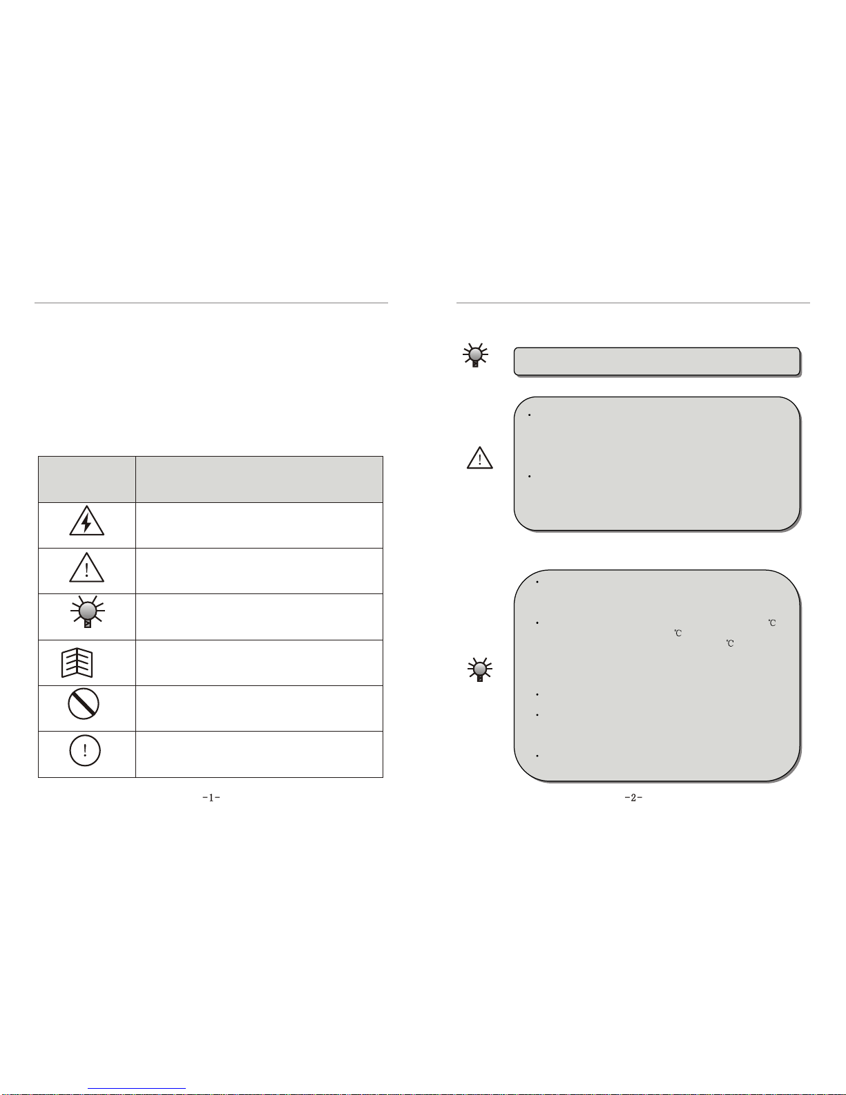
Safety Symbols Symbol Definitions
HAZARD
This symbol indicateshazardous HIGH VOLTAGE.
Any incorrect operationmay result inserious damage to
the equipment ordeath to personnel.
WARNING
CAUTION
TIP
FORBIDDEN
COMPULSORY
This symbol indicatesthat any incorrectoperation can
result in damageto the equipmentor minor tomoderate
injury to personnel.
This symbol callsyour attention tofollow the
instructions while inoperation or inuse.
This symbol callsattention to someuseful messages
for the user.
This symbol indicatesanything forbidden todo.
This symbol indicatessomething must do.
CAUTION
This inverter isapplicable to generalindustrial purpose three-
phase ACasynchronic electric motor.
1.2 ApplicationRange
WARNING
This inverter cannot be usedin the equipmentthat may result
in threat orinjury to personneldue to invertertrouble or error,
such as nuclearpower control equipment,aviation equipment,
transportation equipment, lifesupporting system, safety
equipment, weapon systemand etc. Pleaseconsult Ziri Company
before using itfor special purposes.
This product ismade under strictquality control and
supervision. But whenused in somekey equipment, protective
measures should betaken to avoidfurther extension ofaccident
due to invertertrouble.
1.3 InstallationAmbient
CAUTION
Be sure toinstall the inverterin a well-ventilatedindoor
location. To get thebest cooling effect, it isrecommended to
fix the invertervertically,and extra ventilationdevices are
needed when installedhorizontally.
Be sure thatthe ambient temperatureis between -10~45 .
If the temperatureis higher than40 , please removethe
upper cover.If the temperatureis higher than50 , forced
heat radiation orderating is neededfrom the external.It is
recommended not touse the inverterin such ahigh
temperature. Otherwise, it may greatlyreduce the servicelife
of the inverter.
The ambient humidityis required tobe lower than90%
without dew condensation.
The inverter shallbe installed ina place wherethe vibration
is less than0.5G. Otherwise, itmay fall andcause damage to
the equipment. Itis also noteworthythat the invertercould
not bear anysudden bump.
The inverter shouldbe kept awayfrom electromagnetic
interference (EMI), flammable and explosiveambient.
WARNING
Chapter 1 Safety Instructions Chapter 1 Safety Instructions
Be sure toinstall the inverteron metallic materials(i.e., metal).
Otherwise, there isthe danger offire.
Be sure notto let theforeign matter enterthe inverter,such as wire
clippings, spatter fromwelding, metal (zincor ferrous) meshavingsand etc.
Otherwise, there isthe danger ofgetting burned dueto short circuit.
1.4 Cautionsfor Installing
HAZARD
Do not operateelectrical equipment withwet hands.
Do not operatewiring unless thepower supply iscompletely
off.
Do not openthe front coveror perform wiringwhile the
inverter is poweredON. Otherwise, thereis the dangerof electric
shock.
Do wait atleast 10 minutesafter the poweris disconnected
before performing thework of wiringor inspection. Otherwise,
there is thedanger of electricshock.
WARNING
Do not installor operate ifthe inverter isdamaged or hasparts
missing to preventinjury to personnelor loss ofproperty.
The main loopterminal should betightly connected tothe cable.
Otherwise, the invertermay be damageddue to loosecontact.
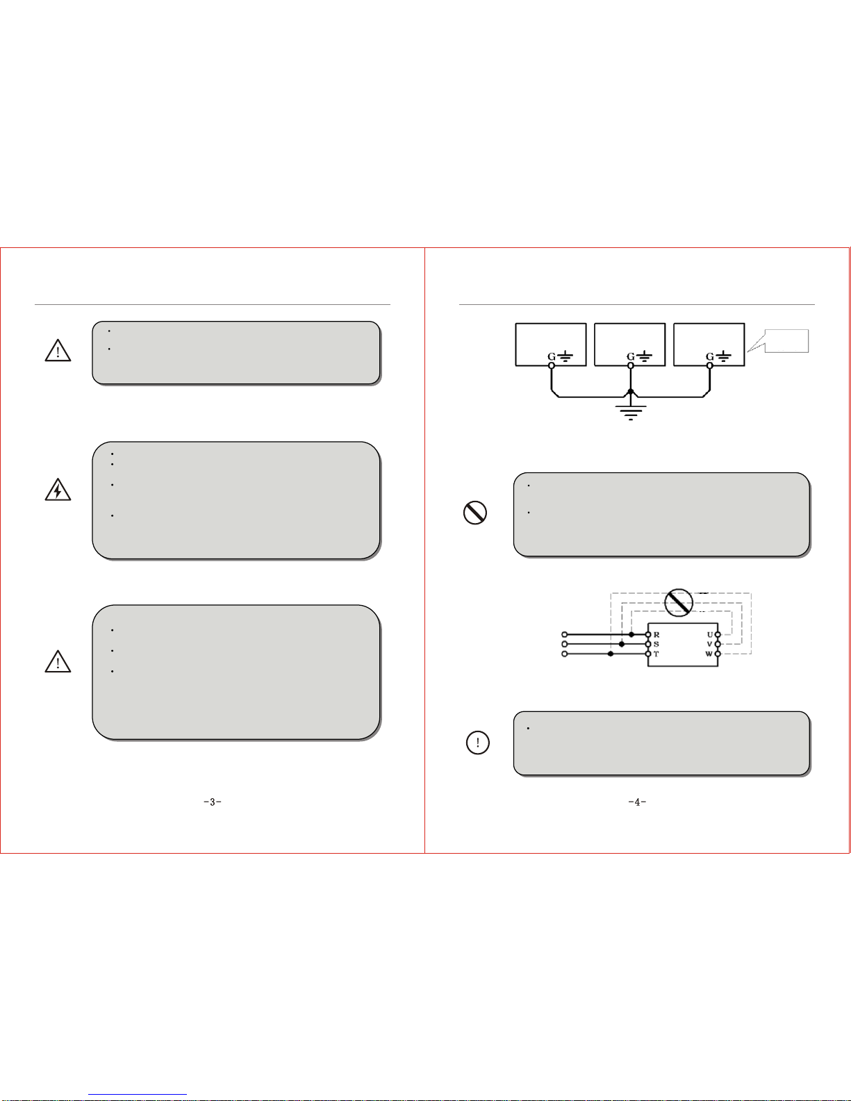
The ground terminalmust be reliablyand properly groundedto
ensure security.Toavoid common groundimpedance, multi-
piece inverters shouldbe grounded atone shared point,as shown
in the Figure1-1.
Inverter Inverter Inverter Proper
grounding
method
FORBIDDEN
Grounding bus bar
(Connect to theground at theshared point)
DO NOT connectcontrol terminals (exceptterminals marked"TA","TB"
and "TC") toAC 220Vpower supply,which may causedamage to theinverter.
DO NOT connectAC powersupply to theoutput terminals marked"U", "V"
and "W". Otherwise,it may causedamage to theinverter, as shownin the
Figure 1-2.
Three-phase
AC
Power Supply
FORBIDDEN
Figure 1-2
COMPULSORY
Figure 1-1
DO install ano-fuse circuit breakeror leakage protectivecircuit
breaker in theside of inverterinput power supplyto prevent
expanding of accidentdue to aninverter problem.

Chapter 1 Safety Instructions Chapter 1 Safety Instructions
CAUTION
It is notadvisable to installan electromagnetic contactorin the sideof
output power supply, because theoperation of openand close tothe
contactor when themotor is runningmay cause damageto the inverter
arising from over-voltageproduced during thisprocess. But itis still
necessary to installa contactor ifone of thefollowing three pointsoccurs:
1.The system offrequency converting governorused to controlenergy-
saving usually worksat a ratedrotation speed. To run thegovernor
economically, thereis a mustto remove theinverter.
2.The inverter participatesin some importprocedure and cannotstop
operating for along period oftime. Torealize free shiftin various control
systems and improvethe reliability ofthese systems, thereis a mustto
install a contactor.
3.When an invertercontrols several motors,there is amust to installa
contactor.
Caution: DO NOToperate the contactorif there isoutput of theinverter.
1.5 Cautionsfor Operation
HAZARD
Do not operateelectrical equipment withwet hands.
An inverter storedfor a yearor longer shouldbe given
powerup test beforeuse so thatthe main circuitfilter capacitor
could be recovered.When the inverter is inthe state ofpowerup,
it is necessaryto raise thevoltage gradually tothe rated value
with a voltageregulator. Generally, the chargingtime should be
controlled within 1~2hours. Otherwise, thereis the dangerof
electric shock orexposure.
Do not touchthe inner sideof the inverterwhile the poweris
ON, nor putany foreign matter, i.e., rodor other matterinside the
inverter. Otherwise,it may resultin serious damageto the
equipment or deathto personnel.
Do not openthe front coverwhile the inverteris powered ON.
Otherwise, there isthe danger ofelectric shock.
Be careful toselect the RestartMode. Otherwise, thereis
the danger ofpersonnel death.
WARNING
If the inverterruns at afrequency higher than50Hz, DO confirm
it is withinthe speed rangeacceptable by yourmotor bearing and
mechanical device. Otherwise, there isthe danger ofdamage to the
motor.
It is notadvisory to runthe reduction box,gear and other
mechanism that needlubricating at lowspeed for along period.
Otherwise, it mayreduce the servicelife of theseequipment or
even damage theequipment.
A generalmotor should bederated before usedue to less
effective ofheat dissipation whenit runs ata low frequency. If itis
a constant torqueload, then aforced method ora special variable
frequency motor shouldbe used torelease heat.
DO cut off the powersupply of aninverter set asidefor a long
time to avoidforeign matter orother things enterin it whichmay
cause damage tothe inverter oreven lead tofire.
The output voltageof inverter isPWM impulse wave.DO NOT
install a capacitoror surgecurrent sink (i.e.,a varistor) inthe
inverter output port.Otherwise, there isthe danger offault tripping
of the inverteror damage toits power elements.DO remove such
kind of thingsif already installed.See the Figure1-3 below.
Forbidden
Forbidden
Inverter
Power factor
compensation
capacitor
Surge current sink
Figure 1-3

Chapter 1 Safety InstructionsChapter 1 Safety Instructions
CAUTION
Motor insulation shouldbe checked beforethe inverter isused
for the firstuse or reusedafter a long-termidle. Be surethe
insulation resistance measuredis no lowerthan 5MÙ.
If the inverteris used beyondthe range ofallowable working
voltage, then anextra step-up orstep-down voltage transformer
shall be configured.
Due to thinair in aplace where thealtitude is higherthan
1,000m, the heatdissipation of inverterwill be lesseffective.
Hence derating shouldbe done beforeuse. In general,when the
height rises by1,000m, the ratedvoltage of theinverter shall
reduce by 10%.Refer to theFigure 1-4 fordetails of thederating
curve.
M
Figure 1-4 Diagramof Inverter DeratingCurve
FORBIDDEN
DO NOT touchthe radiator orcharging resistor ofthe inverter
with hand(s). Otherwise, thereis the possibilityof getting scalded.
DO NOT proceeddirect start-stop operation frequentlywith a
contactor or anyother switch devicesin the inverterinput side.As
large charging currentexists in themain circuit ofthe inverter,
frequent power-on/off mayproduce cumulative effectresulting in
heat fatigue ofinverter components and greatreduction of service
life of theinverter. Seethe detail inthe Figure 1-5.
Three-phaseAC PowerSupply
Inverter
Forbidden
On
Off
COMPULSORY
In case abnormalitiesoccur, such as smoke, offodor, strange
sound, DO cutoff the powersupply immediately,overhaul the
equipment or turn to the agent for help via phone call.
1.6 Cautionsfor Disposing
WARNING
CAUTION
Exposure may happenwhen the electrolyticcapacitor (ELCC)
of the inverterburns. Be carefulto cope withit.
The plastic partson the operatorpanel will giveoff toxic gas
when getting burned.Be careful tocope with it.
Dispose damaged inverteras industrial waste.

M: Integration Module
S: Schism Module

Chapter II Introduction tothe Product Chapter II Introduction tothe Product
Figure 2-5 ModelB Outside Drawing
1. Operator Panel 2. Control Panel 3. External ControlTerminal 4. Power Terminal
5. Lower Cover 6. Casing
Figure 2-6 ModelB Structural Representation
Figure 2-7 ModelC Outside Drawing
1.Fan 2. ControlPanel 3.Cabnet Body 4. WiringCopper Bar 5.PowerTerminal
6. Electrolytic Capacitor(ELCC) 7. OperatorPanel 8. CabinetDoor
Figure 2-8 ModelC Structural Representation
Chapter II Introduction tothe Product Chapter II Introduction tothe Product
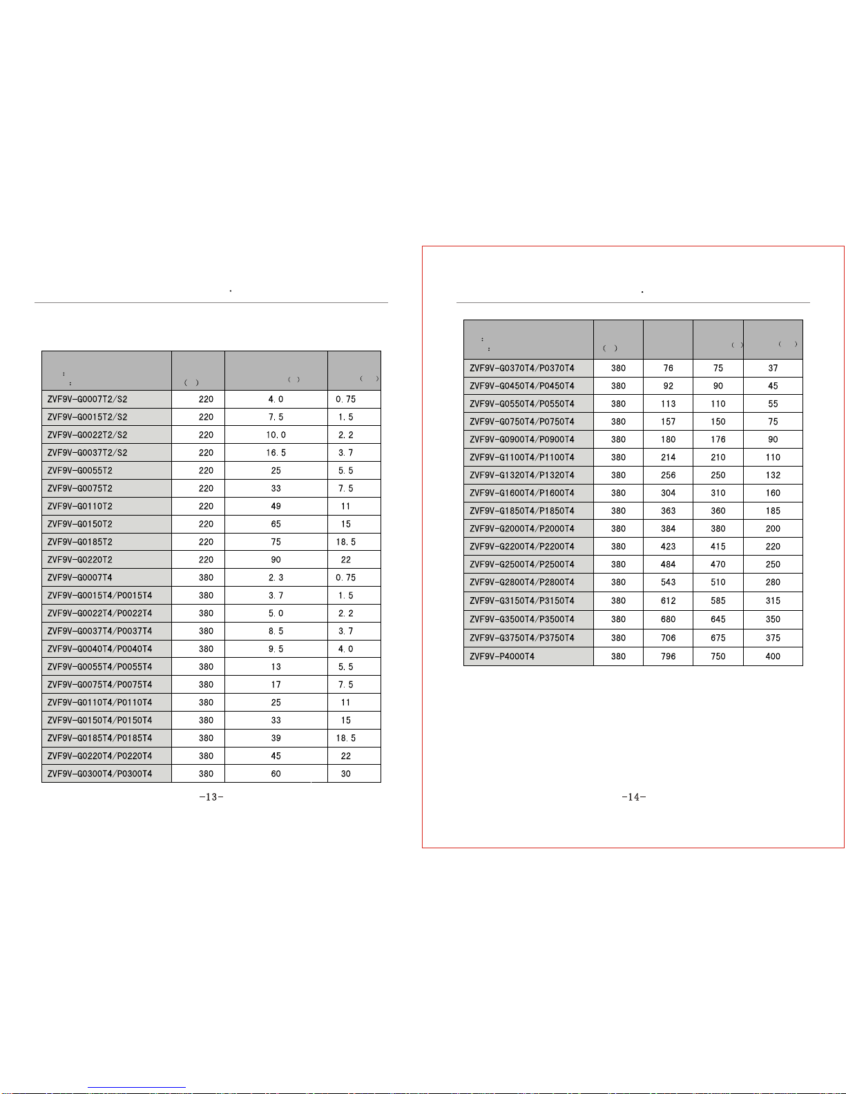
2.5 Models andSpecifications
Table 2-1Inverter Models andSpecifications
Inverter Models
(G Constant TorqueLoad)
(P Fan or PumpLoad)
Input
Voltage
V
Rated
Output
Current A
Adaptive
Motor
Power KW
Inverter Models
(G Constant TorqueLoad)
(P Fan or PumpLoad)
Input
Voltage
V
Rated
Output
Current A
Adaptive
Motor
Power KW
Rated
Input
Current (A)

Jog acceleration/deceleration
time, 0.1~3600.0 can beset.
current
Leap frequency,Jog function,counter,trace to rotatingspeed, instant
shutdown restarting, Frequecnyupper/lower limitation ,acceleration/
deceleration mode regulating,frequency meter andvoltmeter output,
multiple speed/program operation, two-wire/three wire control,
vibration frequency control,Multi-function input terminal selection,
Failure auto resetand 485COM.

Chapter 3Inverter Installationand Wiring Chapter 3Inverter Installationand Wiring
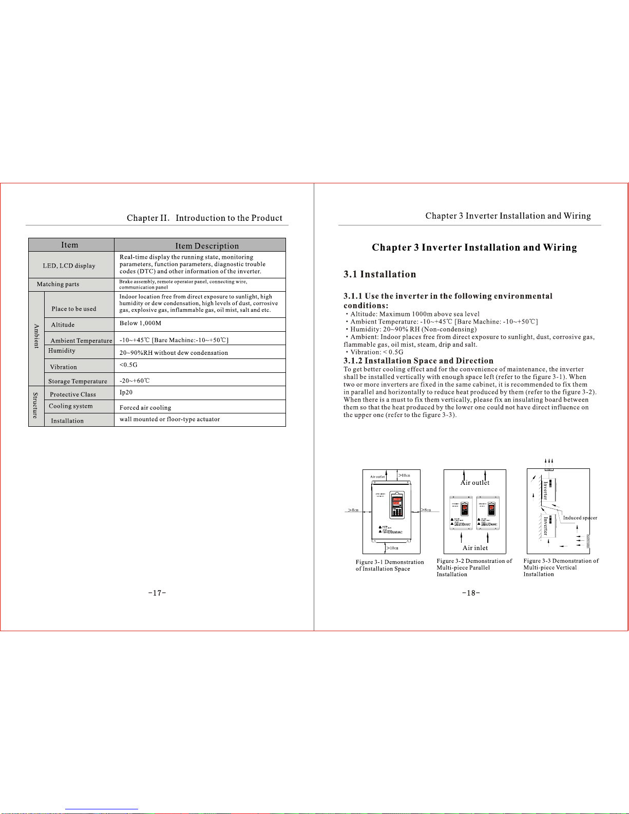
3.1.3 InstallationInstructions
WARNING!
Do not installor operate ifthe inverter isdamaged or hasparts
missing to preventinjury to personnelor loss ofproperty.
Be sure themain loop terminalsshould be tightlyconnected to
the cable. Otherwise,the inverter maybe damaged arisingfrom
loose connection.
Be sure theground terminals ofthe inverter andthe motor must
be properly grounded.Multi-piece inverter shouldbe grounded at
one shared point.
COMPULSORY!
Be sure toinstall a no-fusecircuit breaker orleakage protective
circuit breaker inthe side ofinverter input powersupply to
prevent expanding ofaccident due toan inverter problem.
CAUTION!
Install the inverterin a properplace with moderatetemperature. The
higher the ambienttemperature is, theshorter the servicelife of theinverter
is.Keep any otherheat-producing equipment asfar away fromthe inverter
as possible. Wheninstalling the inverterin an enclosure,maintain the
clearance around theinverter and verifythe temperature iswithin the
allowable range.
3.2 PartsDismantling andInstallation
3.2.1 Dismantle theupper cover.
1 Dismantle the uppercover of theinverter ModelA.
Put a fingerinto the heave of the lowerpart of theinverter and pressit (as shownin the
figure 3-4 wherethe arrow points),stretch forward for30~50mm (as shownin the
figure 3-5), thenraise upward toopen the uppercover of theinverter.
Fig. 3-4 Demonstrationof dismantling
the upper coverof the inverterModel A Fig. 3-5 Demonstrationof dismantling the
upper cover ofthe inverter ModelA
2 Dismantle the uppercover of theinverter Model B.
Unscrew two screwsof the lowerpart of theinverter (as shownin the figure3-6 where thearrow
points), pull thelower cover down for 10~20mm (asshown in thefigure 3-7), thenraise upward toopen the
lower cover ofthe inverter.
Fig. 3-6Demonstration of dismantlingthe
upper cover ofthe inverter ModelB
Fig. 3-7 Demonstrationof dismantling the
upper cover of the inverter Model B
Chapter 3Inverter Installationand Wiring
Chapter 3Inverter Installationand Wiring
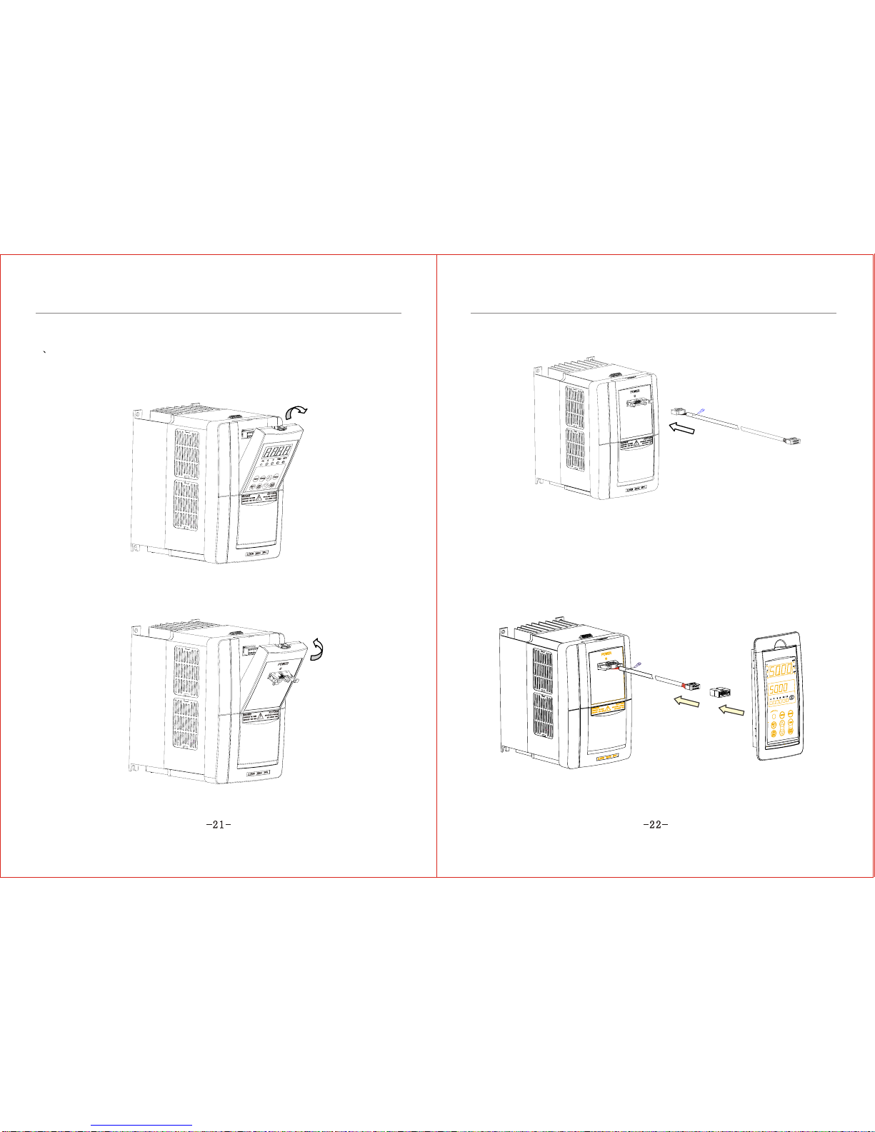
3.2.2 Installation ofthe remote-controlledoperator panel andconnecting wire
1 Installation of theoperator panel andconnecting wire ofthe inverter ModelA
Step 1. Buttonup with ahand at thenotch of the upperpart of operatorpanel and removethe
operator panel (asshown in thefigure 3-8).
Fig. 3-8 MountingDemonstration of theoperator panel
and connecting wireof the inverterModel A
Step 2. Fixthe jack panelprovided in theoptional components inthe installation positionof
operator panel (asshown in thefigure 3-9).
Fig. 3-9 MountingDemonstration of theoperator panel
and connecting wireof the inverterModel A
Step 3. Plugthe ground endof connecting wireprovided in theoptional components
into the slotof jack panel(as shown inthe figure 3-10).
Fig. 3-10 MountingDiagram for theoperator panel and
connecting wire ofthe inverter ModelA
Step 4. Putthe dismantled operatorpanel into theinstallation frame providedin the
optional components, fixand fasten it.Plug the otherend of connectingwire into the
jack panel slot,then plug theslot into theoperator panel (asshown in thefigure 3-11).
Fig. 3-11Mounting Diagram forthe operator panel
and connecting wireof the inverterModel A

Chapter 3Inverter Installationand Wiring
Chapter 3Inverter Installationand Wiring
2 Installation of theoperator panel andconnecting wire ofthe inverter ModelB
Step 1. Buttonup with ahand at thenotch of the upperpart of operatorpanel and removethe panel
(as shown inthe figure 3-12).
Fig. 3-12 MountingDiagram for theoperator panel and
connecting wire ofthe inverter Model
Step 2. Plugthe connecting wiresof the controlpanel and operatorpanel into thejack panel
provided in theoptional components, thenfix the jackpanel in theinstalling location of
operator panel (asshown in Figure3-13).
Fig. 3-13 MountingDiagram for theoperator panel and
connecting wire ofthe inverter ModelB
lug the groundingend of connectingwire into theslot of jackpanel (as shownin the
figure 3-14).
Step 4. Fixand fasten thedismantled operator panel, andput the otherend of connectingwire
into the socketof operator panel(as shown inthe figure 3-15).
Fig. 3-14 MountingDiagram for theoperator panel andconnecting
wire of theinverter Model B
Fig. 3-15 MountingDiagram for theoperator panel andconnecting
wire of theinverter Model B

Chapter 3Inverter Installationand Wiring Chapter 3Inverter Installationand Wiring
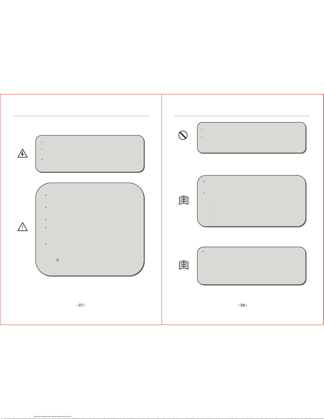
3.3.2 Cautions forWiring
Hazard!
Wait atleast 10 minutesafter power OFFbefore opening the frontcover
of the inverter.
Verifythe charge indicatorlamp is OFFbefore proceeding thework,
and be surethat the voltagevalue of themain loop terminalP and DCis
less than 36VDC.
The internal wiringof the invertershould be operatedonly by
authorized qualified personnel.
WARNING!
Verifythe rated inputvoltage of theinverter is matched
with ACpower supply. Otherwise, thereis the possibilityof
damage to theinverter.
Install in orderand only operatewiring after finishing
main parts installation.Otherwise, there isan electric
shock or damageto the inverter.
Do not performover-voltage withstandto the inverter,
for this hadbeen done properlybefore EX-factory.
Be sure toinstall a non-fusecircuit breaker inthe input
power supply sideof the inverterto prevent expanding of
accident due toan inverter problem,which may cause
damage to thedistribution equipment orlead to fire.
Be sure toconnect the groundterminal and themotor
casing to theground wire whichmust be coppercore. The
diameter of thecopper core shouldconform to therelevant
national standard.The ground resistanceshould be less
than 10 .
FORBIDDEN!
DO NOT connectAC powersupply to theoutput terminals marked
"U", "V" and"W". Otherwise, therewill be damageto the inverter.
DO NOT connectcontrol terminals (exceptterminals marked
"TA","TB" and "TC")to AC220V power supply, which maycause
damage to theinverter.
When the open-ended output terminal of thecollector
connects to anyinductive load, i.e., the relaycoil, do inserta
diode at eachend of theload in parallel.
The control wirein the inverteror the controlcabinet should
be at least100mm away fromthe power cable.DO NOTput
them in thesame metallic channel. If thesignal wire andthe
power cable needto intersect, theyshould intersect atan angle
of 90 . The control wire mustadopt STP(shielded twisted pair
wire); the shielded layer mustconnect to theterminal GND;
and the powerwire is recommended to usemetallic shielded
cable
The unavoidable strongelectromagnetic interference ofthe
inverter may havebad influence onall the electricalequipment
and meters inthe same environment.Toreduce interference, the
output cable ofthe inverter canbe inserted inthe metal pipe
connecting to theground or inthe metallic shieldedcable, and
connect the metallicshielded layer tothe ground. Inaddition, a
magnetic loop puton the outputcable is alsoeffective to reduce
interference.
Tips
Tips

Chapter 3Inverter Installationand Wiring Chapter 3Inverter Installationand Wiring
3.3.3 Instruction onMain CircuitTerminals
1 The main circuitterminals are shownas in thefigure 3-18~3-23.
Connect to
ground
Connect to
ground
Single-phase
220V power
supply input
Connect to
braking
resistance
Connect to
braking
resistance
Connect to
three-phase
AC motor
Connect to
three-phase
AC motor
Fig.3-18 Diagram 1for Main CircuitTerminals
Applicable
to Model
Applicable
to Model
Three-phase 380V
(or three-phase 220V)
power supply input
Connect
to ground
Three-phase 380V
power supply input
Braking
resistance
Braking unit Connect to
three-phase
AC motor
Fig.3-20 Diagram 3forMain Circuit Terminals
Applicable
to Model
Applicable
to Model
Three-phase
380V input
power supply
Connect
to reactor
Connect to
braking unit Connect to
three-phase
AC motor
Connect to
ground
Fig.3-19 Diagram 2for Main CircuitTerminals Fig.3-21 Diagram 4for Main CircuitTerminals

Chapter 3Inverter Installationand Wiring Chapter 3Inverter Installationand Wiring
Three-phase
380V input
power supply
Three-phase
380V input
power supply
Connect to
braking unit
Connect to
braking unit Connect to three-
phase AC motor
Connect to three-
phase AC motor
Connect
to ground
Connect
to ground
Fig.3-22 Diagram 5for Main Circuit Terminals
Applicable
to Model
Applicable
to Model
2 Function Description Main CircuitTerminalson
Terminal Symbols Function Description
Power supply input terminalsconnecting to three-phase 380Vor 220V ACinput
power supply
Power supply input terminalsconnecting to single-phase 220VAC input powersupply
Inverter output terminalsconnecting to three-phaseAC motor
External braking resistance terminalsconnecting to both endsof the external
braking resistance
External braking unit terminals;terminal P connectsto the positive endof the
braking unit and DC-connects to the negativeend.
External AC reactorterminals connecting to bothends of theAC reactor
Ground terminal connecting tothe ground
Tips
The three-phase inputpower supply terminals(R, S andT)
do not differ on phasesequence and canbe connected
arbitrarily.
If the motorcounter rotates (reverses)when the output
terminals U,V andW connectto three-phase motor, just
exchange two phasesof U, Vand Warbitrarily.
A brakingunit is requiredto be installedinside the inverter
under 15KW. If anexternal braking resistance is required,just
connect to theexternal braking resistancebetween terminal P
and terminal DB.
An inverter higherthan 18.5KWhas no internalbraking
unit, so ithas no DBterminal. If abraking torque isneeded,
please connect tothe external brakeassembly including
braking unit andbraking resistance between Pand DC-.
ZVF9V-G1600T4/P1850T4or even updatedmodel is
matched with DCreactor. Ifan inverter hasno internal DC
reactor, justfix a DCreactor between Pand DC+.When
performing this step,it is requiredto remove theshort-circuit
ring, then connectto the reactor(applicable to theinverter of
18.5KW orhigher power).
Fig.3-23 Diagram 6for Main CircuitTerminals

Chapter 3Inverter Installationand Wiring Chapter 3Inverter Installationand Wiring
3.3.4 Description onControl CircuitTerminals
1 Control circuit terminalsare shown inthe figure 3-24and 3-25
Fig.3-24 Control CircuitTerminals(1)
Fig.3-25 Control CircuitTerminals(2)
2 Description on ControlCircuit Terminals
Table 3-2Function Description onControl CircuitTerminals
Types Terminal
Symbols Function Description Electrical Specifications
Public
Port Digital signal publicterminal
Forward when FWD-COM shortcuts,
decelerate and stop whenFWD-
COM is open.
Running
Control
Terminal Reverse when FWD-COM shortcuts,
decelerate and stop whenFWD-COM
is open.
INPUT, 0~24 power level,
low level valid,5mA
Multi-function Input
Terminal
Validonly when there isa short
circuit between Xn (n=1,2, 3, 4,
5, 6) andCOM. The functions
can be setby the parameter
F4.00~F4.05 separately.
INPUT, 0~24 power
level, low levelvalid,
5mA
Multi-function
OutputTerminal
Multi-function open-
collector output isdefined as
on-off output terminal,whose
function is setby the
parameter F4.07~F4.08 with
reference of COM.
OUTPUT, MaximumCurrent
Load
Ground Terminal
VacantTerminal
Others
Table of contents
Other Chziri Inverter manuals


