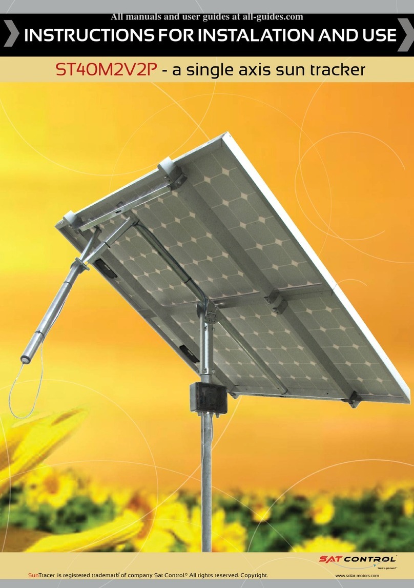
Solbian SL80 User manual

INSTALLATION MANUAL
Solar Panel Models:
SL40L – SL40Q
SP50L – SP50Q
SL80
SP 00
SP112
SP125
CP125
SP137
CP140

. INTRODUCTION
2. SAFETY
Warnings and electrical risks
3. SOLBIANFLEX Solar Panels
Packing contents
Technical data
Accessories
4. INSTALLATION
Installation advice
Panel installation
Electric connections
5. MAINTENANCE
SUMMARY

CongratulationV RQ the choice youKDYH made LQbuying thLV
SOLBIANFLEX SDQHOfor PDULQH use. ,WKDVEHHQPDQXIDFWXUHG
ith the most innovative technologies and ithWKH highHVW quality
components.

INTRODUCTION
$6RODU3DQHO installation can be DFFRPSOLVKHG by DQ\FRPSHWHQWSHUVRQ ith VLPSOHWRROV. +RZHYHU
WKHLQVWDOOHU takes responsibility for DOO accidentV WKDWPD\RFFXU during the installation, including electric shocks
THE FOLLOWING INSTRUCTIONS ARE ONLY A GUIDEWE +,*+/<RECOMMEND 7+$7<28 &2168/7$
0$5,1((/(&75,&$/,167$//(5,)<28+$9($1<48(67,2165(*$5',1*<285,167$//7,21
www.solbian.eu
WARNINGS
These instructions must be carefully read and understood before proceeding with Solar Panel
installation, connection, utili ation and maintenance. Touching the electrically active parts of the panel, like
terminals, may cause burning, sparks or low voltage discharges, even when the panel is disconnected.
A Solar Panel produces electricity when the front part is exposed to sunlight or to another light
source. Even if the voltage produced by a single panel is not dangerous for health, when the panels are
connected in series, voltages add up, and when they are parallel connected, currents are additive. So a system
with more than one panel can produce a high voltage or high currents that can be dangerous and can cause
injuries or death.

2
SAFETY
WARNINGS AND ELECTRICAL RISKS
Before installing the panel verify the need of permission or licenses that may be requested by the
law.
If not specified, it is recommended that you follow the newer national and international laws.
A bad installation can cause problems to the entire electrical system. Additional
devices such as groundings, fuses, diodes, charger or power disconnector switch may be required.
Do not use different types of panels on the same system.
Avoid electrical risks during the installation, connection, utili ation and maintenance.
A Solar Panel produces continuous current when exposed to sunlight or other light
sources. During the panel installation or connection, it’s highly recommended to completely cover
the front part of the panel with a soft, light-inhibiting material to avoid electricity production.
The panel must stay in his original packaging until the moment of installation. Never touch
terminals when the panel is exposed to light or during the installation. Use insulating gloves to
avoid contact with the terminals. As a further precaution, use only properly isolated tools.
Do not subject the panel to damage by unnecessarily rough treatment, or by dropping objects on it.
Ensure that the system parts can’t cause mechanical or electrical damage.
Do not install the panel in the presence of inflammable gasses or steam, as sparks are always possible.
Do not install or use a damaged panel.
Installation must be accomplished only by qualified persons. Do not allow children to touch the panel.
.
Use the panel only for it's intended purpose. Follow all the manufacturers instructions. Do not
disassemble or remove any part or label installed by the manufacturer.
Do not put any paint or labels on the panel.
Never focus sunlight on the panel.
Preserve these instructions for future reference.

3
SOLBIANFLEX SOLAR PANELS
PACKAGING CONTENTS
The Packaging includes:
TECHNICAL DATA
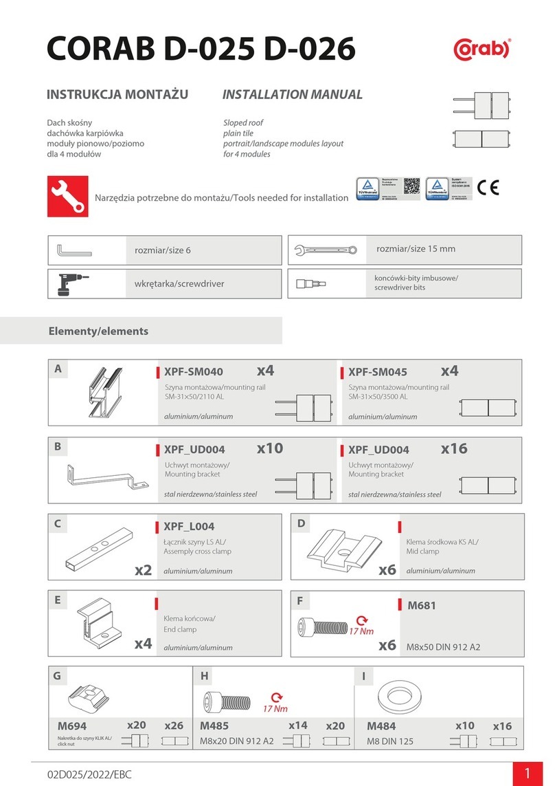
SOLBIANFLEX Solar Panels utilize mono-crystalline silicon cells with high efficiency to convert
energy from sunlight into electricity. The circuit of the cell assembly is laminated to a polymer formed by a
sheet of transparent plastic in front, and an opaque plastic sheet on the back, which serves as protection
against weathering and provides electrical insulation.
ACCESSORIES
One or more SOLBIANFLEX SP, SL or CP panels.
Installation Instructions.
Two pairs of heat-shrink tubing for the Rear Wiring Strips, for each panel supplied with that option.
One pair of MC4 connectors for each panel supplied with Quick Connect Cables, if no Cable set purchased .
Charge Regulators
Required to be able to safely connect your Solar Panel to a battery.
We highly recommend Genasun controllers with MPPT technology.
Solbian 40watt and 50watt panels have an 8v nominal output and
must use a Genasun Boost controller for connection to 12v systems.
All Genasun controllers are available from your Solbian dealer.
Cables
Various lengths are available from your Solbian dealer.
MC4 connectors
If your Solbian Solar Panel is supplied with the Quick Connect Cable
option and a Cable is not purchased with the panel, a pair of MC 4
connectors is supplied to be able to connect the panel to a controller.
Extra sets of MC4 connectors are available from your Solbian dealer.

4
SL40L SL40Q
11.5"
43.7"
21.6"
23.4"

5
SP50L SL50Q
11.5"
43.7"
21.6"
23.4"

6
SL80L SP 00L
21.6"
43.7"
21.6"
43.7"

FIXING: DOUBLE SIDED TAPE
SOLBIANFLEX PANELS series CP are made with a
special adhesive that allows, thanks to their exibility, easy
installation even on surfaces not totally at.
On request we can supply the complete kit for installation:
Photovoltaic Panel
Charhe regulator
Connectors (pairs)
Cable (4 m)
SOLBIAN.EU
DATA SHEET
SOLBIAN ENERGIE ALTERNATIVE SRL
Legal and Operative Headquarter: Via Caselette, km.16.200 - 10091 Alpignano (TO) - Phone: +39 011.966.35.12 - Fax: +39 011.966.47.20 - [email protected]
Ofce in Avigliana: Viale dei Mareschi, 15 - 10051 Avigliana (TO) - ITALY - Phone: +39 011.932.56.66 - Fax: +39 011.932.56.64 - [email protected]
FLEX CP125
Lenght
PHYSICAL CHARACTERISTICS
ELECTRICAL CHARACTERISTICS
Height
Thickness
Weight
Vp max
Ip max
Wp
Vca
Icc
Efciency (module)
Max Bending
1380 mm
680 mm
1,5 mm
2,35 kg
16,86 V
7,61 A
128,40 W
20,10 V
8,10 I
14,44%
25%
P
P
P
P
CONNECTION: JUNCTION BOX
CONNECTION AND FIXING OPTIONS
INSTALLATION
54.3"
26.8"
54.3"
26.8"
1/16"
5.2 lb
For best results, use the Genasun GV-10
MPPT Controller. One per panel.

SOLBIAN.EU
FLEX SP125
CURVE I-V
FIXING: STAINLESS STEEL EYELETS
FIXING: DOUBLE SIDED TAPE
CONNECTION: JUNCTION BOX
CONNECTION: SOLDERING RIBBON
CONNECTION AND FIXING OPTIONS
ELECTRICAL CHARACTERISTICS
Peak Power (+/- 5%) - Pmax
Rated Voltage - Vmp
Rated Current - Imp
Open Circuit Voltage - Voc
Short circuit Current - Isc
Temp. coeff. Pmax
Temp. coeff. Voc
Temp. coeff. Isc
Lenght
Width
Thickness
Weight
Num. of cells
128 W
22.5 V
5.7 A
26.9 V
6 A
-0.38%/°C
-0.27%/°C
0.05%/°C
1372 mm
550 mm
2 mm
1.8 kg
40
PHYSICAL CHARACTERISTICS
Current [A]
Voltage [V]
1.0
0.0
0 2.5 5 7.5 10 12.5 15 17.5 20 22.5
2.0
3.0
4.0
5.0
6.0
7.0
SOLBIAN ENERGIE ALTERNATIVE SRL
Legal and Operative Headquarter: Viale Gandhi 21b - 10051 Avigliana (TO) - ITALY
!
!
WARRANTIES
5 year limited power warranty
2 year limited product warranty
Current/voltage characteristics with dependence on irradiance and module
temperature.
1000 W/m2at 50º C
1000 W/m2
800 W/m2
500 W/m2
200 W/m2
FIXING: ZIPPER
54.0"
21.6"

SOLBIAN.EU
FLEX SP137
CURVE I-V
FIXING: STAINLESS STEEL EYELETS
FIXING: DOUBLE SIDED TAPE
CONNECTION: JUNCTION BOX
CONNECTION: SOLDERING RIBBON
CONNECTION AND FIXING OPTIONS
ELECTRICAL CHARACTERISTICS
Peak Power (+/- 5%) - Pmax
Rated Voltage - Vmp
Rated Current - Imp
Open Circuit Voltage - Voc
Short circuit Current - Isc
Temp. coeff. Pmax
Temp. coeff. Voc
Temp. coeff. Isc
Lenght
Width
Thickness
Weight
Num. of cells
137 W
24.0 V
5.7 A
29.1 V
6 A
-0.38%/°C
-0.27%/°C
0.05%/°C
1499 mm
550 mm
2 mm
2 kg
44
PHYSICAL CHARACTERISTICS
Current [A]
Voltage [V]
1.0
0.0
0 2.5 5 7.5 10 12.5 15 17.5 20 22.5
2.0
3.0
4.0
5.0
6.0
7.0
SOLBIAN ENERGIE ALTERNATIVE SRL
Legal and Operative Headquarter: Viale Gandhi 21b - 10051 Avigliana (TO) - ITALY
!
!
WARRANTIES
5 year limited power warranty
2 year limited product warranty
Current/voltage characteristics with dependence on irradiance and module
temperature.
1000 W/m2at 50º C
1000 W/m2
800 W/m2
500 W/m2
200 W/m2
FIXING: ZIPPER
59.0"
21.6"

7
INSTALLATION
There are multiple ways of installing Solbian Solar Panels. The panels can be supplied with
either Quick Connect Cables or Rear Wiring Strips for the electrical connection, and Velcro,
zippers, grommets and other custom fasteners can be installed by your local canvas shop.
Installing a Solbian Solar Panel with Terminal Strips permanently to a hard surface requires
special considerations. It is recommended that this type of installation be accomplished by
a qualified and competent professional. The use of a twin-wall backing panel is highly
recommended for this type of installation.
Solbian Panels must not be bent to a chord height (sagitta) greater than 25% of the arc length.
Simplified: The depth of bend must not exceed 25% of the length or width of the panel.
Panels must be properly installed, following the instructions. The support structure that the panel will be
installed on, must be capable of full support, without deformation, in any weather condition, like wind, snow
and, for marine applications, salt and storms. The support structure should not be subjected to excessive bending
and flexing. Excessive and repetitive flexing or bending of the support structure may cause irreversible damage to
the panel components, reducing the efficiency and possibly causing internal structural damage.
S
Modules fixing must be executed with maximum attention and precision, in fact the glue placed on
SOLBIANFLEX modules doesn’t permit a replacement or a splitting up of modules without damaging it. First
of all, put the sheaths that shrink when exposed to heat into ribbons, paying attention to put the sheath
s as
nearest as possible to the module. The aim is to minimi e the surface covered by ribbons. Use a hot source
(phon or flame) to shrink and then adhere the sheaths to ribbons. Eventually use some SikaFlex to
electrically isolate with a thin coating the metallic part of the ribbon nearest to the module that could be
uncovered by sheaths. Sign a rectangle on the rigid support where the module will be fixed on, with the
same internal dimension of the module, to determine its exact position:
The mounting of the panel must permit air to freely circulate at least on the face exposed to sunlight.
This reduces the temperature and results in better performance.
Electrical wiring size must be sufficient for a maximum voltage drop of 3%. Consult NEC tables, ABYC
Standard E11, or your Solbian dealer for guidance.
It is recommended to use electrical cable designed for the marine environment if permanently exposed.
Purpose made electrical cables with MC4 connectors are available from your Solbian dealer .
IMPORTANT:
.
IF THE PANEL IS TO BE MOUNTED ON A FLEXIBLE SURFACE, I.E. A CANVAS DODGER OR
BIMINI, THERE MUST BE NO COMPONENT OF THE SUPPORT STRUCTURE UNDER THE
MATERIAL THAT CAN INTERFERE WITH THE UNIFORM LAY OF THE PANEL.
.
THERE MUST BE NO BEAM, RAIL, BAR, OR OTHER FORM OF BRACING OR SUPPORT
UNDER THE CANVAS OR FLEXIBLE MATERIAL THAT CAN FORM A HARD RIDGE THAT THE
PANEL MIGHT REST ON. THE PANEL MUST LAY ON COMPLETELY UNSUPPORTED
MATERIAL FOR THE ENTIRE PANEL SURFACE AREA.
.
FAILURE TO FOLLOW THESE INSTRUCTIONS WILL RESULT IN DAMAGE TO THE PANEL
AND FABRIC THAT WILL NOT BE COVERED UNDER WARRANTY.

8
When installing a Solbian Solar Panel with Rear Wiring Strips permanently to a rigid structure like a cabin top or
hard top on a bimini, etc., it is suggested to first mark the position with masking tape or a temporary frame. Then
make a cardboard copy of the panel with holes cut where the wires connected to the wiring strips will exit.
.
Lay the cardboard within the frame or tape and mark the holes for the wiring. Drill large enough holes so that short
lengths of hose can be glued in place as a means of protecting the structure and wiring, and these can be filled with
sealant after the panel is installed and the wiring has been soldered to the wiring ribbons and protected with
heat-shrink tubing. Use a high-quality marine adhesive to secure the panel to the structure, and ensure that it is
compatible with the material of the structure and that it can withstand constant exposure to harsh environments.

9
ELECTRICAL CONNECTIONS
There are several possible ways to connect multiple SOLBIAN Solar Panels to the batteries, either individually
or by wiring them in series or paralell and sharing a common controller. However, it is not recommended to connect
Solar Panels in marine applications in series.
Wherever possible, it is highly recommended that each Solar Panel has its own dedicated MPPT controller. This
will ensure the maximum performance possible even if one panel becomes compromised by partial shading.
If two or more panels are wired in parallel, blocking diodes should be installed in the positive lead of each panel.
Selecting combinations of series/parallel and choice of regulators
SOLBIANFLEX Solar Panels can be connected to each other and to the batteries in parallel, in
series or in mixed series-parallel combinations. A solar controller of some type must always be used to ensure
that the batteries receive the correct charging voltage and so are not subjected to dangerously high voltages.
Simple volt-dropping controllers waste a lot of the Solar Panel's potential output and cannot compensate for
the losses from shading. Good quality Maximum Power Point Tracking (MPPT) controllers, like those from
Genasun, can give 30% more power and up to 50% better results in partially shaded conditions.
Ideally, each Solar Panel should have its own dedicated MPPT controller, as in Figure 1 below. This will ensure
the maximum possible charging current when one or more panel is shaded.
If panels are connected in parallel, as in Figure 2, and then "share" a controller, a shaded panel(s) will seriously
compromise the output of the unshaded one(s). If panels must be connected in parallel, a Blocking Diode must be
installed in the positive lead from each panel.
For 24v systems it is recommended that each Solar Panel has it's own dedicated Genasun GVB 24-8 Boost
controller, as shown in Figure 3. It is not recommended to wire the Solar Panels in series, as in Figure 4.

0
Solban 40 watt and 50 watt Solar Panels have an
8v nominal output, and so a special boost controller
must be used to boost this to charge a 12v battery.
Use the Genasun GVB 12-8 Boost controller on
40 watt and 50 watt panels. Best results are gained
from installing one controller per panel, paralleling
their outputs to the battery.

Two or more panels can be connected in parallel to one controller as
long as the controller is rated to take the combined output. Blocking
diodes must be installed in the positive lead of each panel, as shown.
NOTE: In this configuration, if one panel output is reduced by shading, it
will compromise the output of the other panel also. Ideally, each panel
should have it's own independent controller, as in figure 1.
For 80 watt and 100 watt panels, use the Genasun GV-10 controller.

2
When installing Solbian Solar Panels on a 24v
system, use Genasun GVB 24-8 Boost controllers.
Best results are obtained with one controller per
panel and their outputs paralleled to the battery.
(Figure 4)
8 volt
12 volt

3
This configuration is not recommended. Use 2 x Genasun GVB 24-8
Boost controllers as shown in Figure 3

4
MAINTENANCE
Solar Panels do not require excessive maintenance, thanks to the absence of
mechanical parts. Maintenance can be reduced to these simple procedures:
POSSIBLE BREAKDOWNS
Failures of Solbian Solar Panels are rare due to the stringent quality controls that each panel is
subjected to before being released for sale. The following are among the possible causes of failure unrelated
to the manufacturing process:
Keep the panel clean. In a marine environment, wash the panel often with fresh water to avoid
salt build-and reduce the possibility of damage;
Check the panel often for signs of delamination, or problems with mounting or securing;
Check electrical connections and wires periodically;
Check the system occasionally for electrical efficiency and signs of deteriating output.
Cells breaking due to excessive bending of the panel;
Cells breaking due to mechanical stress or physical abuse of the panel;
Cells breaking due to defective installation of a panel on a solid surface. (i.e. the presence of air
bubbles between a panel and the solid surface may cause damage).
Water infiltration and entrapment between the panel and a solid surface.
The ingress of water into the Junction-Box.
This manual suits for next models
10
Table of contents
Other Solbian Solar Panel manuals
