Sole Diesel 14 GSC User manual
U_ GBAV_EN, U_GBMV_EN, U_ GBBA_EN, U_GBNA_EN, U_ GCAS_EN, U_GCMS_EN,
U_ GCAW_EN, U_GCMW_EN, U_ GDAT_EN, U_GDMT_EN, U_ GDAX_EN, U_GDMX_EN
Rev. 3

1
Rev. 3

2
Introduction
Presentation
Dear Customer,
First of all, we would like to thank you for choosing a Solé Diesel product. We recommend that
you read this manual carefully before carrying out any of the operations and keep it close at hand, near
the genset, as it can be of great use in the future.
Our goal as a manufacturing company is that you enjoy our product, regardless of the use you
make of it. The equipment manufactured in Solé Diesel facilities is designed to offer the highest
performance in the most demanding operating conditions.
NOTICE
The images, text and information contained in this manual are based on the product’s features at the time
of publication. Solé Diesel reserves the right to modify this document without prior notice.
Abbreviations
BTDC: Before Top Dead Center
ATDC: After Top Dead Center
BBDC: Before Bottom Dead Center
ABDC: After Bottom Dead Center
API: American Petroleum Institute
ACEA: European Automobile Manufacturers’ Association
ASTM: American Society for Testing Materials
TBD: To Be Determined
Units of measurement
Measurements are based on the International System of Units (SI), and their converted metric
values are indicated in parentheses (). For metric conversion, the following rates are used:
-Pressure: 1 Pa = 1,0197 · 10-5 kgf/cm2= 1 · 10-5 bar
-Torque: 1 Nm = 0,10197 kgf·m
-Force: 1 N = 0,10197 kgf
-Power: 1 W = 1,341 · 10-3 HP

3
Rev. 3
TABLE OF CONTENTS
Introduction 2
Safety Precautions and Instructions 7
Service Assistance 11
Section 1 Genset Information 12
1.1 Genset Identification 12
1.2 Technical Specifications 13
1.3 Genset Limited Warranty 17
Restrictions 17
After-sales Service Contact 18
Section 2 Transport, Handling and Storage 19
2.1 Receipt 19
2.2 Transporting and Handling the Packed Genset 19
2.3 Transporting and Handling the Unpacked Genset 20
2.4 Storage of Packed and Unpacked Genset 21
Section 3 Installation 22
3.1 Angular Operation 22
3.2 Genset Installation 22
3.3 Prestart Checklist 23
Section 4 Operation 24
4.1 Starting Genset 24
4.2 Stopping Genset 24
4.3 Genset Operation at Low Temperatures 25
4.4 Winterization and Preservation 25
4.5 Restoration of Operational conditions 26
Section 5 Systems and Scheduled Maintenance 27
5.1 Operating Description 27
5.2 Periodic Maintenance Schedule 30
5.3 General 32
Maintenance Task. Screw tightening, fastening 32
Maintenance Task. Valve clearance Inspection 32
Maintenance Task. Compression pressure Inspection 33
5.4 Lubrication System 34
Circuit Description 34
Oil Specifications 35
Maintenance Task. Oil level Check 35
Maintenance Task. Oil Fill / Change 36
Maintenance Task. Oil filter Change 37
5.5 Fuel System 37
Circuit Description 37
Fuel Specifications 37
Maintenance Task. Fuel level Inspection 38
Maintenance Task. Fuel tank Clean 38
Maintenance Task. Fuel filter Change 38
Maintenance Task. Water separator filter Purgue 38
Maintenance Task. Injection pump Inspection 38
Maintenance Task. Injector Inspection 39
Maintenance Task. Bleeding air from the fuel system 40

4
5.6 Cooling System 41
Coolant circuit Description 41
Seawater circuit Description 41
Coolant Specifications 41
Maintenance Task. Coolant Check 42
Maintenance Task. Coolant Fill / Change 42
Maintenance Task. Seawater filter Inspection 43
Maintenance Task. Seawater pump impeller Inspection 43
5.7 Inlet and Exhaust System 44
Exhaust circuit Description 44
Maintenance Task. Air filter Inspection 45
Maintenance Task. Exhaust gas, noise and vibrations Inspection 45
5.8 Electrical System 46
SCO 10 Panel 46
Battery 47
Circuit Protection 47
Maintenance Task. Incandescent glow plug Inspection 47
Maintenance Task. Starter motor Inspection 48
Maintenance Task. Alternator belt tension Inspection 48
Maintenance Task. Battery Level 49
5.9 Alternator 49
Maintenance Task. Control of windings and electrical Insulation 49
Maintenance Task. Control of bearings 49
Maintenance Task. Cleaning and Lubrication 50
Section 6 Troubleshooting 50
Section 7 Technical Annexes
7.1 SCO 10 Generator Control Panel. Operator’s Manual
7.2 Genset Dimensions
7.3 Alternator’s Connections
7.4 Regulator’s Connections
7.5 Electrical Wiring Drawings
7 GSC / 8 GSAC / 10 GSC / 12 GSAC / 14 GSC / 17 GSAC
Earth Isolated 7 GSC / 8 GSAC / 10 GSC / 12 GSAC / 14 GSC / 17 GSAC
8 GTC / 10 GTAC / 11 GTC / 14 GTAC / 17 GTC / 20 GTAC
Earth Isolated 8 GTC / 10 GTAC / 11 GTC / 14 GTAC / 17 GTC / 20 GTAC
7.6 Tightening Torques
7.7 Instructions for Decommissioning, Scrapping and Disposal

5
Rev. 3
TABLE OF FIGURES
Fig. 1. Warning label. In case of fire 7
Fig. 2. Warning label. General precautions 8
Fig. 3. Warning label. Rotating parts 8
Fig. 4. Warning. Carbon monoxide 9
Fig. 5. Warning. Battery charging 9
Fig. 6. Warning. Hot engine 9
Fig. 7. Caution label. Overcrank consequences 9
Fig. 8. Caution label. Not a step 10
Fig. 9. Nameplate location 12
Fig. 10. Genset nameplate 12
Fig. 11. Packed genset 19
Fig. 12. 8 GTC / 10 GTAC / 7 GSC / 8 GSAC lifting eyebolts 20
Fig. 13. 11 GTC / 14 GTAC / 10 GSC / 12 GSAC / 17 GTC / 20 GTAC / 14 GSC / 17 GSAC lifting
eyebolts 20
Fig. 14. Genset controller 24
Fig. 15. Genset covers 27
Fig. 16. Location of genset elements 8 GTC / 10 GTAC / 7 GSC / 8 GSAC 28
Fig. 17. Location of genset elements 11 GTC / 14 GTAC / 10 GSC / 12 GSAC / 17 GTC / 20 GTAC /
14 GSC / 17 GSAC 29
Fig. 18. Maintenance kit 32
Fig. 19. Valve clearance inspection 33
Fig. 20. Valve clearance adjust 33
Fig. 21. Compression pressure inspection 33
Fig. 22. Lubrication circuit 34
Fig. 24. Solé Diesel oil SAE 15W40 35
Fig. 25. Modification of oil dipstick for inclined operation 36
Fig. 26. Oil filter change 37
Fig. 27. Fuel circuit 37
Fig. 28. Fuel filter change 38
Fig. 29. Water separator filter change 38
Fig. 29. Remove injector 39
Fig. 31. Test injection pressure 39
Fig. 32. Adjust injection pressure 39
Fig. 33. Shape of injector discharge 39
Fig. 34. Tip and nozzle of injector 40
Fig. 36. Coolant circuit 41
Fig. 37. Seawater circuit 41
Fig. 38. Coolant drain plugs 42
Fig. 39. Refill coolant circuit 42
Fig. 40. Seawater filter 43
Fig. 41. Seawater pump impeller inspection 43
Fig. 43. Installation type 1 when between water injection point of wet exhaust and waterline is
minimum 150 mm 44
Fig. 44. Installation type 2 when between water injection point of wet exhaust and waterline
there is less than 150 mm or the point of injection is below waterline 45
Fig. 45. Air filter inspection 45
Fig. 46. Genset panel 46
Fig. 47. Incandescent glow plug inspection 47
Fig. 48. Glow plug behavior 48
Fig. 49. Starter motor inspection 48
Fig. 50. Alternator belt tension inspection 48

6
LIST OF TABLES
Table 1. Technical Specifications 8 GTC / 10 GTAC / 7 GSC / 8 GSAC / 11 GTC / 14 GTAC 14
Table 2. Technical Specifications 10 GSC / 12 GSAC / 17 GTC / 20 GTAC / 14 GSC / 17 GSAC 16
Table 3. Limited warranty coverage periods 17
Table 4. Angular Operation 22
Table 5. Periodic maintenance schedule 31
Table 6. Valve clearance 32
Table 7. Injection sequence 32
Table 8. Compression pressure inspection 34
Table 9. Oil circuit capacity 35
Table 10. Modification of oil dipstick for inclined operation 8 GTC / 10 GTAC / 7 GSC / 8 GSAC 35
Table 11. Modification of oil dipstick for inclined operation 36
Table 12. Injection pressure 39
Table 13. Coolant circuit capacity 41
Table 14. Minimum exhaust muffler capacity 44
Table 15. References of genset controller 46
Table 17. Recommended battery capacity 47
Table 17. AC Breaker 47
Table 18. Alternator belt tension inspection 48
Table 19. Operating hours to alternator bearing replace 49
Table 20. Toubleshooting 55
7
Rev. 3
Safety Precautions and Instructions
Solé Diesel is concerned for your safety and your machine’s condition. Safety Precautions and
Instructions are one of the primary ways to call your attention to the potential hazards associated with
our genset operation. Follow the precautions listed throughout the manual before and during operation
and maintenance procedures for your safety, the safety of others and the performance of your genset.
Types of Safety Precautions:
-WARNING:indicates the presence of a hazard that can cause severe personal injury,
death or substantial property damage.
-CAUTION: indicates the presence of a hazard that will or can cause minor personal injury
or property damage.
-NOTICE: communicates installation, operation and maintenance information that is safety
related but not hazard related.
WARNING
Servicing the fuel system and
combustible materials. A flash fire
can cause severe injury or death.
Do not smoke or permit flames or
sparks near the fuel injection system,
fuel line, fuel filter, fuel pump, or
other potential sources of spilled fuels
or fuel vapors.
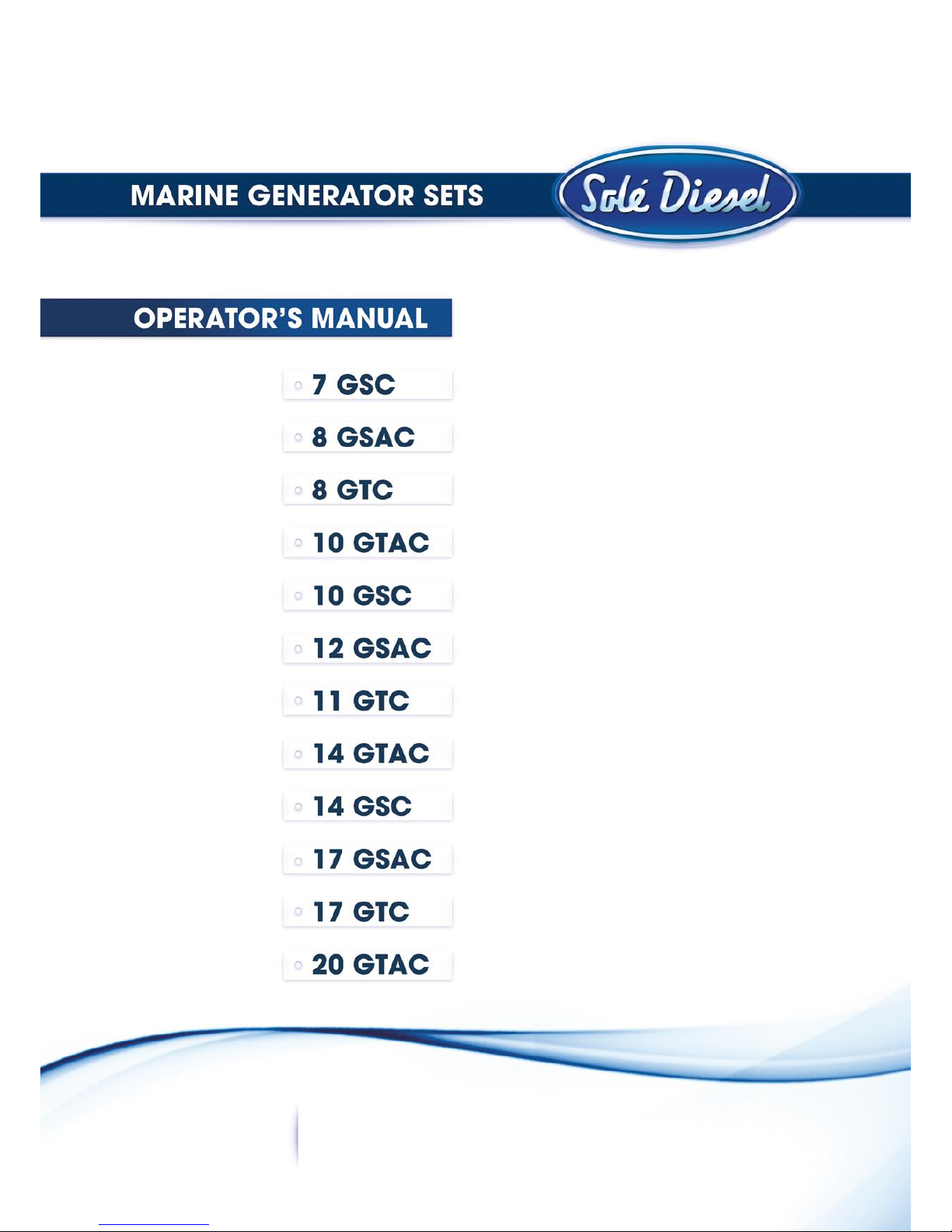
Fig. 1. Warning label. In case of fire
Never add fuel to the tank while the engine is running because spilled fuel may ignite on contact with
hot parts or from sparks. Catch fuels in an approved container when removing the fuel line or fuel
system. Keep the fuel lines and connections tight and in good condition. Do not replace flexible fuel lines
with rigid lines and use flexible sections to avoid fuel line breakage caused by vibrations.
Keep the compartment and the genset clean and free of debris to minimize the risk of fire.
Servicing the air cleaner. A sudden backfire can cause severe injury or death.
Do not operate the genset with the air cleaner/silencer removed.
Combustible materials. A fire can cause severe injury or death.
Genset fuels, fuel vapors and combustible materials are flammable and explosive. Handle these
materials carefully to minimize the risk of fire or explosion. Equip the compartment or nearby area with
a fully charged fire extinguisher.

8
In case of fire do not open sound shield compartment and follow these instructions:
1. Shut down genset(s)
2. Continuously discharge entire contents of a halon or CO2portable fire extinguisher (or other
provision) immediately.
There are some aspects that you must
consider:
Obligations:
Operator Manual of genset. Read and
understand it before operating and
servicing the genset to ensure that you
follow safe operating practices and
maintenance procedures.
Grounding electrical equipment. Connect
genset to earth connection.
Hearing protection. Use it to avoid
hearing loss when you operate the
genset.
Fig. 2. Warning label. General precautions
Prohibitions:
Restricted Access. Only authorized personnel can access to genset space.
Do not burn garbage. It is necessary to offload the genset waste in a special place.
Do not smoke or permit flames or sparks to occur near sources of spilled fuel or fuel vapors.
Dangers:
Hazardous voltage. Operate the genset only when all guards and electrical enclosures are in place.
Before working on the genset disconnect it from the load by switching off the line circuit breaker.
Hot parts, coolant and steam. Stop the genset and allow it to cool before touching or removing any
genset part.
Moving parts. Keep hands, feet, hair, clothing and test leads away from the belts and pulleys when the
genset is running. Replace guards, screens and covers before operating the genset.
Before working on the genset or connected equipment, disable
the genset as follows:
(1) Set the genset controller (SCO 10) to OFF Mode.
(2) Disconnect the power input from battery.
(3) Disconnect the battery cables. Remove the negative (-)
lead first when disconnecting the battery. Reconnect the
negative (-) lead last when reconnecting the battery.
Follow these precautions to prevent the starting of the genset
by genset controller (SCO 10), remote start/stop switch, or
engine start command from a remote computer.
Fig. 3. Warning label. Rotating parts
9
Rev. 3
Other WARNINGS (no adhesive label):
Carbon monoxide (CO) can cause severe nausea, fainting or death.
Genset exhaust contains carbon monoxide gas. Carbon monoxide is an odorless, colorless, tasteless,
nonirritating gas that can cause death if inhaled for even a short time.
Get fresh air and do not sit, lie down or fall asleep if anyone shows signs of
carbon monoxide poisoning:
-Light-headedness, dizziness
-Physical fatigue, weakness in joints and muscles
-Sleepiness, mental fatigue, inability to concentrate or speak
clearly, blurred vision
-Stomachache, vomiting, nausea
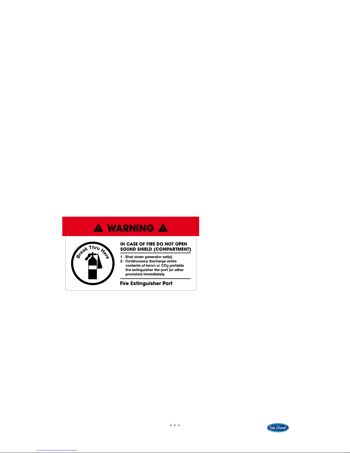
Fig. 4. Warning. Carbon monoxide
Keep the area around the battery well ventilated. While the engine is running
or the battery is charging, hydrogen gas is produced which can be easily ignited.
Never allow battery fluid (battery contains sulfuric acid) to come in contact
with clothing, skin or eyes. Always wear safety gloves and protective clothing
when servicing the battery. If battery fluid contacts the eyes and/or skin,
immediately flush the affected area with a large amount of clean water and
obtain prompt medical treatment.
Fig. 5. Warning. Battery charging
Never remove the cooler cap if the engine is hot. Steam and hot engine coolant
will spurt out and seriously burn you. Allow the engine to cool down before you
attempt to remove the cooler cap.
Fig. 6. Warning. Hot engine
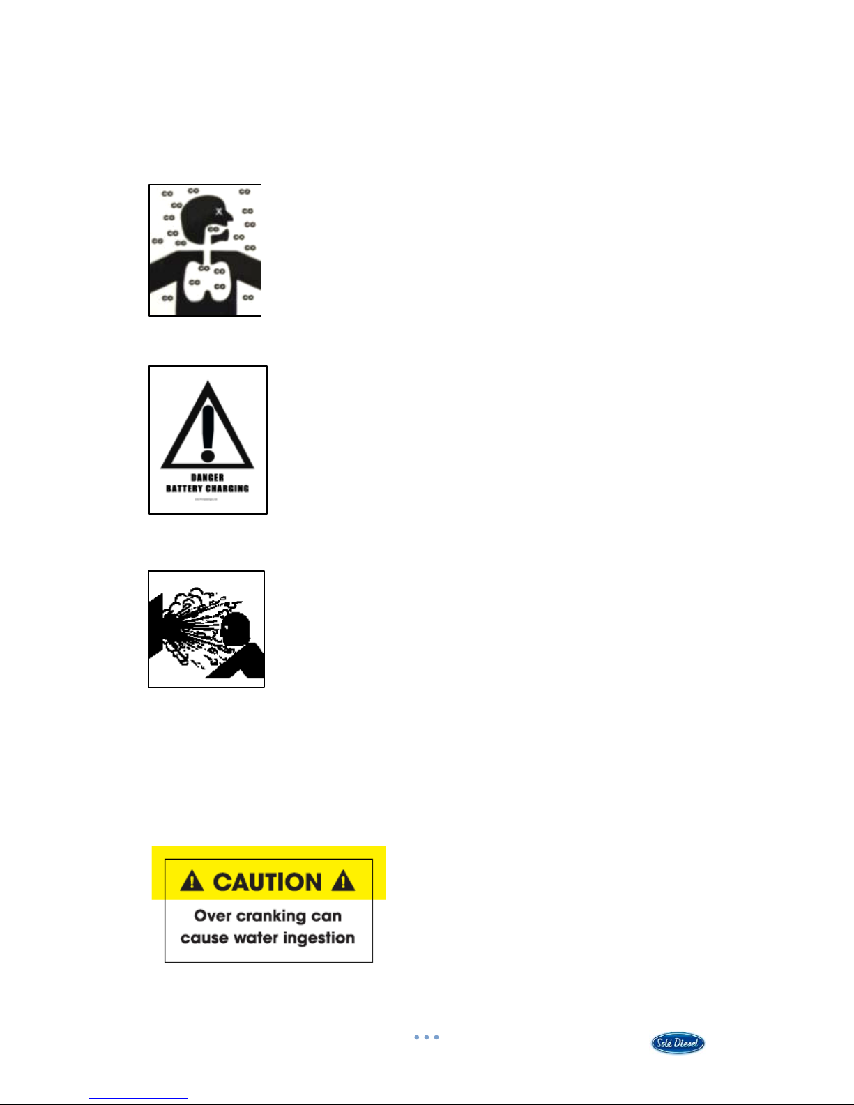
CAUTION
If the genset does not start after 3 crank attempts an overcrank fault occurs:
1) Close the seacock
2) Drain the water from the exhaust system at the
waterlock completely
3) Do not try to restart genset until the cause of
start fail is identified
Fig. 7. Caution label. Overcrank consequences

10
Do not use the cabin of the genset as a
step.
Using it as a step can cause the cabin
damage and, moreover, standing on the
genset could impair its operation.
Fig. 8. Caution label. Not a step
NOTICE
1. The installer / operator of the genset has to wear suitable CLOTHING for the workplace and the
situation; in particular, avoid loose clothes, chains, bracelets, rings and all accessories that
could become entangled with moving parts.
2. The installer / operator of the genset has to wear personal protective equipment such as
gloves, work shoes, eye and hearing protection as required by the task.
3. The area in which the operator is working has to be kept tidy and free of oil and other liquid
spillages and solid waste (metal chips, etc.).

11
Rev. 3
Service Assistance
For an updated list of our international distribution network, visit Dealers section in our web
page www.solediesel.com.
Or request this information by contacting Solé Diesel at:
e-mail: [email protected]
Phone: +34 93 775 14 00

12
Section 1 Genset Information
1.1 Genset Identification
MANUFACTURER:
SOLÉ, S.A.
Road from Martorell to Gelida, km 2
08760 MARTORELL
(BARCELONA) SPAIN
GENSET MODEL:
7 GSC / 8 GTC / 10 GSC / 11 GTC /
14 GSC / 17 GTC (1500 rpm)
8 GSAC / 10 GTAC / 12 GSAC / 14 GTAC /
17 GSAC / 20 GTAC (1800 rpm)
Fig. 9. Nameplate location
Fig. 10. Genset nameplate
The standard genset can run at ambient temperatures between -18ºC and +45ºC.

13
Rev. 3
1.2 Technical Specifications
8 GTC
7 GSC
11 GTC
10 GTAC
8 GSAC
14 GTAC
DIESEL ENGINE
General Information
Type
Water-cooled, Diesel 4-stroke cycle
Direction of rotation
Anti-clockwise observing genset from flywheel side
No. of cylinders - arrangement
3 - in line
Allowable Exhaust Back Pressure (kPa)
Max. 6,57
Timing
Pushrod and rocker arm with gear driven camshaft in
crankcase
Bore (mm)
76
76
78
Stroke (mm)
70
70
92
Total displacement (c.c.)
952
952
1318
Compression ratio
23:1
23:1
22:1
Ignition sequence
1-3-2
Fuel injection timing
BTDC 15º
BTDC 15º
BTDC 17º
Injection pressure (kPa)
13,73 (140 kg/cm2)
Inlet and exhaust valve clearance - cold
genset (mm)
0,25
RPM (rpm)
1500 (8 GTC)
1800 (10 GTAC)
1500 (7 GSC)
1800 (8 GSAC)
1500 (11 GTC)
1800 (14 GTAC)
Starting system
Electric-starter
Starting aid
Glow plugs
Lubrication System
System description
Forced lubrication by trochoid gear pump
Oil specifications
Use oil with 15W40 viscosity and no less than ACEA E5/E3 or
API CH-4/SJ quality
Oil pump
Trochoid gear type
Oil circuit capacity (l)
4,1
4,1
4,2
Lubrication oil pressure –nominal speed
(MPa)
0,29 –0,39 (3 –4 kgf/cm2)(2,9 –3,9 bar)
Min oil pressure - hot genset (MPa)
0,098 (1,0 kg/cm2)(0,98 bar)
Oil temperature –nominal speed (ºC)
60 - 95
Fuel System
System description
Electrical feed pump and mechanical injection pump
Fuel specifications
ASTM diesel diesel fuel No.2-D
Fuel injection pump
In-line type
Fuel injection nozzle
Throttle type
Cooling System
System description
Coolant circulation controlled by centrifugal pump with
thermostatic control and heat exchanger. Cooled exhaust
manifold.
Coolant specifications
KRAFFT ACU 2300 CC 50%
Coolant pump
Centrifugal type
Sea water pump
Centrifugal type
Coolant circuit capacity (l)
3,5
3,5
6,25
Thermostat valve
Start opening
End opening
+ 76,5ºC
+ 90ºC
Coolant temperature –nominal speed (ºC)
75 - 85

14
8 GTC
7 GSC
11 GTC
10 GTAC
8 GSAC
14 GTAC
DIESEL ENGINE
Inlet and
Exhaust
System
Air supply
Air cleaning by means of a dry-type air filter
Exhaust System
Cooled exhaust manifold
Dry exhaust manifold (optional equipment)
Electrical
System
Voltage –Polarity (V)
12 - ground
Alternator DC (A)
40
40
50
Starter motor (kW)
1,7
1,7
2
Glow plugs (A)
9,7 (10,5 V)
ALTERNATOR
General Information
Installation type
3-Phase
1-Phase
3-Phase
System cooler
Air fresh
Type
4 poles
Protection degree
IP23
Excitation system
Brushless
Power Factor (cos φ)
0,8
1
0,8
Insulation system
H
Voltage variation (V)
± 1
Frequency variation (Hz)
± 3
GENSET
General Information
Active stand-by power (kW/CV)
6,3 (8 GTC)
7,6 (10 GTAC)
6,6 (7 GSC)
8,0 (8 GSAC)
8,4 (11 GTC)
10,9 (14 GTAC)
Apparent stand-by power (kVA)
7,8 (8 GTC)
9,4 (10 GTAC)
6,6 (7 GSC)
8,0 (8 GSAC)
10,5 (11 GTC)
13,6 (14 GTAC)
Voltage (V)
400 / 230
(8 GTC)
480 / 277
(10 GTAC)
230 / 115
(7 GSC)
240 / 120
(8 GSAC)
400 / 230
(11 GTC)
480 / 277
(14 GTAC)
Frequency (Hz)
50 (8 GTC)
60 (10 GTAC)
50 (7 GSC)
60 (8 GSAC)
50 (11 GTC)
60 (14 GTAC)
Current Υ / Δ (A)
12 / 20
29 (7 GSC)
34 (8 GSAC)
17 / 28
Installation
Ø Int. Hose, sea water inlet (mm)
20
Ø Int. Hose, diesel fuel inlet (mm)
8
Ø Int. Hose, exhaust outlet1(mm)
50
Air admission displacement -max. rpm
(m3/h)
210-260
210-260
220-280
Minimum battery capacity (Ah)
60 (12V)
60 (12V)
80 (12V)
Length of battery wire (m)
≤ 1,5
Minimal section of battery wire (mm2)
60
Table 1. Technical Specifications 8 GTC / 10 GTAC / 7 GSC / 8 GSAC / 11 GTC / 14 GTAC
1
For each curve of 90º of the installation, must increase 10 mm (for lengths superior to 3 m).

15
Rev. 3
10 GSC
17 GTC
14 GSC
12 GSAC
20 GTAC
17 GSAC
DIESEL ENGINE
General Information
Type
Water-cooled, Diesel 4-stroke cycle
Direction of rotation
Anti-clockwise observing genset from flywheel side
No. of cylinders - arrangement
3 - in line
4 - in line
4 - in line
Allowable Exhaust Back Pressure (kPa)
Max. 6,57
Timing
Pushrod and rocker arm with gear driven camshaft in
crankcase
Bore (mm)
78
Stroke (mm)
92
Total displacement (c.c.)
1318
1758
1758
Compression ratio
22:1
22:1
22:1
Ignition sequence
1-3-2
1-3-4-2
1-3-4-2
Fuel injection timing
BTDC 17º
Injection pressure (kPa)
13,73 (140 kg/cm2)
Inlet and exhaust valve clearance - cold
genset (mm)
0,25
RPM (rpm)
1500 (10 GSC)
1800 (12 GSAC)
1500 (17 GTC)
1800 (20 GTAC)
1500 (14 GSC)
1800 (17 GSAC)
Starting system
Electric-starter
Starting aid
Glow plugs
Lubrication System
System description
Forced lubrication by trochoid gear pump
Oil specifications
Use oil with 15W40 viscosity and no less than ACEA E5/E3 or
API CH-4/SJ quality
Oil pump
Trochoid gear type
Oil circuit capacity (l)
4,2
6
6
Lubrication oil pressure –nominal speed
(MPa)
0,29 –0,39 (3 –4 kgf/cm2)(2,9 –3,9 bar)
Min oil pressure - hot genset (MPa)
0,098 (1,0 kg/cm2)(0,98 bar)
Oil temperature –nominal speed (ºC)
60 - 95
Fuel System
System description
Electrical feed pump and mechanical injection pump
Fuel specifications
ASTM diesel diesel fuel No.2-D
Fuel injection pump
In-line type
Fuel injection nozzle
Throttle type
Cooling System
System description
Coolant circulation controlled by centrifugal pump with
thermostatic control and heat exchanger. Cooled exhaust
manifold.
Coolant specifications
KRAFFT ACU 2300 CC 50%
Coolant pump
Centrifugal type
Sea water pump
Centrifugal type
Coolant circuit capacity (l)
6,25
8
8
Thermostat valve
Start opening
End opening
+ 76,5ºC
+ 90ºC
Coolant temperature –nominal speed (ºC)
75 - 85

16
10 GSC
17 GTC
14 GSC
12 GSAC
20 GTAC
17 GSAC
DIESEL ENGINE
Inlet and
Exhaust
System
Air supply
Air cleaning by means of a dry-type air filter
Exhaust System
Cooled exhaust manifold
Dry exhaust manifold (optional equipment)
Electrical
System
Voltage –Polarity (V)
12 - ground
12 / 24 (24V is optional) - ground
Alternator DC (A)
50
50 (12V) / 55 (24V)
Starter motor (kW)
2
Glow plugs 12V (A)
9,7 (10,5 V)
ALTERNATOR
General Information
Installation type
1-Phase
3-Phase
1-Phase
System cooler
Air fresh
Type
4 poles
Protection degree
IP23
Excitation system
Brushless
Power Factor (cos φ)
1
0,8
1
Insulation system
H
Voltage variation (V)
± 1
Frequency variation (Hz)
± 3
GENSET
General Information
Active stand-by power (kW/CV)
9,4 (10 GSC)
12,0 (12 GSAC)
13,2 (17 GTC)
15,6 (20 GTAC)
13,9 (14 GSC)
16,4 (17 GSAC)
Apparent stand-by power (kVA)
9,4 (10 GSC)
12,0 (12 GSAC)
16,4 (17 GTC)
19,5 (20 GTAC)
13,9 (14 GSC)
16,4 (17 GSAC)
Voltage (V)
230 / 115
(10 GSC)
240 / 120
(12 GSAC)
400 / 230
(17 GTC)
480 / 277
(20 GTAC)
230 / 115
(14 GSC)
240 / 120
(17 GSAC)
Frequency (Hz)
50 (10 GSC)
60 (12 GSAC)
50 (17 GTC)
60 (20 GTAC)
50 (14 GSC)
60 (17 GSAC)
Current Υ / Δ (A)
41 (10 GSC)
50 (12 GSAC)
24/41
61 (14 GSC)
69 (17 GSAC)
Installation
Ø Int. Hose, sea water inlet (mm)
20
ØInt. Hose, diesel fuel inlet (mm)
8
ØInt. Hose, exhaust outlet2(mm)
50
Air admission displacement -max. rpm
(m3/h)
220-280
240-300
240-300
Minimum battery capacity (Ah)
80 (12V)
80 (12V) / TBD
(24V)
80 (12V) / TBD
(24V)
Length of battery wire (m)
≤ 1,5
Minimal section of battery wire (mm2)
60
Table 2. Technical Specifications 10 GSC / 12 GSAC / 17 GTC / 20 GTAC / 14 GSC / 17 GSAC
2
For each curve of 90º of the installation, must increase 10 mm (for lengths superior to 3 m).

17
Rev. 3
1.3 Genset Limited Warranty
The genset is designed and built as a power unit for generating electrical energy: ALL USES
OTHER THAN THE PRESCRIBED APPLICATION AUTOMATICALLY RELEASE SOLÉ S.A. FROM LIABILITY FOR
DAMAGES THAT MAY ENSUE. In any event, the use of products other than those agreed upon at the
time of purchase RELEASES SOLÉ S.A. FROM ALL LIABILITY FOR DAMAGE TO THE GENSET OR PROPERTY
OR INJURY TO PERSONS.
Solé Diesel guarantees that at the time of shipment all its gensets comply with the provided
specifications and do not have any manufacturing defects.
The limited warranty provided by Solé Diesel enters into force from the time of sale to the first
end-purchaser or user of the genset. In the event that the product is not immediately delivered to the
end-customer, the warranty shall enter into force 6 months after the date of sale. Any limited warranty
period that has not elapsed can be transferred to the following purchaser(s).
Unless authorized otherwise by Solé Diesel, the warranty period is applied according to the
time elapsed in months from the date of purchase or the limit of hours of operation (whichever occurs
first).
GENSET FOR
PROFESSIONAL USE
GENSET FOR
RECREATIONAL USE
MONTHS
HOURS
MONTHS
HOURS
LIMITED WARRANTY COVERAGE PERIODS
12
1000
24
1000
EXTENDED COVERAGE PERIODS
-
-
24
1000
Table 3. Limited warranty coverage periods
Extended coverage (only recreational gensets) is applied to the following components:
-Engine block
-Cylinder head
-Crankshaft
-Camshaft
-Flywheel housing
-Timing gear housing
-Timing gear
-Conrod
RESTRICTIONS
Coverage:
a) The warranty covers any failure of the product under normal operating conditions caused by
a defect in manufacturing.
b) The warranty covers the labour costs necessary to replace and/or repair the defective
original components, according to Solé Diesel standards of excellence. The time period covered
for these operations is limited to 4 hours.

18
c) The warranty covers reasonable costs of travel required to carry out the necessary
operations. The travel distance is limited to 300 kilometers in conjunction with a travel time of
3 hours.
Excluded from coverage:
a) If Solé Diesel products are installed and used alongside other products not designed or
manufactured by Solé Diesel that affect their operation, the warranty shall apply exclusively to
the Solé Diesel products and shall not apply if the products from another manufacturer are
inappropriate for use alongside Solé Diesel products or are the cause of the failure or poor
operation of our products.
b) The warranty shall not apply if the revisions and maintenance services indicated in this
manual have not been adhered to properly.
c) Deterioration resulting from time of storage exceeding 6 months and/or storage conditions
that do not comply with the procedures described in this manual.
d) Deterioration resulting from not complying with the procedure for winter storage while the
engine is not in service, as described in this manual.
e) Faults due to negligence, lack of service, accidents, abnormal use and inadequate service or
installation.
f) Faults due to the use of components not manufactured or sold by Solé Diesel.
g) Faults due to electrical installations that do not comply with Solé Diesel design specifications
or are not expressly approved by Solé Diesel.
h) Faults due to the use of and operation with fuels, oils or lubricants that are not authorized by
Solé Diesel.
i) Faults due to water entering the cylinder(s) through the exhaust system.
j) Failure for general omission of the procedures described in this manual.
k) Components subjected to normal operating wear and tear.
l) Costs due to phone communications, loss of time or money, discomfort, launching,
grounding, removal or replacement of vessel parts or materials because the design of the vessel
makes it necessary to do so to access the genset, and damage and/or accidents caused as a
result of a failure.
For more information, consult the Warranty Manual.
AFTER-SALES SERVICE CONTACT
You can contact with the nearest authorized Solé Diesel dealer (see chart of Solé Diesel Dealers
in the Service Assistance section).

19
Rev. 3
Section 2 Transport, Handling and Storage
2.1 Receipt
When the genset is delivered make sure that the packing has not been damaged during
transport and that it has not been tampered with or that components inside the packing have been
removed (see information marked on covers, bases and cartons).
Place the packed genset as close as possible to the place of installation and remove the packing
material, checking that the goods supplied correspond to the order specifications.
NOTICE
If you notice damage or missing parts, inform SOLÉ S.A. after-sales departments and the carrier
immediately and forward photographic evidence of the damage.
After inspecting the goods if you notice damage, write a reservation on the delivery note. Have
the carrier countersign the note and advise SOLÉ S.A., preferably by mail (sole@solediesel.com).
2.2 Transporting and Handling the Packed Genset
When lifting and transporting the genset use EXCLUSIVELY a forklift or bridge crane of
appropriate load capacity, with chains equipped with safety hooks suitable for lifting the load.
The use of any other system automatically invalidates the insurance guarantee against possible
damage to the genset.
To unpack the genset, you must follow these steps:
1. Remove the cardboard crate.
2. Lift the genset using a forklift and suitable chains, which hook to the genset eyebolts.
3. Transfer the genset to the intended position of installation.
4. Remove the wooden base.
5. Begin installation operations.
Fig. 11. Packed genset
This manual suits for next models
7
Table of contents
Other Sole Diesel Portable Generator manuals

Sole Diesel
Sole Diesel 7 GS/GSC User manual

Sole Diesel
Sole Diesel 85 GTC User manual

Sole Diesel
Sole Diesel 85 GT User manual

Sole Diesel
Sole Diesel 29 GS/GSC User manual

Sole Diesel
Sole Diesel 29 GS User manual

Sole Diesel
Sole Diesel G-8M-3 User manual

Sole Diesel
Sole Diesel 20 GSC DNV User manual

Sole Diesel
Sole Diesel G-20T-15 User manual

Sole Diesel
Sole Diesel 7 GS User manual

Sole Diesel
Sole Diesel 165 GT User manual


