Sole Digital HNG100 User manual

© CASWA Pty Ltd –2014 1 | Page
HOISTNET GATEWAY
Model HNG100, Version 1+
Installation and User Manual
Revision 02 –December 2018
© CASWA Pty Ltd –2014

© CASWA Pty Ltd –2014 2 | Page
CONTENTS
1OVERVIEW............................................................................................................................3
2SPECIFICATIONS....................................................................................................................3
2.1 Physical Specifications ............................................................................................................3
2.2 Electrical Specifications...........................................................................................................4
2.3 Communication Specifications................................................................................................4
3INSTALLATION DETAILS.........................................................................................................5
3.1 Prior to Installation .................................................................................................................5
3.2 Wiring Diagrams......................................................................................................................6
3.2.1 Using Analog Outputs ..............................................................................................6
3.2.2 Connecting RS485 Outputs ......................................................................................7
4COMMISSIONING DETAILS ....................................................................................................7
4.1 Installing and Launching the FSU Application.........................................................................7
4.1.1 FSU Program Installation..........................................................................................7
4.1.2 Installing the FSU application...................................................................................8
4.1.3 Launching the application........................................................................................8
4.2 Connecting to the Device........................................................................................................8
4.3 Checking for Firmware............................................................................................................9
4.4 HoistNet GateWay Configuration Screen .............................................................................11
4.4.1 Setting the ID..........................................................................................................11
4.4.2 Setting/Changing the HoistNet Inputs ...................................................................11
4.5 Configuring Analog Outputs..................................................................................................13
4.6 Configuring RS485 Outputs...................................................................................................13
5ROUTINE MAINTENANCE .................................................................................................... 14
6TROUBLESHOOTING............................................................................................................ 14
APPENDIX A: FSU SYSTEM REQUIREMENTS................................................................................. 15
© CASWA Pty Ltd –2014 3 | Page
1OVERVIEW
The HoistNet GateWay is a device for receiving up to two signals from other HoistNet devices and
outputting the load via two fully isolated sinking or sourcing 4-20mA channels and/or a
programmable RS485 serial interface.
2SPECIFICATIONS
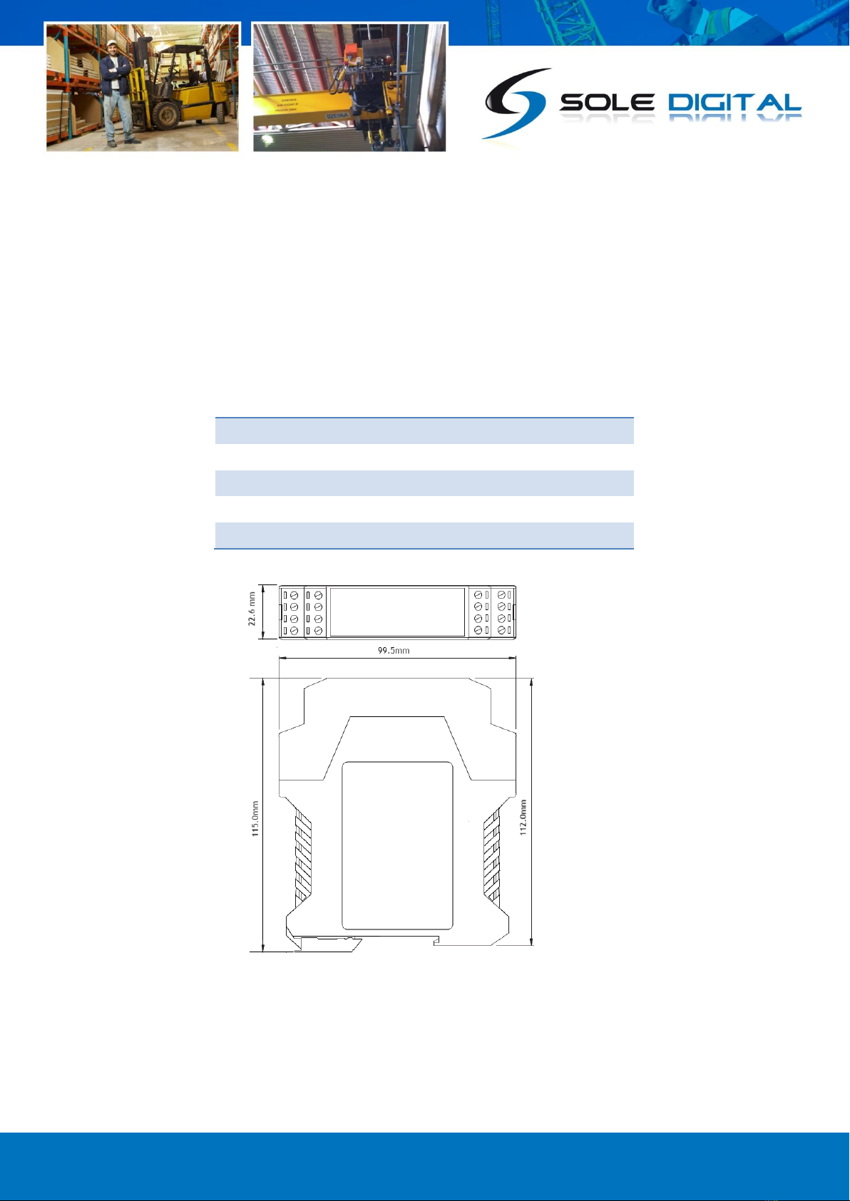
2.1 Physical Specifications
Overall length (mm):
115
Overall width (mm):
100
Overall height (mm):
23
Weight (kg):
0.12
Mounting:
30mm DIN Rail
Figure 1: Case Dimensions
© CASWA Pty Ltd –2014 4 | Page
2.2 Electrical Specifications
Parameter
Description
Min
Typ
Max
Units
Vin
Supply voltage
24
250
VAC
Iin
Supply current
7
8
12
mA
Aimin
Analogue channel minimum output current
3
3.5
4
mA
Aimax
Analogue channel maximum output current
22
25
28
mA
Visolate
Isolation on analog and digital outputs
2000
V
Vheadroom
Voltage drop across analog output
3
5
8
VDC
Allowable operating temperature
-25
85Note1
°C
Note1: Extended operation at maximum temperature will reduce the life the device.
2.3 Communication Specifications
Communications between the device and a host is usually via a Bluetooth radio link. The Bluetooth
device name will be set to the Crane ID, the PIN is 0000.
For more details on the communication protocol used to communicate with the HoistNet GateWay,
contact support@caswa.com.
© CASWA Pty Ltd –2014 5 | Page
3INSTALLATION DETAILS
3.1 Prior to Installation
Before installing your HoistNet GateWay unit visually inspect the device and check that:
(a) the type of input marked on the front of the device is appropriate for your application;
(b) the case is not damaged and fits together securely;
(c) terminals are secure;
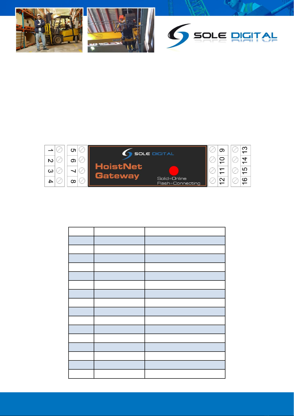
(d) terminal numbering is as per the following diagram.
NB: As each block of 4 terminals can be removed (for installation) it is important that they be
reinstalled in the positions shown.
Terminal
Function
Notes
1
0V
2
24-240V AC/DC
3
Tare 1
Connect to 0V to tare
4
Tare 2
5
4-20mA - (Chan 2)
6
No Connection
7
4-20mA + (Chan 2)
8
No Connection
9
4-20mA - (Chan 1)
10
4-2mA + (Chan 1)
11
RS485 Gnd
Isolated from
12
No Connection
13
A
14
B
15
Z
16
Y
Figure 2: Terminal Positions
© CASWA Pty Ltd –2014 6 | Page
3.2 Wiring Diagrams
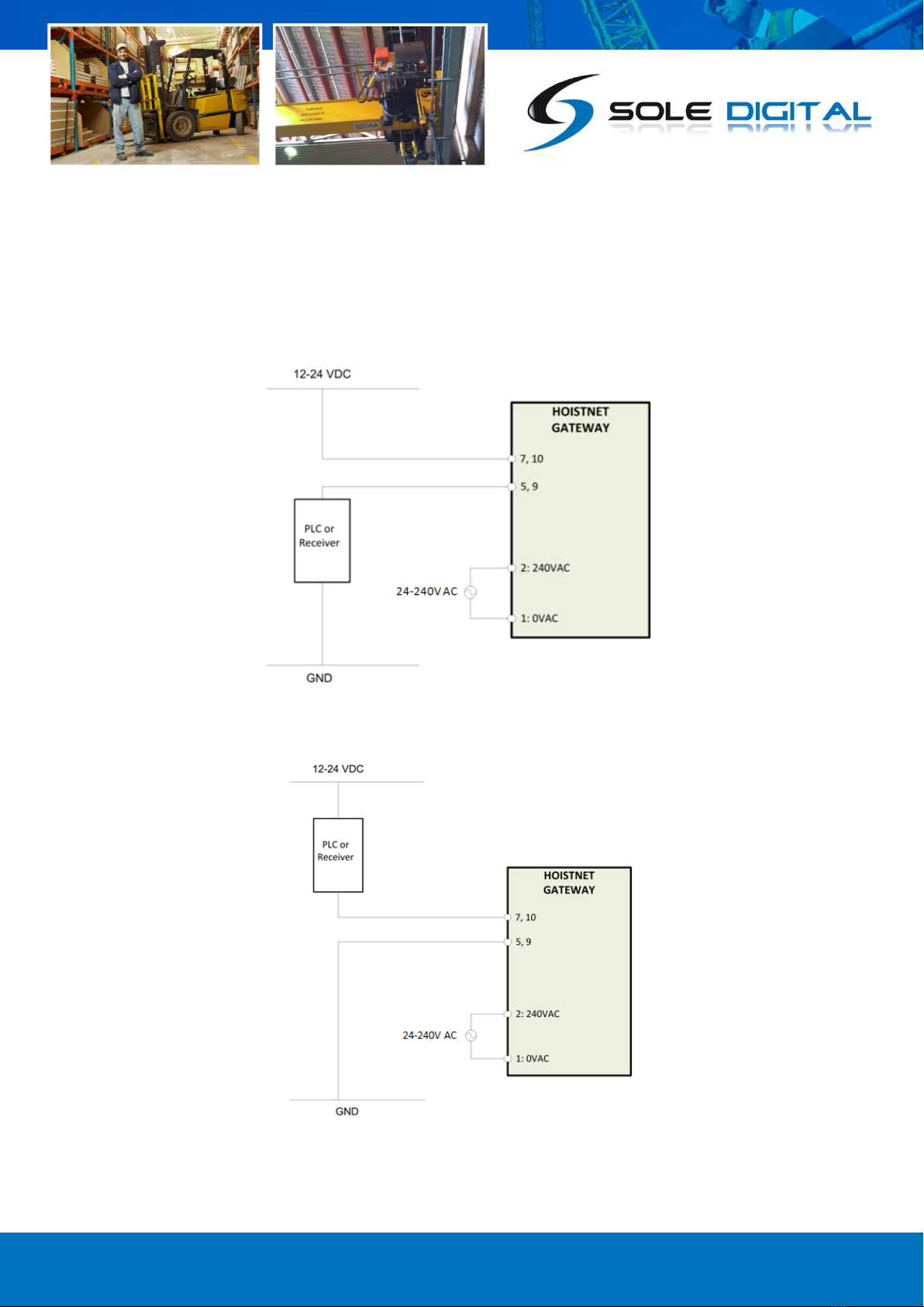
3.2.1 Using Analog Outputs
The Analog Outputs are fully isolated and can be wired up as either sourcing (See Figure 3) or sinking
outputs (See Figure 4).
Figure 3: Connecting the Analog Outputs as Sourcing Outputs
Figure 4: Connecting the Analog Outputs as Sinking Outputs

© CASWA Pty Ltd –2014 7 | Page
3.2.2 Connecting RS485 Outputs
Connect output RS485 terminals, marked Y and Z, on the HoistNet Gateway (terminals 16 and 15
respectively) to inputs A and B on the receiving device.
Note: Terminals 13 and 14 marked as A and B on the HoistNet GateWay are RS485 inputs.
Figure 5: Example of connecting the HoistNet GateWay to a RS485 receiver.
4COMMISSIONING DETAILS
HoistNet GateWay is designed to be commissioned using a laptop computer. You will need a CASWA
LINK-2 Bluetooth Modem and the Field Service Utility (FSU) software application loaded on a laptop.
4.1 Installing and Launching the FSU Application
4.1.1 FSU Program Installation
Ensure that your computer is switched on, connected to the internet and that the minimum required
software versions are installed (see Appendix A for minimum system requirements). Ensure that the
LINK-2 modem is installed and that the drivers have loaded.
© CASWA Pty Ltd –2014 8 | Page
4.1.2 Installing the FSU application
The latest FSU software can be downloaded from the following link and should be checked
periodically for updates: http://www.soledigital.com.au/Link2.html
4.1.3 Launching the application
Double click on the FSU program icon:
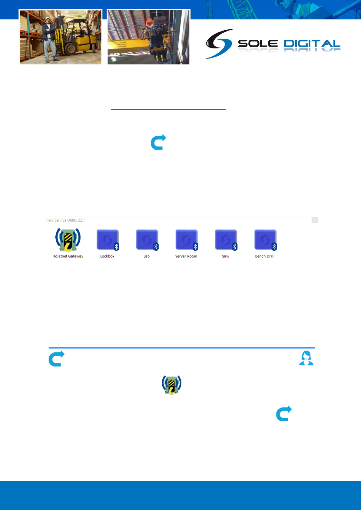
4.2 Connecting to the Device
The FSU will scan for Bluetooth enabled devices. This process takes approximately 10 seconds, when
complete a list of all Sole Digital devices within range will be displayed.
The HoistNet GateWay icon looks like this:
If the desired HoistNet GateWay unit is not found, ensure it is powered up and press to repeat
the search.
NB: The Bluetooth link between the Laptop using a Link-2 and a HoistNet GateWay has a range of
approximately 200m.
© CASWA Pty Ltd –2014 9 | Page
Double click the HoistNet GateWay you wish to configure to establish a connection.
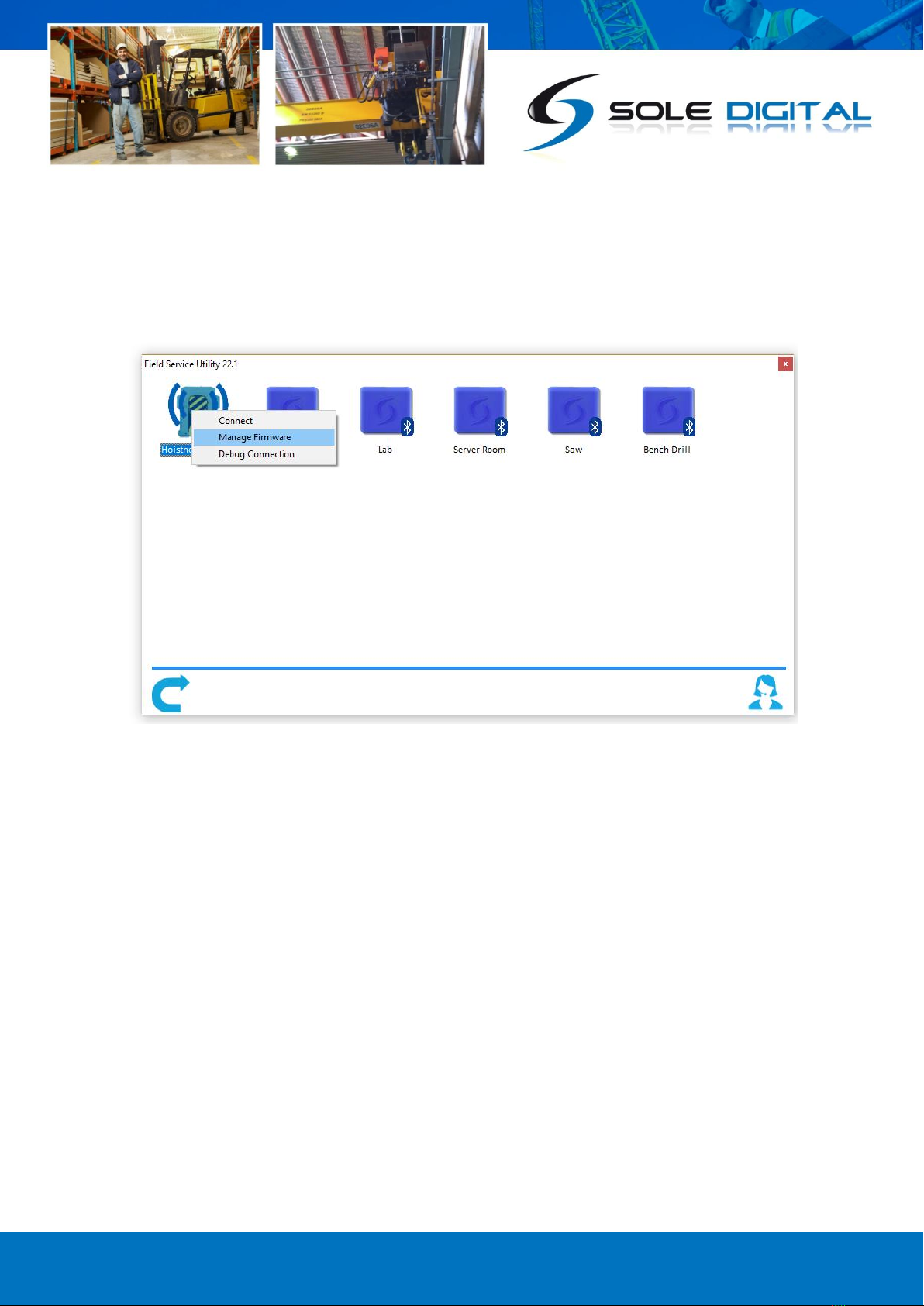
4.3 Checking for Firmware
To check the current firmware of the Hoistnet Gateway, right click on the Hoistnet Gateway Icon
within the FSU discovery screen and choose <manage firmware>.
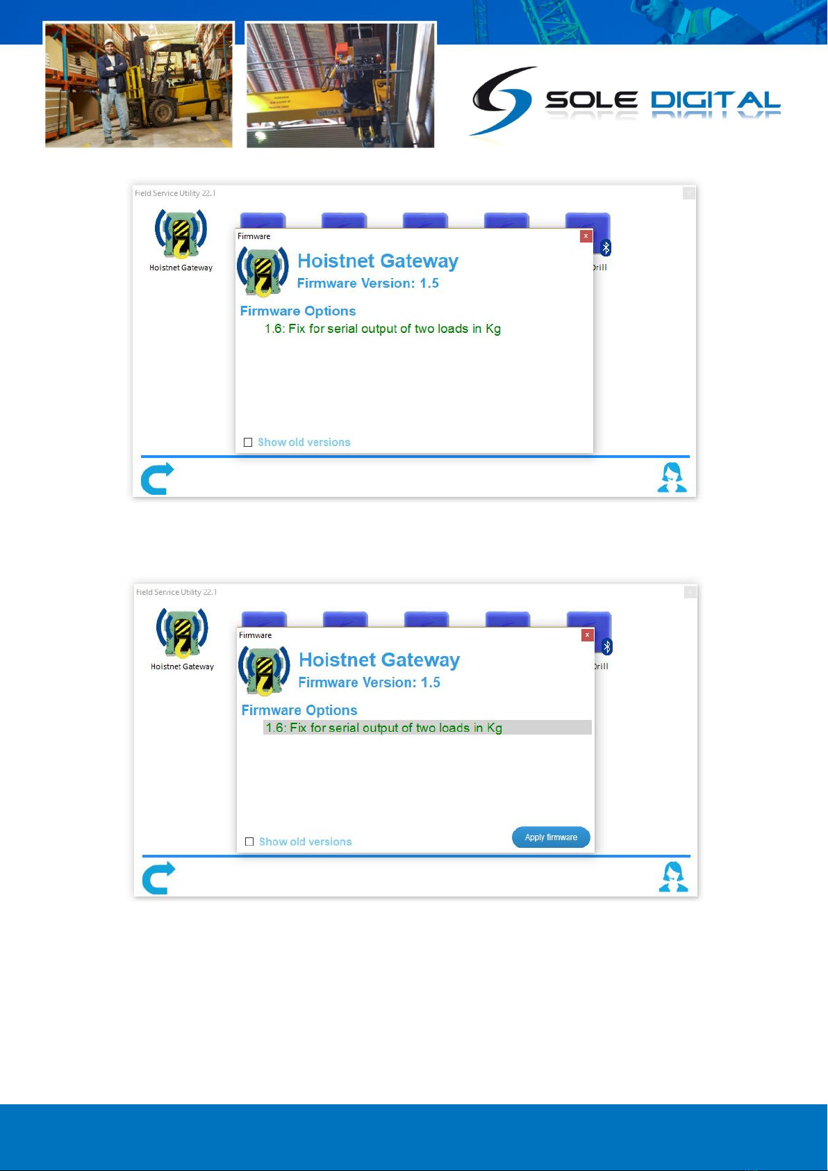
A new window will open. The FSU will establish a connection, check what version of firmware is
currently on the HoistNet GateWay and show you a selection of newer versions of firmware that are
available. If there are no new firmware versions available there will be no selections available to
pick.
© CASWA Pty Ltd –2014 10 | Page
When you pick the firmware you want to update the Hoistnet GateWay the <Apply Firmware>
button becomes visible. Click the <Apply Firmware> button to begin the firmware update.
A progress bar will begin showing how far along the firmware update is. When its complete it will
show a pop up message.
DO NOT switch off the computer or remove the LINK2 modem until this is complete –doing so
may leave the HoistNet GateWay in an unrecoverable state.

© CASWA Pty Ltd –2014 11 | Page
4.4 HoistNet GateWay Configuration Screen
Once you are up to date with the latest firmware version you can double click the Hoistnet GateWay
you want to configure and the following screen will appear.
This screen shows the:
ID (see section 4.4.1 for configuring this);
Names of HoistNet devices being used for inputs
and their connection status;
Current firmware version operating on the device.
A link to this user document.
4.4.1 Setting the ID
To set the ID of the device (commonly the Crane ID) click
on the <General> button to return to the first screen.
Type in the desired Crane identification in the ‘ID’ field.
This must be 18 characters or less.
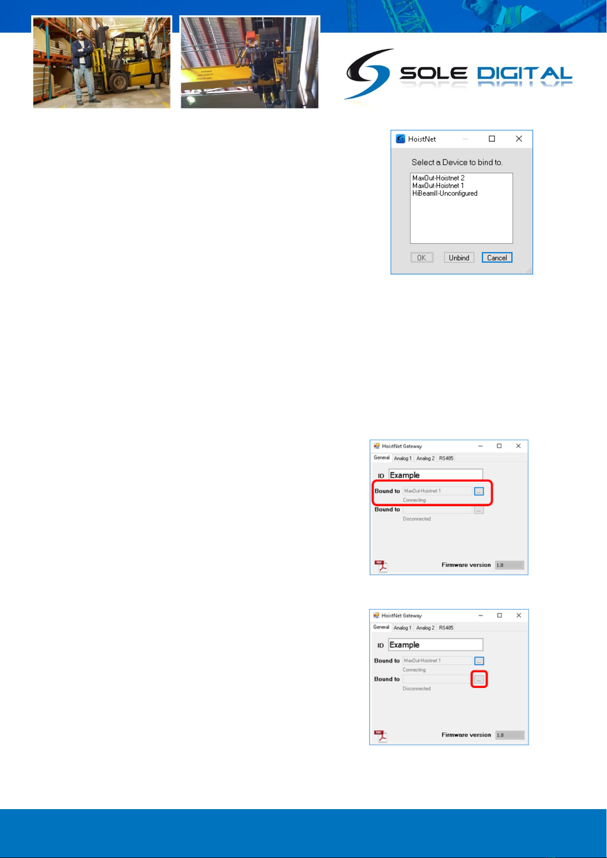
4.4.2 Setting/Changing the HoistNet Inputs
HoistNet GateWay devices obtain their load signals
wirelessly from other HoistNet enabled devices.
To select/change a HoistNet load for the first input press
the top <...> button:
© CASWA Pty Ltd –2014 12 | Page
A box will appear asking you which HoistNet enabled
device you want to connect to:
Select the device that has the load signal to be used and
press <OK>.
If you select a LiftlogXL, another window will popup asking you which hook to connect to (Main, Aux
or Combined Load). Select the desired option and press <OK>.
The popup window(s) will close and you will be returned to the General Configuration Screen.
The bound device will now be shown in the first 'Bound to' field and will indicate that its status has
changed to Online.
NB: You will need to ensure that the originating HoistNet
load signal has been calibrated correctly and is powered on.
If you want to bind the second input, repeat the process by
pressing the lower <...> button:
To unbind a HoistNet GateWay input from a HoistNet
device, or to change the bound device, press the <Bind>
button on the Load screen and then select <Unbind> on the
popup box.
© CASWA Pty Ltd –2014 13 | Page
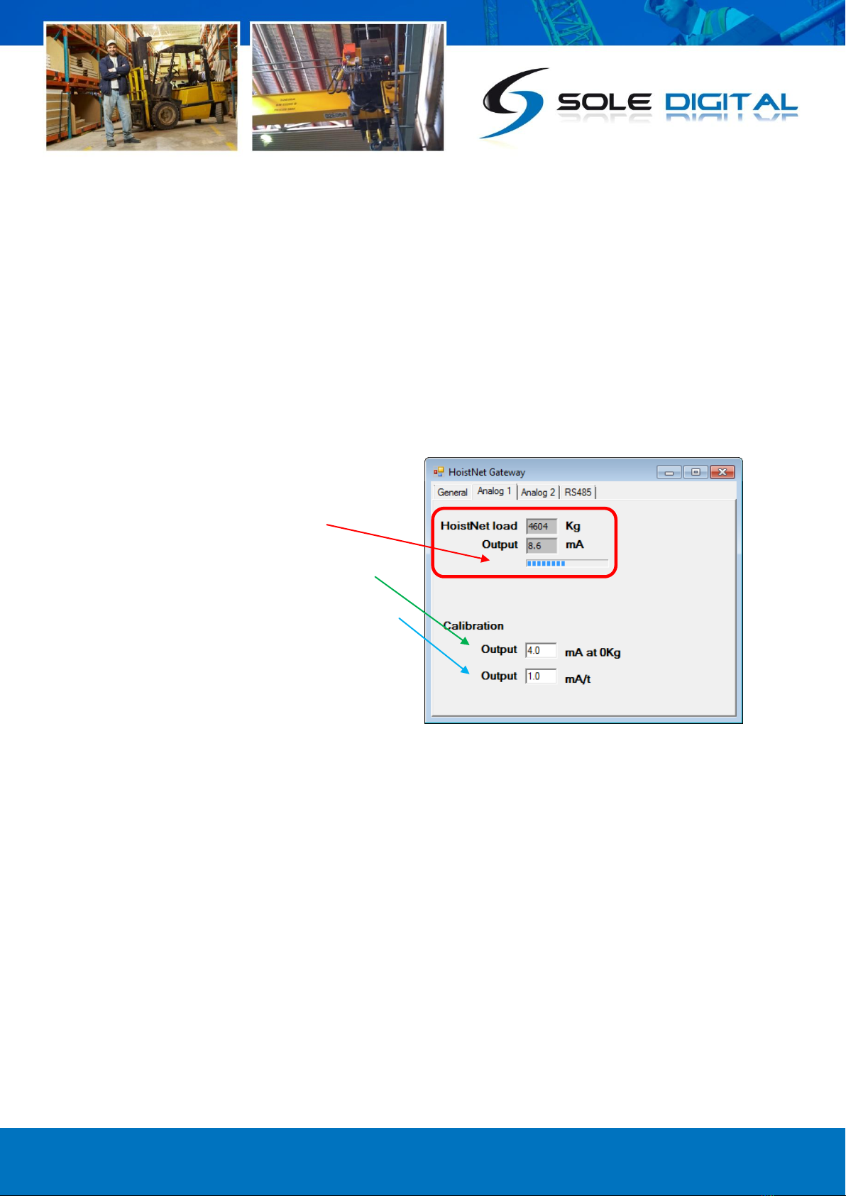
4.5 Configuring Analog Outputs
A HoistNet GateWay can convert the HoistNet inputs into analog 4-20mA outputs. The behaviour of
each output needs to be configured using the 'Analog 1' and 'Analog 2' tabs for the first and second
input respectively.
To configure the 4-20mA output signal, two parameters are required:
(a) The expected mA output value corresponding to a 0kg load; and
(b) The expected mA signal output per tonne of load.
To calibrate the first 4-20mA output, press the 'Analog 1' tab to bring up the following screen:
The Hoistnet load in kg and respective mA
output is shown at the top of the screen. The
percentage of the 4-20mA output range being
utilised is shown in the signal bar.
To configure the 0kg signal level, enter the
expected mA level in the top Output field.
Enter the mA/tonne in the lower Output field.
If you are using a second HoistNet input, press
the Analog 2 tab and repeat the process for the
second output.
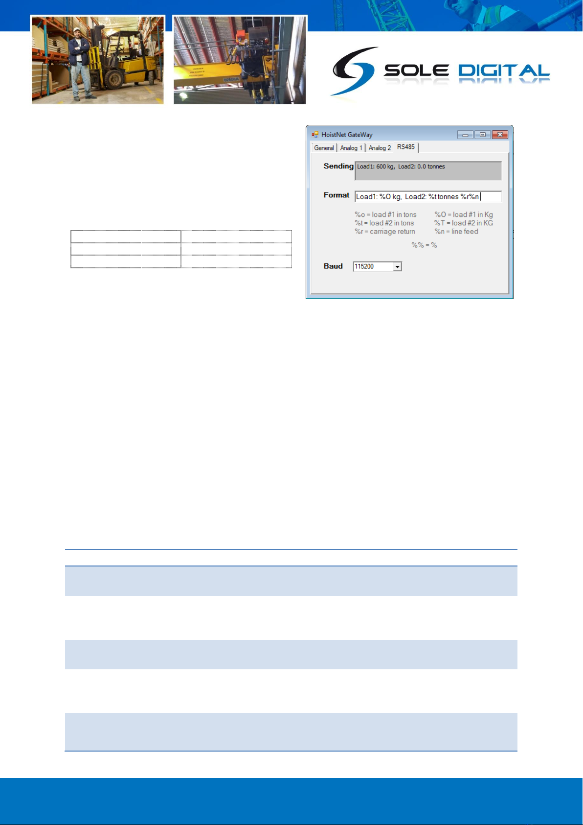
4.6 Configuring RS485 Outputs
One or both load signals can also be output via a RS485 connection. To enable this, select the
'RS485' tab to bring up the following screen:
© CASWA Pty Ltd –2014 14 | Page
This screen contains the two configurable RS485
fields and also shows the resulting string being
sent via the RS485 interface.
Define the required RS485 serial format in the
'Format' field incorporating the required loads
using the following codes:
%o = first load in tonnes
%O = first load in kilograms
%t = second load in tonnes
%T = second load in tonnes
%r = carriage return
%n = line feed
Preceding or succeeding text can also be added. Note that to incorporate a percentage character,
you need to enter two %% characters.
The resulting string is visible in the 'Sending' field.
It is also important to define the communication speed by selecting the speed from the 'Baud'
selection box. This must match the speed set on the device that will be using the RS485 information.
5ROUTINE MAINTENANCE
There is no routine maintenance for this device.
6TROUBLESHOOTING
Fault
Cause
Fix
Unable to connect to
GateWay unit from FSU
GateWay or FSU are
busy
Power cycle the crane.
Incorrect wiring
Check that wiring is as per section 3.2.
Check that removable terminals have been reinserted
into their correct positions as shown in Figure 2.
Pluggable terminals
not seating correctly.
Replace pluggable terminal and rewire the associated
terminals.
The GateWay is reporting
no load from a remote
device
Remote Device is not
communicating
Power cycle remote device then power cycle the
HoistNet Gateway
GateWay not connecting
to remote device
Remote device not
responding to
connection request
Power cycle both devices

© CASWA Pty Ltd –2014 15 | Page
Analog Output current
“Maxing out”
Insufficient excitation
voltage.
Ensure at least 8V Headroom for Gateway in current
loop
No current in analog
output loop
Reverse polarity
Check the wiring to the Gateway
APPENDIX A: FSU SYSTEM REQUIREMENTS
The minimum requirements for operating CASWA’s Field Service Utility (FSU) and Link-2 Bluetooth
modem are:
Laptop computer running Windows XP SP3 or later;
One Spare USB port;
Microsoft .NET framework 3.5.
Table of contents
Other Sole Digital Gateway manuals

Popular Gateway manuals by other brands

ZyXEL Communications
ZyXEL Communications AMG1202-T10A Quick start quide

Merlin
Merlin GRIFCO myQ Installation and operating instructions

AT&T
AT&T U-verse TV Self-installation guide

Nortel
Nortel Internet BWA System 3200 user manual

ZyXEL Communications
ZyXEL Communications ZYWALL USG 20W Brochure & specs

Belkin
Belkin BU3DC000-12V user manual


