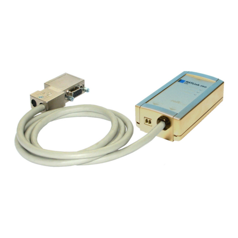
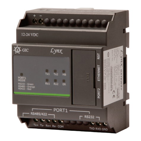
NetLink 700-883-PRO42 User manual

Systeme Helmholz GmbH zHannberger Weg 2 z91091 Großenseebach zGermany
Phone: +49 9135 7380-0 zFax: +49 9135 7380-110 zE-Mail: [email protected] zInternet: www.helmholz.de
Ethernet Gateway for MPI/PPI/PROFIBUS
700-883-PRO42
User Manual
Edition 2 / 29.03.2010
HW 1-1, FW 2.30 and higher
Order number of manual: 900-883-PRO42/en


All rights are reserved, including those of translation, reprinting, and
reproduction of this manual, or parts thereof. No part of this manual
may be reproduced, processed, copied, or transmitted in any way
whatsoever (photocopy, microfilm, or other method) without the
express written permission of Systeme Helmholz GmbH, not even
for use as training material, or using electronic systems. All rights
reserved in the case of a patent grant or registration of a utility
model or design.
Copyright ©2009 by
Systeme Helmholz GmbH
Hannberger Weg 2, 91091 Grossenseebach, Germany
Note:
We have checked the content of this manual for conformity with
the hardware and software described. Nevertheless, because devia-
tions cannot be ruled out, we cannot accept any liability for com-
plete conformity. The information in this manual is regularly up-
dated. When using purchased products, please heed the latest ver-
sion of the manual, which can be viewed in the Internet at
www.helmholz.de, from where it can also be downloaded.
Our customers are important to us. We are always glad to receive
suggestions for improvement and ideas.
STEP ,Protool, Starter, Micromaster, and SIMATIC are registered trademarks of SIEMENS AG
MS-DOS and Windows are registered trademarks of Microsoft Corporation.

Revision history of this document:
Edition Date Revision
1 18.08.2009 First Edition
2 29.03.2010 Change cross-cable in the scope of supply, new Web Interface fea-
tures added

NETLink®Switch 5
Contents
1Safety Information 8
1.1 General 8
1.2 Restriction of access 9
1.3 Information for the user 9
1.4 Use as intended 9
1.5 Avoiding use not as intended! 9
2Installation and Mounting 10
2.1 Mounting orientation 10
2.2 Minimum clearance 10
2.3 Installing the module 10
3System Overview 11
3.1 Application and function description 11
3.2 Connections 12
3.3 LED displays and Connectors 12
3.4 Items supplied 13
3.5 Accessories 13
3.5.1 Manuals 13
3.5.2 Software 13
3.5.3 Other accessories 13
3.5.4 PROFIBUS accessories 14
4Installation of the driver software 15
4.1 Introduction 15
4.2 System requirements 15
4.3 Running the installation setup 15
4.3.1 Adding the interface to the PG/PC interface 16
4.3.2 Selecting the required interface parameterization 17
5Configuration via the NETLink-S7-NET Driver 18
5.1 Bus settings 18
5.1.1 MPI 19
5.1.2 PROFIBUS configuration 20
5.1.3 PPI configuration 23
5.2 Local connection (TCP parameterization) 23

NETLink®Switch6
5.2.1 Creating a station 24
5.2.2 Setting TCP parameters 26
5.2.3 Operation without the DHCP 27
5.2.4 DHCP 28
5.2.5 Additional features 28
5.3 Options of the driver 29
5.3.1 Language setting of the display elements 29
5.3.2 Version information 29
5.4 Diagnostics 30
5.4.1 Bus members 30
5.4.2 Bus parameters 30
5.5 Teleservice 31
6The Tool: ‘NETLink®PRO Family Configuration’ 32
7Possibilities of the Web Interface 33
7.1 Home page 33
7.2 Status page 34
7.3 Configuration page 38
7.4 Security page 41
7.5 Observing variables 43
8RFC1006 Function (S7-TCP/IP) 46
9Bus Parameters in Single Master Operation 47
9.1 Storing specified bus parameters 47
9.2 Addressing (rack/slot mode ON/OFF) 48
9.2.1 Addressed mode 49
9.2.2 Rack/slot mode 49
9.3 Example of configuration for WinCC V7.0 50
9.3.1 Using addressed mode 50
9.3.2 Use of rack/slot mode 53
10 Troubleshooting 57
11 Appendix 62
11.1 Technical Data 62
11.2 Pin assignments 62
11.2.1 MPI/PROFIBUS interface pin assignments 62
11.2.2 Assignment of the Ethernet interface (host interface) 62
11.2.3 Function overview of internal switch 63

NETLink®Switch 7
11.2.4 Power supply socket 63
11.3 Further Documentation 63
11.4 Information in the internet 63
11.5 Address conversion table 64
12 Glossary 65

NETLink®Switch8
1Safety Information
For your own safety and for the safety of others, always heed the
safety information given here. The safety information indicates
possible hazards and provides information about how you can
avoid hazardous situations.
The following symbols are used in this manual.
!
Caution, indicates hazards and sources of error
i
Gives information
Hazard, general or specific
Danger of electric shock
1.1 General
NETLink®Switch is only used as part of a complete system.
!
The operator of a machine system is responsible for observing
all safety and accident prevention regulations applicable to the applica-
tion in question.
During configuration, safety and accident prevention rules spe-
cific to the application must be observed.
Emergency OFF facilities according to EN 60204 / IEC 204
must remain active in all modes of the machine system. The system
must not enter an undefined restart.
Faults occurring in the machine system that can cause damage
to property or injury to persons must be prevented by additional external
equipment. Such equipment must also ensure entry into a safe state in
the event of a fault. Such equipment includes electromechanical safety
buttons, mechanical interlocks, etc. (see EN 954-1, risk estimation).
Never execute or initiate safety-related functions using an op-
erator terminal.

NETLink®Switch 9
1.2 Restriction of access
The modules are open equipment and must only be installed in
electrical equipment rooms, cabinets, or housings. Access to the
electrical equipment rooms, barriers, or housings must only be
possible using a tool or key and only permitted to personnel hav-
ing received instruction or authorization.
1.3 Information for the user
This manual is addressed to anyone wishing to configure, use, or
install NETLink®Switch.
The manual tells the user how to operate NETLink®Switch and ex-
plains the signaling functions. It provides the installing technician
with all the necessary data.
NETLink®Switch is exclusively for use with a S7-200 and S7-
300/S7-400 programmable controller from Siemens.
NETLink®Switch is for use within a complete system only. For that
reason, the configuring engineer, user, and installing technician
must observe the standards, safety and accident prevention rules
applicable in the particular application. The operator of the auto-
mation system is responsible for observing these rules.
1.4 Use as intended
NETLink®Switch must only be used as a communication and sig-
naling system as described in the manual.
1.5 Avoiding use not as intended!
Safety-related functions must not be controlled via NETLink®
Switch alone. Make sure in the software that uncontrolled restarts
cannot occur.
Only authorized persons
must have access to the
modules!
D
uring configuration,
safety and accident pre-
vention rules specific to
the application must be
observed.
M
ake sure in
t
he soft-
ware that uncontrolled
restarts cannot occur.

NETLink®Switch10
2Installation and Mounting
Installation and mounting must be effected in compliance with
VDE 0100 / IEC 364. Because it is an IP20 module, you must install
it in a cabinet.
A maximum ambient temperature of 60 ºC must be ensured for re-
liable operation.
2.1 Mounting orientation
NETLink®Switch can be installed in any position.
2.2 Minimum clearance
Minimum clearances must be observed because
•Then it is possible to insert and remove NETLink®Switch with-
out having to remove other system components.
•There is enough space to connect existing interfaces and other
contacts using standard commercial type accessories.
For NETLink®Switch, a minimum clearance of 30 mm should be
left above and below and 10 mm at the sides.
2.3 Installing the module
NETLink®Switch is intended to be mounted on a DIN rail bracket.
It can be snapped into place by simply attaching it to the DIN rail
bracket. In order to do so, you hook NETLink®Switch into the rail
bracket at the upper groove of the DIN rail bracket and push NET-
Link®Switch in direction of the rail bracket. Thereupon, NETLink®
Switch should snap into place automatically. In order to remove
the hardware module from the rail bracket, it is necessary to push
NETLink®Switch up first and then remove it from the upper
groove.
B
efore you start installa-
tion work, all system
components must be
disconnected from their
p
ower source.

NETLink®Switch 11
3System Overview
3.1 Application and function description
NETLink®Switch is a gateway between a TCP network and a MPI,
PPI, or PROFIBUS network.
Two protocols are available at the TCP end for exchange of useful
data with the automation system (multi-protocol operation):
•One is a proprietary protocol that is used to connect to the pro-
prietary NETLink-S7-NET driver
•The other is the S7-TCP/IP protocol often used by visualization
system manufacturers which is known as ‘RFC1006’ or ‘ISO on
top of TCP’.
Up to 16 TCP connections (10 Mbps or 100 Mbps) and up to 32
MPI/PPI/PROFIBUS connections (9.6 kbps to 12 Mbps) can be used
simultaneously.
The integrated 4-way switch makes it possible to connect further
Ethernet nodes to NETLink®Switch. If NETLink®Switch has to be
restarted via the driver or the web interface (e.g., due to new con-
figurations), the Switch stays ready for use without a new initializa-
tion of the 4 ports.
On both the TCP and the field bus sides, the baud rate used can be
determined automatically (auto negotiation or autobaud).
NETLink®Switch needs to get 24 VDC power via the power sup-
plies at the lower left side of the case.
The connecting cable used to link NETLink®Switch with the pro-
grammable controller is to be connected to the front of NETLink®
Switch. In case of a branch line it is to be executed actively (acces-
sories, see chapter 3.5). When a node is integrated in the bus, the
connection can be carried out via a common PROFIBUS plug (ac-
cessories, see chapter 3.5).
The use of the NETLink-S7-NET driver makes it possible to use
NETLink®Switch as the following at the PC end
•Programming adapter,
•Teleservice unit, or
•Operator control and monitoring unit and
•Ethernet switch
The RFC1006 interface also enables you to use third-party software
that supports this protocol to communicate with S7-200/S7-300
and S7-400 systems.
NETLink®Switch can generally be connected to the PC via switch,
hub or directly via LAN cable in both cases.

NETLink®Switch12
3.2 Connections
NETLink®Switch has the following connections:
•RJ45 socket for connecting the unit to a commercial type
switch or hub using a standard CAT5 TCP or Crossover-Cable.
Additional Ethernet nodes can be connected as well.
•Power supply socket for 24 V DC power supply.
Here, an additional connector for the function ground is pro-
vided. It is recommended to connect a function ground.
•Bus connector via interface at the front side.
NETLink®Switch needs to be connected to the bus via a com-
mon PROFIBUS plug. It can be connected at the beginning,
middle or end segment of the respective bus.
The terminating resistor must be connected (ON) if NETLink®
Switch is at the beginning or end of a bus segment. If this is
not the case, the switch position must be OFF. If NETLink®
Switch is to be operated with a branch line, the latter has to be
executed as ‘active line’ in order to avoid bus faults.
3.3 LED displays and Connectors
NETLink®Switch has three LEDs, including two two-color LEDs,
to indicate its operating status.
The two LEDs located on the four RJ45 sockets indicate by their
status, the state of the LAN that is connected to the respective
port.
LINK LED (green) ACTIVE LED (yellow)
Status Description Status Description
OFF Not connected OFF No activity on the net-
work
ON Connected ON Activity on the network
BLINK BLINK Activity on the network
The three LEDs (two two-color LEDs) on the top of NETLink®
Switch indicate the operating status of the device itself:
LED status for operating
status
Power
LED
(green)
Active
LED
(green
)
Active
LED
(red)
Connect
LED
(green)
Connect
LED
(red)
Ready for operation ON
Try to log on to the
MPI/PPI/PROFIBUS ON BLINK
Actively logged on to the
MPI/PPI/PROFIBUS ON ON
Active connection with a
programmable controller ON ON ON
Data exchange with a
programmable controller ON ON BLINK
Transferring firmware
update BLINK BLINK BLINK
i
The NETLink has the IP
address 192.168.4.49 on
deliver
y
f
rom the
f
actor
y
.

NETLink®Switch 13
Storing firmware update ON ON ON
Exception at bus end ON BLINK
Exception at PC end ON BLINK
3.4 Items supplied
The scope of supply of NETLink®Switch includes:
•NETLink®Switch ready to run
•CAT5 TCP cable (cross-over) with a length of 3 meters
•CD with NETLink-S7-NET driver, additional info’s
•Manual (German/English)
3.5 Accessories
3.5.1 Manuals
Manual, German 900-883-PRO42/de
Manual, English 900-883-PRO42/en
3.5.2 Software
S7/S5 OPC server with USB dongle 800-880-OPC20
3.5.3 Other accessories
Power supply adapter with plug 700-751-SNT01
Input: 100-240 V AC / 47-63 Hz / 400 mA
Output: 24 V DC / 625 mA
Active PROFIBUS plug cable 3m 700-901-4BD00
i
The NETLink has the
I
P address
192.168.4.49 on de-
livery from the factory.

NETLink®Switch14
3.5.4 PROFIBUS accessories
EasyConnect®PROFIBUS plug without PG 700-972-0BA50
EasyConnect®PROFIBUS plug with PG 700-972-0BB50
EasyConnect®PROFIBUS plug for flexible lines, without PG
700-972-0FA50
EasyConnect®PROFIBUS plug for flexible ines, with PG
700-972-0FB50
EasyConnect®PROFIBUS plug axial axialer outlet
for inflexible lines 700-972-0CA50
EasyConnect®PROFIBUS plug axial axialer outlet
for flexible lines 700-972-0CF50
EasyConnect®PROFIBUS plug with diagnostics
without PG for inflexible cables 700-972-7BA50
EasyConnect®PROFIBUS plug with diagnostics
and PG for inflexible cables 700-972-7BB50
EasyConnect®PROFIBUS plug with diagnostics
without PG for flexible cables 700-972-7FA50
EasyConnect®PROFIBUS plug with diagnostics
and PG for flexible cables 700-972-7FB50
Bus connection plug for PROFIBUS 90° without PG 700-972-0BA12
Bus connection plug for PROFIBUS 90° with PG 700-972-0BB12
Bus connection plug for PROFIBUS 35° without PG 700-972-0BA41
Bus connection plug for PROFIBUS 35° with PG 700-972-0BB41
Bus connection plug for PROFIBUS axial 700-972-0CA12
Bus connection plug for PROFIBUS
with Atex license, without PG, Ex-Zone 2 700-973-0BA12
Bus connection plug for PROFIBUS
with Atex license, with PG, Ex-Zone 2 700-973-0BB12
PROFIBUS plug diagnostics without PG 700-972-7BA12
PROFIBUS plug diagnostics with PG 700-972-7BB12
PROFIBUS FLEXtra profiPoint 700-972-1AA02
PROFIBUS FLEXtra twinRepeater 700-972-2AA02
PROFIBUS Compact Repeater 700-972-0RB12
Dismantling tool for PROFIBUS 700-972-6AA00

NETLink®Switch 15
4Installation of the driver software
With installation of the NETLink-S7-NET driver for NETLink®
Switch, it is easy to access controllers with a MPI/PPI/PROFIBUS
interface from the PC via TCP/IP.
4.1 Introduction
The NETLink-S7-NET driver is inserted in the PG/PC interface of
an existing Simatic application and can then be used from most
Simatic engineering tools (STEP7, ProTool, WinCC, etc.).
Access is possible to any controllers of the Simatic S7-200, S7-300,
or S7-400 series via NETLink®Switch.
4.2 System requirements
A PC with a 32-bit Windows operating system is required to oper-
ate the NETLink-S7-NET driver at the PU end. The Windows XP
(SP3) and Windows Vista operating systems can be used.
A further requirement is the existence of a Simatic engineering
tools, such as STEP7, Version 5.1 and higher or STEP7-Micro/Win
Version 4.0 and higher, which ensures that the PG/PC interface is
installed on the computer.
Installation under Windows 2000 and 64-bit operating systems is
possible but is not supported by the technical support team of
Systeme Helmholz GmbH. Please pay attention to the require-
ments of the Simatic package used.
A functioning network link using TCP/IP must have been set up
on the PCs that are used.The network configuration of the PC
must be known. Commercially network cards and, for the con-
nection, cross-over- or 1:1 (straight) cables may be used.
The integrated auto-negotiation function automatically negotiates
the TCP/IP transmission speed between the stations. In this way,
the best performance is achieved in a local 100 Mbps network.
Status operation will be slowed down if older 10 Mbps network
cards and hubs are used.
4.3 Running the installation setup
After you have inserted the installation CD, user guidance starts
automatically, allowing the user to start the setup routine of the
NETLink-S7-NET driver.
If the user guidance does not start automatically, the setup file
can be launched manually in directory ‘CD drive:\Driver\’.
If necessary, you can download the latest NETLink-S7-NET driver
from our homepage (http://www.helmholz.de).
Please note that for installation you have to log on as an adminis-
trator under the 32-bit Windows operating systems because the
setup program has to make entries in the Windows registry.
i
A
dministration rights
are required for installa-
tion.

NETLink®Switch16
4.3.1 Adding the interface to the PG/PC interface
After initial installation, the new interface parameter set ‘NET-
Link-S7-NET’ has to be set up. Administrator rights are necessary
for this.
After you have started ‘Set PG/PC Interface’ in the Control Panel,
click the ‘Select…’ button there.
This opens the ‘Install/uninstall interface’ dialog box.
After you have selected the entry ‘NETLink-S7-NET PRO family’
from the left-hand list, click the ‘Install-->’ button.

NETLink®Switch 17
The ‘NETLink-S7-NET PRO’ has now been included in the selec-
tion list so that it is available for selection in future.
The access path in the ‘Set PG/PC Interface’ dialog box is set when
this window is closed.
4.3.2 Selecting the required interface parameterization
The selection list for the interface parameter sets now contains an
additional three items for NETLink PRO Family.
All relevant settings of a NETLink-S7-NET driver can be made via
the "Properties" access field. With the button ‘Diagnostics...’ it is
possible to show the nodes connected to the bus and the parame-
ters the bus is working with. These fields are explained in Section
5.

NETLink®Switch18
5Configuration via the NETLink-S7-NET Driver
Once a NETLink®PRO Family has been selected in the ‘Set PG/PC
Interface’ window, it is possible to specify this access path more
precisely with the ‘Properties…’ button.
With the functionality behind the button ‘Diagnostics...,’ which is
visible when a NETLink®PRO Family is selected, it is possible to
read the bus configuration and scan connected nodes.
The properties of the access NETLink®PRO Family are divided
into three subareas:
•Bus settings
Here it is possible to state the bus configuration (e.g. station
address) with which the NETLink®Switch will enter the bus
system (Section 5.1).
•Local connection (TCP configuration)
Here, you set the IP address via which the required connection
with the programmable controller will be established (Section
5.2).
The NETLink®Switch hardware can also be parameterized in
this window.
•Options
Here it is possible to change the language of the NETLink-S7-
NET driver and to read out the version information of the
driver (Section 5.3).
Two functionalities are implemented for diagnostics at the con-
nected bus:
•Bus members
a list of all active and passive nodes connected to the bus will
be displayed. By request the order numbers (MLFBs) will be
displayed also if this functionality is available by the nodes
(Section 5.4.1).
•Bus parameters
If possible, a list of all available bus parameters will be dis-
played (Section 5.4.2).
5.1 Bus settings
The NETLink®Switch can be operated on three different bus sys-
tems: MPI, PPI, and PROFIBUS.
From the NETLink®Switch user’s viewpoint, the three bus systems
only differentiates by the transmission rates that can be selected
and the additional options which are explained here.
The bus configuration is passed to the NETLink®Switch during
the runtime of the NETLink-S7-NET driver and is not stored in the
device.
It is possible to use the NETLink®Switch without specifying bus-
related information. The NETLink®Switch then automatically as-
certains the baud rate and the bus parameters, and can be oper-

NETLink®Switch 19
ated on different programmable controllers with different trans-
mission rates without switching over the NETLink-S7-NET driver.
5.1.1 MPI
The MPI configuration contains station and network-related set-
tings.
The most important setting concerning bus configuration is as-
signment of the station address. This refers to the address the
NETLink®Switch will have on the bus when it goes online.
The station address can have any value from ‘0’ and ‘126’ if the
selected address is lower than or equal to the highest station ad-
dress (HSA).
Example: HSA = 31
Any value between ‘0’ and ‘31’ can be specified for the station ad-
dress if this address does not yet exist on the bus.
The local timeout of the NETLink-S7-NET driver can be param-
eterized in the station-related settings. If the driver does not re-
ceive a response to a request within the set timeout, a communi-
cation error is signaled to the Simatic application.
The network settings can be adapted manually if the checkmark
next to “Automatic Baud Rate Detection” is removed. This is usually
only necessary if the NETLink®Switch fails to sign onto the bus
system automatically (can happen with passive bus participant).

NETLink®Switch20
Some older Siemens CPUs do not support the auto baud function
on the MPI. PPI systems do not usually support this function ei-
ther. In such cases, the network-related parameters should be
adapted manually.
The transmission speed and the HSA of the PLC being addressed
must be known and identical to all connected bus nodes.
It is also possible that the auto baud function may not function
reliably at transmission rates slower than or equal to 19.2 Kbps or
with increased use of communication via global data exchange,
because the relevant frame is transmitted more irregularly by the
CPUs. In such cases it may be advantageous to assign the bus pa-
rameters manually.
5.1.2 PROFIBUS configuration
Basically, the same applies to PROFIBUS configuration as to MPI
configuration. However, the network-related parameters are more
extensive.
In addition to the parameters transmission rate and highest sta-
tion address mentioned in Section 5.1.1, PROFIBUS also has pa-
rameter field for selecting the bus profile and bus parameters.
If the NETLink®Switch is the only active station on the
PROFIBUS, it operates in so-called single-master mode, i.e. it gen-
erates the token cycle with the set bus parameters.
If the bus speed on the PROFIBUS is set to a value less than 187.5
Kbps, please remember that it may take up to half a minute for
the bus parameters to be recognized.
Table of contents
Other NetLink Gateway manuals
