Sole Digital STL100 User manual

© CASWA Pty Ltd –2017 1 | Page
LINK-4
Wireless Crane Gateway
Model STL100, STL100W
Installation and User Manual
Revision 03 –June 2022
© CASWA Pty Ltd –2021

© CASWA Pty Ltd –2017 2 | Page
CONTENTS
1OVERVIEW............................................................................................................................4
1.1 Operation Summary................................................................................................................4
2SPECIFICATIONS....................................................................................................................5
2.1 Physical Specifications ............................................................................................................5
2.2 Electrical Specifications...........................................................................................................6
2.3 Communication Specifications................................................. Error! Bookmark not defined.
3INSTALLATION DETAILS.........................................................................................................7
3.1 Prior to Installation .................................................................................................................7
4STARTUP PROCEDURE...........................................................................................................8
4.1 Plug In Power ..........................................................................................................................8
4.2 LED Indicator Lights.................................................................................................................8
4.3 STARTUP PROCEDURE...........................................................................................................10
5SIM CARD AND 4G CONNECTIVITY....................................................................................... 11
5.1 SIM CARD REFRESH...............................................................................................................11
6SETTING UP REAL TIME ALERTS ON YOUR DEVICE ................................................................ 11
6.1 WEB PORTAL SETUP..............................................................................................................12
6.1.1 Plug In your RFID Card reader................................................................................12
6.1.2 Hold your Software Licence card over the card reader, ........................................12
as indicated by the diagram on the right............................................................................12
6.1.3 Downloading the CASWA.CardReader software....................................................13
6.1.4 Installing the Software ...........................................................................................13
6.1.5 Accessing the inspector..........................................................................................14
6.1.6 Picking your Settings ..............................................................................................15
6.2 FIELD SERVICE UTILITY (FSU) SETUP......................................................................................16
6.2.1 Installing the Field Service Utility (FSU) .................................................................16
6.2.2 Launching the application......................................................................................17
6.2.3 Connecting to the MaxOut.....................................................................................17
6.2.4 Managing Firmware ...............................................................................................18
6.2.5 Setting Your Parameters ........................................................................................22

© CASWA Pty Ltd –2017 3 | Page

© CASWA Pty Ltd –2017 4 | Page
1OVERVIEW
The Link-4 gathers live data from your HoistNet devices (such as Liftlog and AccessPack),
connects them to the internet, and uploads the operating data to the cloud in real-time.
The Link-4 also enables you to receive live analysis, download abilities and reports, as well as
receive instant alerts and notifications if your device is being operated incorrectly; giving you real-
time piece of mind on how your equipment is being used in the field.
1.1 Operation Summary
The Link-4 is designed to connect all of your Hoistnet devices to the internet, so you can store
your data on the cloud, and gain real-time analysis of how your devices are being operated. All of
our Hoistnet devices such as Liftlog and MaxOut transmit their data via Bluetooth, which can
then be picked up by the Link 4 at a range of up to 100m. The Link-4 then uses its built-in mobile
sim card to transmit that data via your local 4G network, to be sent onto the cloud for viewing and
analysis.
A Link-4 can receive data from up to 99 Hoistnet devices simultaneously, and only requires a
power adaptor to function. The device comes pre-configured, so requires no extra configuration
for basic operations. To access all of the Link-4’s full capabilities though please read further
ahead in this manual.
Figure 1: A Link-4 in Operation

© CASWA Pty Ltd –2017 5 | Page
2SPECIFICATIONS
2.1 Physical Specifications
Overall length (mm):
198
Overall width (mm):
132
Overall height (mm):
38
Weight (kg):
0.2
Mounting:
Adhesive Velcro
Figure 2: Case Dimensions

© CASWA Pty Ltd –2017 6 | Page
2.2 Electrical Specifications
Parameter
Description
Min
Typ
Max
Units
Vin
Supply voltage
5
VDC
Iin
Supply current
1
A
Operating
Temperature
-40C
85C
C
Note: Extended operation at maximum temperature will reduce the life of the device.

© CASWA Pty Ltd –2017 7 | Page
3INSTALLATION DETAILS
3.1 Before Installation
Before installing your Link-4 device visually inspect the device and check that:
(a) the type of input marked on the front of the device is appropriate for your application;
(b) the case is not damaged and fits together securely;
(c) the power terminal is secure;
Figure 3: Link4 Front Face

© CASWA Pty Ltd –2017 8 | Page
4STARTUP PROCEDURE
4.1 Plug-In Power
At the bottom of the Link-4, there is a round 5V power input. The power supply for which will be
included by SoleDigital upon purchase of a Link4 unit. By default, an Australian type “I” plugged
power supply will be included with your Link-4, but other plug types can be included upon request.
To begin the installation process simply plug your adaptor into a wall outlet, and then into the Link-4
unit via the round power input on the bottom, as demonstrated in the diagram below.
Figure 4: Plugging in a Link-4
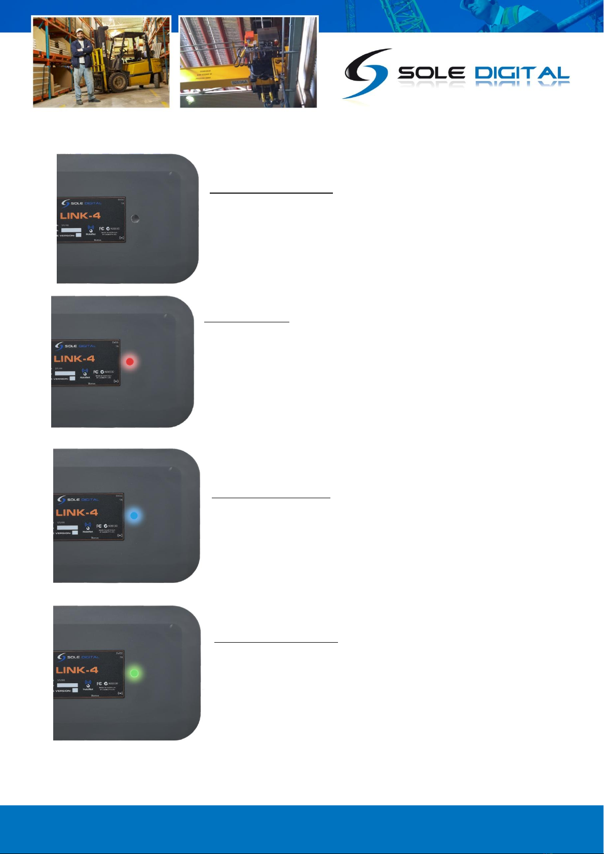
4.2 LED Indicator Lights
On the face of the Link-4 is one LED indicator light, which will either display a Green, Red, or Blue
light. Each of the colours will indicate different situations, so please examine the below diagrams for
a reference guide to each of the light indications.
© CASWA Pty Ltd –2017 9 | Page
NO LIGHT ON = No Power
If there is no power running to the unit, check your adaptor is the
correct voltage and that there is power running to your Link-4
RED LIGHT = Fault
There is some fault in the unit, whether it is not connected to a device
yet, or is failing to find a 4G signal to broadcast on. If you see a Red
Light upon startup though, this will be normal. Please refer to section
4.3 for further guidance on the startup procedure for the Link-4
BLUE LIGHT = Connecting
When the Link-4 is displaying a Blue light this means the device is
attempting to connect with a nearby Hoistnet device via Bluetooth.
GREEN LIGHT = Connected
When the Link-4 is displaying a Green Light it means that a
connection has been made and the device is operating as per normal.

© CASWA Pty Ltd –2017 10 | Page
4.3 STARTUP PROCEDURE
Upon connecting the Link-4 to power the device should go through the following steps. If you
disconnect Link-4 from its power source, the device will recycle through these steps. If the device
remains in the RED phase for longer than 3 minutes, check to make sure your Link-4 has a 4G signal
and is within range of the Hoistnet device you are attempting to connect to.
Figure 5: Link4 Startup Timeline

© CASWA Pty Ltd –2017 11 | Page
5SIM CARD AND 4G CONNECTIVITY
Whilst your Link 4 connects to Hoistnet devices via Bluetooth, it connects to the cloud and the
outside world via a 4G signal using the inbuilt SIM Card. The SIM card will be inserted and set up by
SoleDigital before shipping, so it is important to let the Sole Digital staff know what county your
Link-4 will be operating in before shipping, so a corresponding SIM card can be inserted into the unit
to connect with your countries local telephone network.
5.1 SIM CARD REFRESH
The Link-4 comes with an annual subscription fee from Sole Digital, with this subscription fee being
used to fund and replenish credit on the SIM Card to maintain operability. As long as the annual fee
is up to date, you will not need to do anything further to maintain the Link-4’s connection with the
outside world, and Sole Digital will be responsible for making sure the SIM card remains in
operation. If your SIM card does stop functioning though, it may mean that your subscription fee
has not been paid. In this case please confirm with your accounts team that they have processed the
annual invoice, or contact Sole Digital to determine the cause of the fault.
Note: If you have purchased your Link 4 in one country, but are moving to another country and are
hoping to use the Link-4 in that country you must contact Sole Digital so the appropriate settings
adjustments can be made. In most cases, this change can be executed remotely by Sole Digital, but in
some cases, you may be required to switch out the SIM card inside the device. For more advice on
this process please speak to a member of the Sole Digital technical team.
6SETTING UP REAL-TIME ALERTS ON YOUR DEVICE
The Link-4 allows you to receive real-time notifications for several different events including
overload pulls, sidepulls and transient spike overloads. These alerts will be measured by your devices
like a Liftlog or Maxout, analysed and then sent to your designated email by the Link-4. Depending
on the type of device you are receiving data from you will either enable the alerts via the Field
Service Utility Software (FSU) or via the Sole Digital Web Portal. Make sure to identify the device you
will be receiving the load signal from and use the corresponding chapters of this manual to properly
institute it. This will mean using Step 6.1 for the Web Portal set-up, or Step 6.2 for the Fsetup, for
which device corresponds with which method please read the first paragraph of the 2 steps.

© CASWA Pty Ltd –2017 12 | Page
6.1 WEB PORTAL SETUP
IMPORTANT: The Web Portal Setup Only applies to LIFTLOG and ACCESSPACK products, if you are
trying to set up alerts from a different device please skip to step 6.2.
For this method you will need to grab your RFID card reader, USB Type B Cable, and Software
Licence Access Pack Card. The Software Licence card is different to your regular Accesspack card,
and can be identified via the words “Software Licence” along the right hand side, as demonstrated in
the diagram below.
Figure 6: RFID Reader and USB-TYPEB Cable (Left)
AccessPack Software Licence Card with Distinguishing Feature Highlighted (Right)
6.1.1 Plug-In your RFID Card reader into a PC
6.1.2 Once powered up place your Software Licence card into the
card reader, as indicated by the diagram on the right.
Note: If the light on the RFID doesn’t turn Green upon presentation of your card it
may mean that you have not downloaded the CASWA.Cardreader software. If this
is the case please proceed to the next step. If your card does register right away
feel free to skip to step 6.1.5.

© CASWA Pty Ltd –2017 13 | Page
6.1.3 Downloading the CASWA.CardReader software
First, you will need to visit the Sole Digital website to download the card reader software, the
software can be found at >> https://www.soledigital.com.au/AccessPack.html (1). You will need to
scroll down the page and click on the [Downloads] tab (2) and then proceed to the [Card-reader-
setup] link (3). Once you double-click on the link the program will begin downloading.
Figure 7: How to Download the Card Reader Software
6.1.4 Installing the Software
Upon opening the [Caswa.CardReader.Service.Installer] prompts will appear to install the program,
simply follow the prompts. Once installed you will then need to restart your computer to complete
the process.
Upon restarting your computer head back to the Sole Digital Website >> >>
https://www.soledigital.com.au/AccessPack.html and then click on the Login tab near the top of the
page (4).

© CASWA Pty Ltd –2017 14 | Page
6.1.5 Accessing the inspector
This stage of the process is done via the SoleDigital website portal >>
https://www.soledigital.com.au/AccessPack.html, via the [Login] tab on the page. The portal login
can be found near the top of the Sole Digital website as indicated by Step (4) in Figure 7.
With an RFID reader plugged into the computer and having clicked on the [Login] page, you will be
directed toward a webpage prompting you to swipe your AccessPack card. Once you placed your
card onto the RFID reader as indicated in step 6.1.2, the page will then automatically direct you into
the inspector interface. Once open the inspector should take around 10 seconds to populate, and
the light on your RFID reader will begin to oscillate between Green and Red. Once the inspector has
been populated with your devices in the left-hand side panel, remove your card from the RFID
reader. The light at the top of the reader will now turn Red.
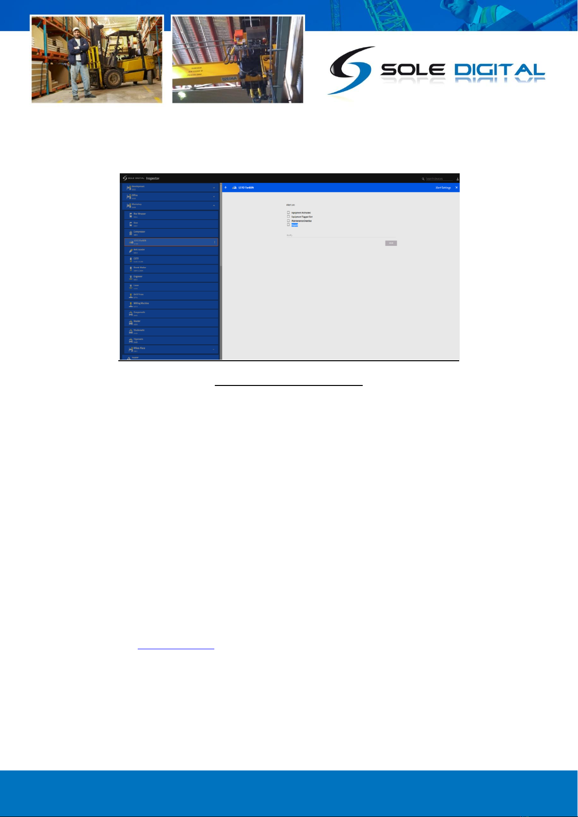
On the inspector interface, you will see all of your allocated devices populated in the left-hand
column, like the example below. In our example here we are trying to make adjustments to our
[LS12 Forklift] located in our [Workshop]. On the dropdown menu select your device's location, and
then click on the device you are trying to receive alerts from. Upon selection, the devices options will
appear in the main window. To set up alert alerts you will then need to click on the [Alert Settings]
icon.
The alert settings button will then bring you to the [Alert Settings Menu]
Figure 8: The Inspector Interface
© CASWA Pty Ltd –2017 15 | Page
Figure 9: The Alert Settings Menu
6.1.6 Picking your Settings
In our example here our alert settings menu has 4 options:
-Equipment Activated: To receive an email when the equipment is activated.
-Equipment Tagged Out: To receive an email when an operator turns off the equipment for
maintenance.
-Maintenance Overdue: To receive an email when your equipment is overdue for
maintenance or inspection
-Impact: To receive an email when your equipment (a forklift in our example) receives a G-
Force shock through a collision.
Note: Impact Detection may not be available on your device depending on which device you have
installed.
Simply click each scenarios checkbox you wish to receive notifications about. You will need to then
select an email for the notification to be sent to, in our example, we have chosen to send our
notifications to tech@caswa.com. So if any of our alerts are triggered on our example forklift here,
our technical team will be sent an email with the details of the event.
Once you have designated a receiving email and checked the appropriate boxes, then press the
[Save] button below and the changes will be implemented in the system.
© CASWA Pty Ltd –2017 16 | Page
6.2 FIELD SERVICE UTILITY (FSU) ALERT SETUP
IMPORTANT: The FSU Setup Only applies to MAXOUT, SIDEWISE and HIBEAM products, if you are
trying to set up alerts from a different device please skip to step 7.
The Link-4 allows you to receive real-time notifications for several different events including
overload pulls, sidepulls and transient spike overloads. These alerts will be measured by your devices
like a Liftlog or MaxOut, and sent to your designated emails via the Link-4. Make sure to identify the
device you will be receiving the load signal from, and either uses Step 6.1 for the Web Portal set-up,
or Step 6.2 for the FSU setup.
For our example in this step we will be setting Overload notifications from a Maxout device, using
the Link-4 to send the notifications to our tech team’s email address. For the Maxout, Sidewise and
Hibeam devices this process is set up through Sole Digitals Field Service Utility software. If you
already have the FSU installed on your computer, feel free to skip to step 6.2.2. If you haven’t
currently got the FSU installed on your computer continue on step 6.2.1.
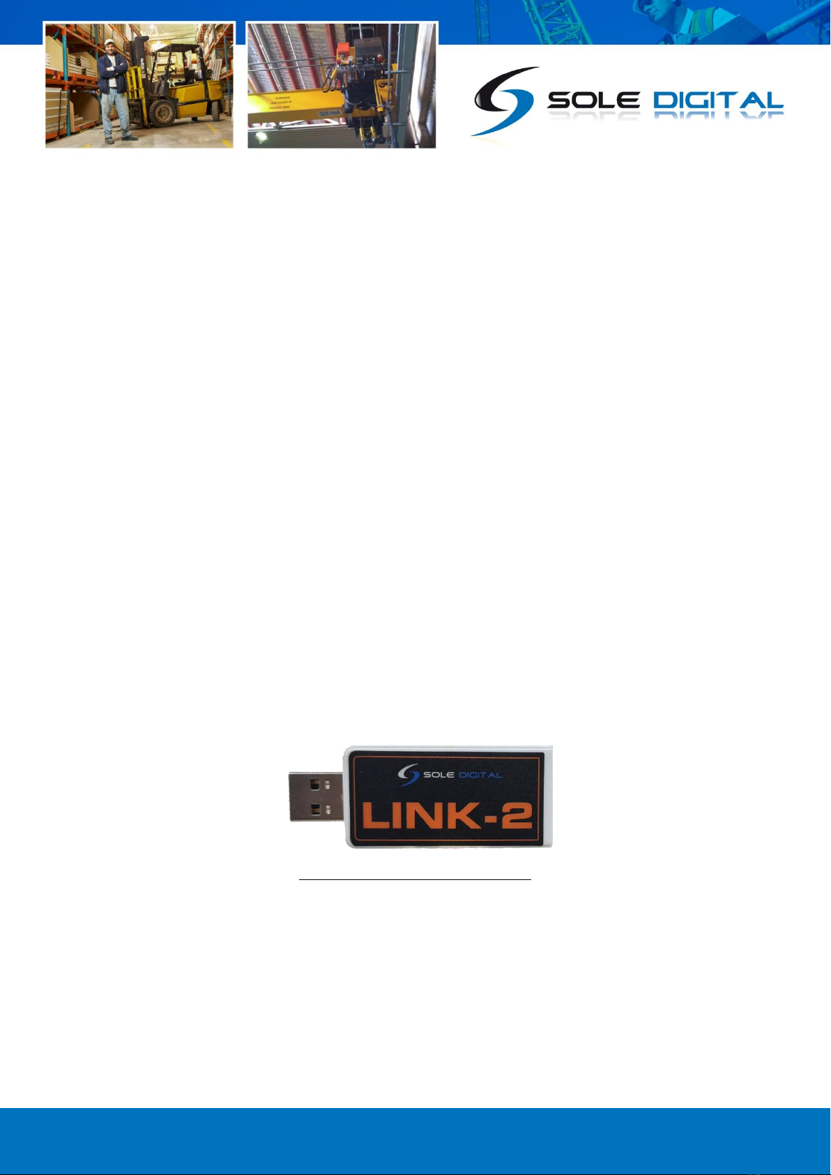
6.2.1 Installing the Field Service Utility (FSU)
Most Sole Digital products are designed to be commissioned via our FSU software using a laptop
computer, so for this process, you will need to make sure you have a computer ready to go. You will
also need a CASWA LINK-2 Bluetooth Modem (Pictured Below in Figure 10) and the Field Service
Utility (FSU) software application, version 17.1 or higher, loaded on a laptop.
Figure 10: A Link2 Bluetooth Modem
To download the FSU software you will need to visit the SoleDigital website, download the FSU
program and install it onto your Windows PC. For the program to function correctly you will need to
make sure your PC is operating with Windows 7 or above, if you require a version of the FSU
program that is compatible with operating systems before Windows 7 please contact the SoleDigital
team directly as universal support is no longer provided for operating systems that pre-date
Windows 7.
© CASWA Pty Ltd –2017 17 | Page
The FSU software can be downloaded from the [Download] tab on the following link >>
https://www.soledigital.com.au/MaxOut.html
Note: You should check this location periodically for updates.
6.2.2 Launching the application
Once the program has been installed onto your computer, double-click on the FSU program icon:
.
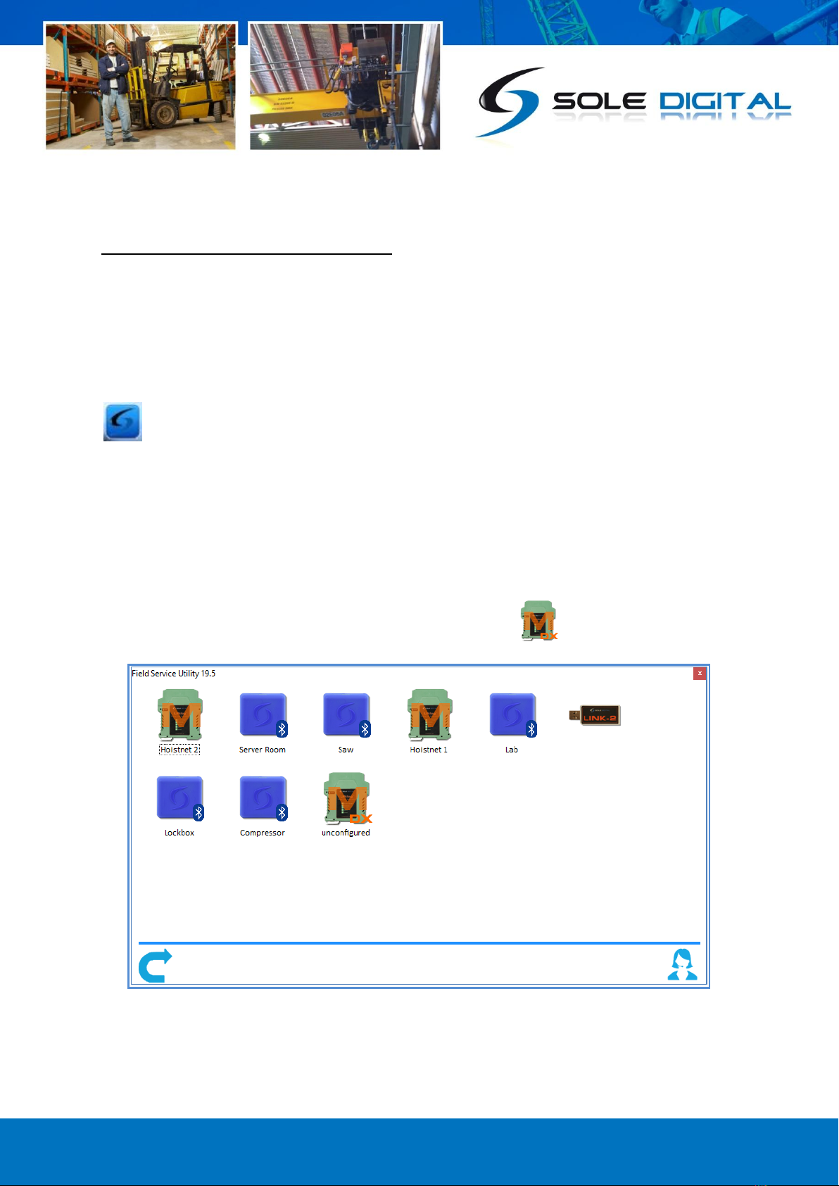
6.2.3 Connecting to the MaxOut
Upon opening the FSU program will automatically use the Link-2 to scan for all of the Bluetooth-
enabled devices within range. This process takes approximately 10-20 seconds, and once completed
your devices will populate the program with a list of all your SoleDigital devices like in the example
diagram below. In our example here MaxOut’s are depicted by a icon.

© CASWA Pty Ltd –2017 18 | Page
If the particular MaxOut unit you are trying to work on is not found, ensure it is powered up and
press to repeat the search.
Note: The Bluetooth link between the Laptop and Maxout is within approximately 100m.
If you require live support for any of Sole Digital products, either go to our website or open a remote
support session, by pressing the icon.
Otherwise, select the Maxout you wish to receive notifications from by double-clicking on the
desired icon.
When you click on the MaxOut unit you are tethering your Link-4 too it should bring up the settings
interface for the unit. If an interface like the example in step 6.2.5 appears, then you can skip past
step 6.2. If the MaxOut does not bring up that interface it likely means you will require a firmware
update for your MaxOut, in which case please continue onto step 6.2.4.
6.2.4 Managing Firmware
Firmware updates are not always required and you should only be updating your firmware if you:
a) Specifically want a new feature that is only available in later versions;
b) Are experiencing a problem that has been rectified by a later version;
c) Are experiencing a problem and need to roll back to an earlier firmware version that didn't
cause the problem you are experiencing; or
d) Have been specifically instructed to do so by your MaxOut supplier.
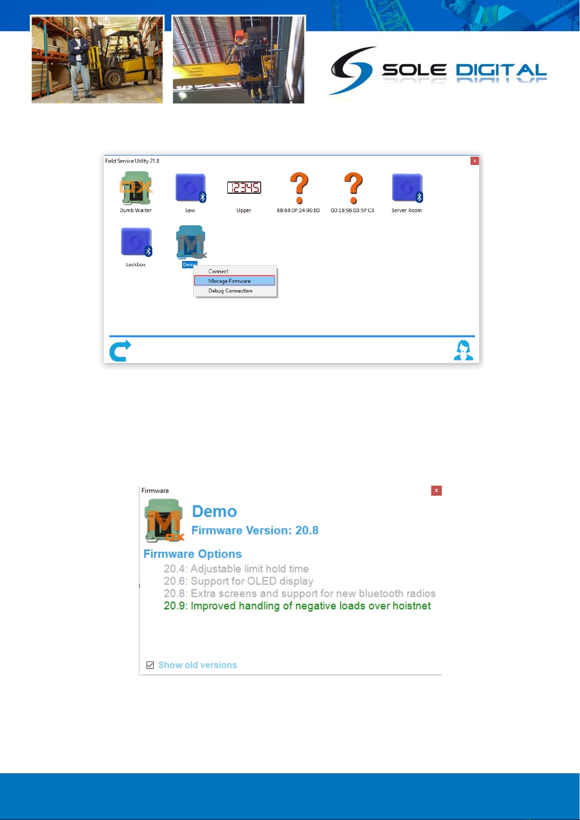
To check for new firmware versions or to access old firmware versions, return to the Device Display
screen and right click the desired equipment icon. Select 'Manage Firmware'.
© CASWA Pty Ltd –2017 19 | Page
A new window will pop up showing the FSU software connecting to the device. When this is
complete, the window will show the name of the device, its current firmware version and a list of
newer firmware that is available for the device.
If you need to roll back to an earlier version, check the 'Show old versions' box in the lower-left
corner of the window.
© CASWA Pty Ltd –2017 20 | Page
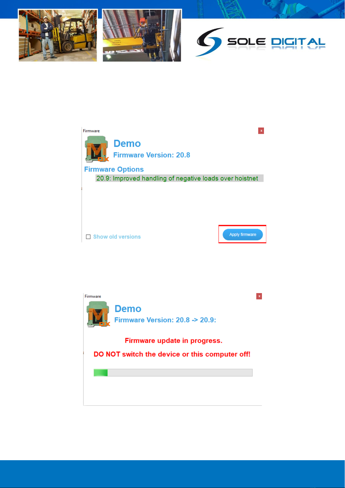
Select a firmware version and then press the <Apply firmware> button that appears in the lower
right corner of the window:
The display will change to the following:
This manual suits for next models
1
Table of contents
Other Sole Digital Gateway manuals

Popular Gateway manuals by other brands


Discovery Telecom
Discovery Telecom DTT PRI GSM Ingate user manual

IntesisBox
IntesisBox IBOX-BAC-MBM Installation sheet

Juniper
Juniper BX7000 Hardware guide

Berker
Berker 75710016 quick guide

MVC-Data
MVC-Data AccessZone GC1000 Series installation manual

DELTA GROUP
DELTA GROUP EnOcean O3-DIN Application guide