Solglass Solartrix 1200-400 Series User manual

Solar PV module installation
manual
Version
Number
:
2020-A1
Issued
Date
:
2020-4-23
Amended
Date
:
--
Corporation:Nanjing
Solglass
Science&Technology
Co.,
Ltd
.
The manual applies to the following product
models
:
Solartrix 1200-400-xx
Note:“xx”
r
e
p
r
e
s
e
n
t
s
t
h
e
s
p
ec
i
f
i
c
po
w
e
r
o
f
t
h
e
m
odu
l
e
,
in steps of 5
W
.
Important safety Tips
This installation manual provides Nanjing Solglass Science&Technology Co. , Ltd.
(Hereinafter referred to as "SOLGLASS”) photovoltaic modules (hereinafter referred to as
"modules") of the installation and safe use of information. All safety aspects of this
guide,precautions and local regulations should be followed during modules installation and
routine maintenance.Precautions and local regulations.
Installing module system requires expertise and knowledge, it can only be done by
qualified personnel. Please read this installation manual carefully before installing and using
modules. The installer shall be familiar with the mechanical and electrical requirements of
the system. Please keep this manual for future maintenance and repair or when the modules
need to be sold or processed.
Please contact the SOLGLASS after service department for more explanation.
1

2
1. Introduction
First of all, thank you very much for choosing the SOLGLASS pv module.
This installation manual contains important electrical and mechanical installation information that
you should read firstly before installing the SOLGLASS PV modules. In addition, the manual
contains some additional security information that you must be familiar with. All of the contents of
the manual are part of SOLGLASS’intellectual property which comes from SOLGLASS’long term
of technical exploration and experience.
This installation manual, either express or implied, is not warranty letter, Where no provision is
made for module losses, damage or other expenses arising from or the installation or relating to
the installation, operation, use, or maintenance of the module, a compensation scheme shall be
provided. If the use of module caused by the infringement of patent rights or the rights of third
parties, SOLGLASS does not assume any relevant liability. SOLGLASS reserves the right to
change the product description and this installation manual without prior notice.
Customer doesn’t comply with the requirements set out in this manual will result in the failure of
the limited warranty at the time of sale. At the same time, the recommendations in this manual
are designed to improve the security of modules during installation and are tested and proven.
Please provide this manual to pv system owners for their reference and advise them of all
relevant safety, operation and maintenance requirements and recommendations.
2. Rules and regulations
Mechanical and electrical installation of pv modules shall be governed by relating regulations,
including electrical, building and electrical connection requirements. These regulations is
different according to the different location of the installation, such as building roof installation,
on-board applications, etc. . Requirements may be also different depending on the installation
system voltage, use of DC or AC. Please contact the local authority for details.
3
3. Safety precautions
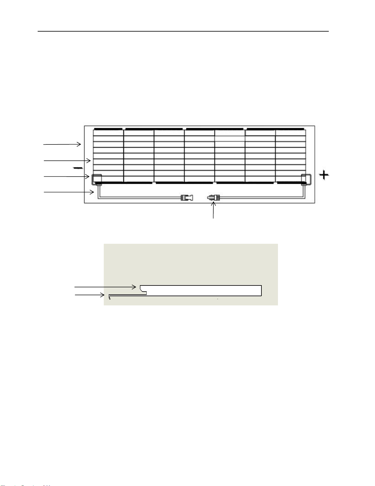
solar module structure and component description
Solartrix 1200-400-xx
4
3
2
1
5
Mounting
fitting
6
7
1. cable 2.junction 3.cells 4. solar glass 5.connector 6.connecting slot 7.connecting hook

4
3.1Routine Safety
Solglass's module design complies with international IEC 61215 and IEC 61730 standards, and its
application rating is Class A: The module can be used for systems with voltage higher than 50V or
240W DC. And the module has passed IEC 61730-1 and IEC 61730-2, the module meets the
requirements of Class II.
The overall fire rating of the final structure needs to be considered when the module is installed for
use on the roof. At the same time, the overall maintenance is also needed to be considered. Rooftop
PV systems can only be installed after an evaluation by a construction expert or engineer, with formal,
complete structural analysis, and proven to be able to withstand additional system support pressure,
including the pv module's own weight.
For your safety, please do not work on the roof without safety precautions including but not limited to
fall protection, ladders or stairs and personal protective equipment.
For your safety, do not install or handle modules under bad conditions, including but not limited the
high winds or gusts, wet or sandy roofs.
3.2 Electrical Safety
PV products generate direct current in the presence of sunlight, so touching the the wire metal of the
module can be a risk of electric shock or burn. A 30 volt DC or higher voltage can be fatal.
The module also generates voltage without connecting the loads or external circuit. Use an insulated
tool and wear rubber gloves when operating module in the sunlight.
There's no switch on the pv module. The PV module can only be stopped by removing it from the
light or by shielding it with cloth, cardboard, or a completely opaque material, or by placing the front
side of the module on a smooth, flat surface.
In order to avoid the danger of electric arc and electric shock, do not disconnect the electrical
connection under the load. The wrong connection can also cause arcing and electric shocks.
Connectors must be kept dry and clean to ensure that they are in good working condition. Do not
insert a metal object into the connector, or otherwise make an electrical connection.
The power generated by the module may be higher than the nominal rating on the name plate. The
rated output power of the factory test calibration is measured under the module standard test
conditions (module standard test conditions: 1000 W / M2 irradiance, 25 °C ambient temperature,

5
AM1.5 atmospheric mass) . The surrounding snow and water reflect more light, causing an increase
in current and output power.
In addition, at low temperature, the voltage and power of the module will increase correspondingly.
If the module glass or other material damage, please wear a personal protective device, separate
the component from the circuit.
Do not touch the module if it is wet. Except when cleaning components, but in accordance with the
requirements of the manual cleaning components.
Never touch a wet connector without wearing a personal protective device or rubber gloves.
Do not use a mirror or magnifying glass to manually focus the sunlight on the module.
3.3 Operation Safety
During transportation and storage, do not open SOLGLASS's package unless the package has
arrived at the installation site.
Please protect the packing from damage. Do not drop the package directly.
Do not stack modules above the maximum stack number printed on the package.
Please put the packing box in a cool and dry place before unpacking the packages.
To open SOLGLASS's box, follow its instructions.
In no case shall the module be lifted by holding on to the junction box or wire; never stand or
move on the module.
Never drop one module onto another.
In order to avoid breakage of the glass, do not place any weight on the module glass. When
placing a module on a flat surface, handle it with care, especially in corners.
Do not attempt to disassemble the module or remove the nameplate of the module or parts on
the module .
Do not paint or apply any other adhesive to the surface of the module;
Do not self-replace broken glass of the module.
Only work in dry conditions and only use dry tools.
Do not operate the module when it is wet, unless appropriate shock protection equipment is
worn.
When stacking storage modules outdoors, always keep the front side of the module facing down
and prevent water from entering the module and damaging its connector.
3.4 Fire proofing safety
Fire rating:Class C

6
Consult local laws and regulations before installing modules to comply with building fire proofing
safety requirements.
Different roof structure and installation methods will affect the building's fire proofing safety
performance. If the module is not properly installed, it may cause a fire.
Use the appropriate components such as fuses, circuit breakers, and ground connectors as required
by local regulations. Do not use modules if flammable gas is present nearby.
4. installation conditions
4.1 Installation Location and working environment
The module can only be used on earth under 2000m altitude, not in space.
Modules can not be installed and used in excessive environment such as excessive salt, fog,
hail, snow, sand, smoke, air pollution, active chemical vapor, acid rain, soot, etc.
When there is heavy snow, extremely cold, strong wind or near water, close to salt fog on the
island or desert environment, please use appropriate protective measures to ensure the reliability
and safety of module installation.
Components must be installed on suitable buildings or other suitable locations (eg. Ground,
garage, building facade, roof, PV tracking system) and components can not be installed on any
type of mobile vehicle.
Do not install modules on the location where there is a risk of flooding.
It is recommended that the module is needed to be installed in a working environment with a
temperature of-40 °C to 40 °C, which is the monthly maximum and minimum temperature at the
location of the installation. The limit working environment temperature of the module is-40 °C to
85 °C.
Ensure that the wind or snow pressure on the module after installation does not exceed the
maximum allowable load.
module need to be installed in a no shaded area throughout the year.
Ensure that there are no obstructions that may block light at the location where the module is
installed.
If the module is installed in a place with frequent lightning activity, the module must be protected
against lightning strikes.
Do not install modules in a place where flammable gases may be present. The SOLGLASS’s
module shall not be installed in a place where strong corrosive substances such as salt, brine, or
any other material may corrode the modules, affecting its safety or performance.
SOLGLASS’s module have passed the salt spray corrosion test of the IEC61701, but corrosion
can occur at the edges of the components where they are connected to the bracket, or where
they are connected to the ground.

7
SOLGLASS recommends that when the module is installed by the sea, it needs to be treated to
prevent corrosion at the installation site.
4.2 Inclination selection
Installation angle of module: The angle between the surface of the module and the horizontal
surface. When the module is facing the sun, the module gets the maximum power output.
In the northern Hemisphere, module should preferably face south, in the southern Hemisphere,
module should preferably face north.
For detailed installation angles, following the standard module installation guidelines or getting
advice from an experienced PV module installer.
When the module is installed on the roof, the angle of inclination shall not be less than 5°to
maintain the corresponding fire protection level.
5. Mechanical installation
5.1 Routine requirement
Make sure that the mounting method and bracket system are strong enough to withstand all
predetermined load conditions, which is a guarantee that the bracket installer must provide.
Mounting brackets must be tested and tested by a third party tester with static mechanical analysis
capability, using local national or international standards or equivalent standards. module mounting
brackets shall be constructed of durable, corrosion resistant, UV resistant materials. The module
must be securely mounted on the mounting bracket.
When the module is mounted on a bracket parallel to the roof or wall.The minimum gap between the
module and the roof or wall surface is 2cm. Air Must be allowed to circulate to prevent module wiring
damage. Do not punch holes on the module, otherwise the module warranty will invalid.
Before installing module on the roof, make sure the building is suitable for installation. In addition,
any penetration through the roof must be properly sealed to prevent leakage.
When dust falls on the surface of the module, it will affect the power output of the assembly.
SOLGLASS recommends installing the module at an angle more than 5 degrees so that the dust
can be easily carried away by rain when it rains.

8
The design static load on the module is 1600Pa on the back and 3600Pa on the front .The safety fac
tor is equal to 1.5.The maximum static load on the module is 2400Pa on the back (equal to wind pres
sure) and 5400Pa on the front (equal to snow pressure) .
5.2 Installation method
The connection of the module and the bracket system shall be made by using the above-mentioned
mounting connectors to form a complete system for installation. The installation component must be
based on the following example, not complying with the following installation requirements may
result in a warranty invalid.
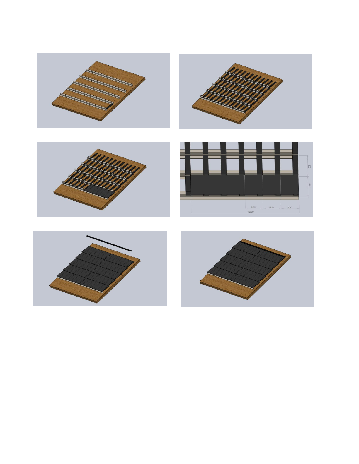
5.2.1Install module by link channel
Please use the link channel provided by SOLGLASS, which are arranged on the roof bracket
through the slot, and then place the module on the connecting hook, each link channel is 20 cm
apart from each other, evenly arranged on the roof bracket, the top and bottom modules are aligned.
After installation, the top is fixed with the top bracket. The diagram is as follows:
Link channel
9
Installation steps
6. Electrical installation
6.1 Electrical property
There is a tolerance between the nominal values of modules such as Isc, Voc and Pmax
under standard test conditions, perhaps the value is relatively higher compare to the value
obtained under component standard test conditions. Therefore, in the determination of
photovoltaic system accessories, such as rated voltage, wire capacity, fuse capacity and
module power output and related parameters, the relating short current and open voltage
amplify 1.25 times can be applied.
Under normal conditions, a photovoltaic module is likely to experience conditions that produce
higher current and/or voltage than reported at standard test conditions. Accordingly, the values
of Isc and Voc. marked on this PV module should be multiplied by a factor of 1,25 when
determining component voltage ratings, conductor current ratings, and size of controls (e.g.
inverter) connected to the PV output.
Electrical Characteristics
Module Type Solartrix 1200-400-55 Solartrix 1200-400-60
Maximum Power-Pmax(W)55 60
Maximum Power Voltage-Vmp(V)34.55 34.77
Maximum Power Current-Imp(A)1.60 1.73
Open Circuit Voltage-Voc(V)41.20±4% 41
.
23
±
4%
Short Circuit Current-Isc(A)1.83±5% 1
.
87
±
5%
Power Tolerance
±
3%
Maximum System Voltage(VDC)1000
Maximum Series Fuse Rating(A)3
Operating Temperature(°C)-40~+85
Pmax Temperature Coefficient(%/°C)-0.40
Voc Temperature Coefficient(%/°C)-0.31
Isc Temperature Coefficient(%/°C)0.05
STC: lrradiance 1000 W/m2 module temperature 25°C AM=1.5, Power measurement tolerance: +/-3%
Mechanical Specifications
External Dimension 1200*400*6 mm
Weight 6.6Kg
Solar Cell Mono 31.35x156.75 mm(63pcs)
Glass to Glass 2.5 mm tempered glass, low iron
Junction Box IP67
Output Cable 4.0 mm2,cable length:900 mm
No more than 2.5% peak power degradation in 1st year;
No more than 0.7% peak power degradation in coming 24
years;
Free from defects of materials and workmanship for 12
years.
Connector
Maximum Snow Load 5400 Pa
Maximum Wind Load 2400 Pa
Hail Resistance Max. Ø 28 mm,at 23 m/s
10

11
When the modules are connected in a series, the final voltage is the sum of the individual
module, and when the modules are connected in parallel, the final current is the sum of the
individual module, as shown below. The modules with different electrical parameters cannot
be connected in a series.
Series connection
Paralleling connection
Series and paralleling connection
Diode Over current protector Connector

12
The maximum number of components that can be connected in series must be calculated in
accordance with the requirements of the relevant regulations, the open-circuit voltage shall not
exceed the maximum system voltage value specified by the component (According to the safety
test of IEC 61730, the maximum system voltage of the SOLGLASS’s modules is DC1000V)
If reverse current may flow through the module exceeding the maximum fuse current of the
module, the module shall be protected by overcurrent protecting device that it has the same
specification. If the number of parallel connections is more than or equal to 2 strings, there must
be an overcurrent protection device on each string.
6.2 cable and connecting
In the design of cables and connections, assemblies, field connections use sealed junction
boxes of Class IP67 to provide protection against environmental impacts for conductors and
their corresponding connections, and to provide touchable protection for uninsulated parts. The
junction box has well-connected cables, wires and protective Class IP67 connectors. These
designs are convenient for connecting modules in series. Each module has two wires
individually connected to the junction box, one positive and one negative. The two modules can
be connected in series by inserting a positive terminal at the other end of a module wire into the
socket of the negative terminal of an adjacent component.
Field connection cables must meet the component's maximum short circuit current usage, and
SOLGLASS recommends that installers use only light resistant cables that meet PV DC
requirements in PV systems, with a minimum diameter of 4mm².
Minimum Standard for the cable
Testing Standard
Wire size
Temperature Rating
EN 50618:2014
4mm2
-40℃to +85℃
When the cable is fixed to the bracket, it is necessary to avoid mechanical damage to the cable
or module. Do not apply pressure to the cable. For cables that are secured in the proper way,
installer must use special light-resistant cable, wires and wire clips to fix the cable to the bracket.
Although the cable is light and water resistant, avoid direct sunlight and water immersion.
6.3 Connecting
Please keep the connector dry and clean. Make sure the connector nut is in a tight status before
connecting. Do not connect connectors when the connector is wet, soiled, or otherwise. Avoid
direct sunlight and immersion of connectors in water. Avoid connector landing on the ground or
roof.
The wrong connection could create an electrical arc and shock. Please check that all electrical
connections are reliable. Make sure all the connectors with locks are fully locked.

13
6.4 The bypass diode
Recommended diode:20SQ045 of Zhejiang Zhonghuan Sunter PV Technology Co.,Ltd.
SOLGLASS's solar module junction box contains the bypass diode and is parallel connected to
the cells string inside the module. When the hot spot occurs locally, the diode will pass only
current through the non-hot spot cell, limiting the module's heat and performance loss. Note that
the bypass diode is not an over current protection.
When you know or suspect a diode failure, contact SOLGLASS for installation or system
maintenance. Please do not attempt to open the junction box of the module.
7. Operation and Maintenance
The modules must be inspected and maintained regularly, especially during the warranty period,
which is the responsibility of the user and notify supplier within two weeks if any module is found
to be damaged.
Dust, such as industrial waste water and, bird droppings, deposits on the glass surface of the
module reduces its power output and may cause regional hot spots. The extent of the effect
depends on the transparency of the waste, and the small amount of dust on the glass affects
absorbing the intensity and uniformity of sunlight, but is not dangerous, and the power is usually
not significantly reduced.
There must be no environmental impact factors, such as the presence of other modules, module
system bracket, bird presence, large amounts of dust, soil, or vegetation that cast a shadow over
the modules and obscure some modules or all modules while they are in operation, resulting in a
significant reduction of output power. SOLGLASS recommends that the surface of the
component not be obscured at all times.
As for the frequency of cleaning, it depends on the dirt accumulates level . Under normal
circumstances, rainwater would clean the surface of the modules, which would reduce the
frequency of cleaning. SOLGLASS recommends using a damp, water soaked sponge or a soft
cloth to clean the glass and surface. Do not use detergent containing alkali or acid to clean
modules.
14
7.1 Visual inspection of modules
Visual inspection of the modules of the appearance of defects, especially
1, the module glass broken.
2. Corrosion of the welding at the main busbar of the cell : Due to during installation or
transportation, the insulating material is damaged, causing moisture entering into the module.
3. Checking the module if any burn marks inside.
7.2 Inspection of connectors and cables
It is recommended that preventive inspections be carried out every six months, as follows:
1. Check the tightness of the connectors and make sure whether the cable connection is secure.
2. Check the junction box to see if the sealant is cracked or has gaps.
8. Others
External or otherwise artificially concentrated sunlight shall not be directed onto the front or
back face of the PV module.
Meaning of crossed –out wheeled dustbin:
Do not dispose of electrical appliances as unsorted municipal waste, use separate collection
facilities. Contact your local government for information regarding the collection systems available.
If electrical appliances are disposed of in landfills or dumps, hazardous substances can leak into
the groundwater and get into the food chain, damaging your health and well- being. When
replacing old appliances with new ones, the retailer is legally obligated to take back your old
appliance for disposals at least free of charge.
9. Ground/earth the modules
Our modules don’t need to be grounded, but the metal brackets (if use) which support the
modules must be grounded.
This manual suits for next models
2
Table of contents
Popular Solar Panel manuals by other brands

Sharp
Sharp NU-AH370 installation manual

Beretta
Beretta SC-F25/1 installation instructions

NURZVIY
NURZVIY SolarEpoch 200 user manual

Viessmann
Viessmann VITOSOL-F installation instructions

Buderus
Buderus SKS 4.0 Series installation instructions

Viessmann
Viessmann Vitosol 200-T Service instructions for contractors


