Omnitracs TT210 Instruction Manual

Copyright © 2014-2015 Omnitracs, LLC.
All rights reserved.
Omnitracs is a trademark of Omnitracs, LLC. All other trademarks are the property of their respective
owners.
Omnitracs endeavors to ensure that the information in this document is correct and fairly stated, but
Omnitracs is not liable for any errors or omissions. Published information may not be up to date, and it is
important to confirm current status with Omnitracs.
This technical data may be subject to U.S. and international export, re-export or transfer (export) laws.
Diversion contrary to U.S. and international law is strictly prohibited.
Omnitracs, LLC
717 N. Harwood Street, Suite 1300
Dallas, TX 75201
U.S.A.
TT210 Solar Panel Replacement
Guidelines
80-J8159-1 Rev. D
September 2015

80-J8159-1 Rev. D MAY CONTAIN U.S. AND INTERNATIONAL EXPORT CONTROLLED INFORMATION 2
Revision history
Revision Date Description
A May 2014 Initial release
B September 2014 Update re-assembly instructions
C September 2014 Removed "Restricted" verbiage from Copyright page and footers
D September 2015 Updated copyright dates verbiage for Copyright page and footers

80-J8159-1 Rev. D MAY CONTAIN U.S. AND INTERNATIONAL EXPORT CONTROLLED INFORMATION 3
Contents
1 TT210 Solar Panel Replacement Guide....................................................................4
1.1 Required Tools:..........................................................................................................................5
1.2 Required Materials:....................................................................................................................5
1.3 Disassemble: Battery and Bottom Cover...................................................................................7
1.4 Dis-Assemble: Main CCA (Circuit Card Assembly)...............................................................11
1.5 Removal and Disposal of Solar Panel Assembly.....................................................................13
1.6 Solar Panel Assembly Sequence..............................................................................................15
1.7 Assemble Main CCA on Housing............................................................................................19
1.8 Bottom Cover Assembly..........................................................................................................23
1.9 Battery Cover Assembly..........................................................................................................25

80-J8159-1 Rev. D MAY CONTAIN U.S. AND INTERNATIONAL EXPORT CONTROLLED INFORMATION 4
1 TT210 Solar Panel Replacement Guide
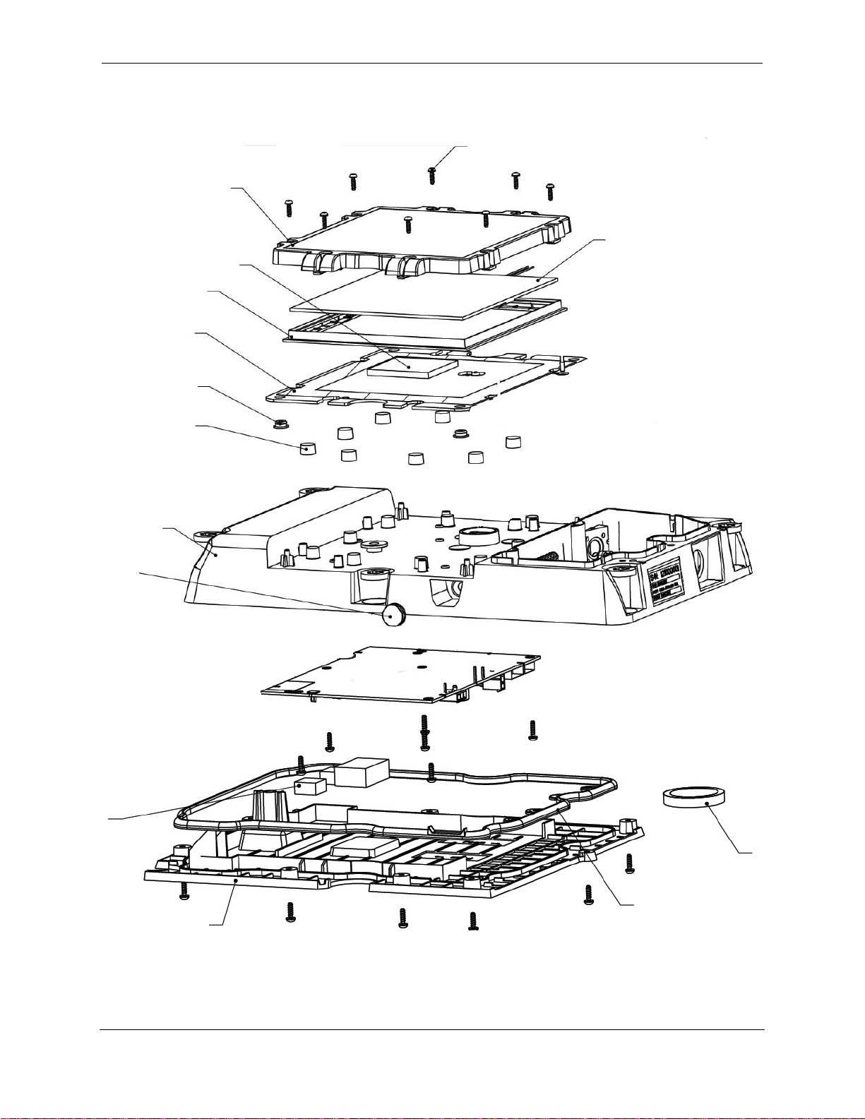
This document provides general guidelines to successfully remove and replace the solar panel assembly
for the Omnitracs Trailer Tracks 210 Unit (TT210).
ATTENTION Replacing the solar panel assembly will void the TT210 warranty.
CAUTION: Electrostatic Discharge Control (ESD)—Devices are susceptible to damage by electrostatic
discharge.
The solar panel replacement shall be performed at an effective ESD control work station in
accordance with EIA JESD-625 "Requirements for Handling Electrostatic Discharge-Sensitive
(ESDS) Devices" or equivalent.
CAUTION: Use of eye and hands protective wear is recommended.
CAUTION: For the re-assembly process, protective eye goggles and leather gloves are recommended to
safely remove broken glass.
NOTE: Use of electric or power driver during re-assembly process may result in damage to unit.
The recommended process is to hand-tighten the screws with a hand torque driver. The use of
electric torque drivers are permitted provided the user complies with the stated torque values or
damage to the housing screw threads will result and the housing become unusable.
NOTE: Discard fasteners. Screws will be replaced during the re-assembly process.

TT210 Solar Panel Replacement Guidelines
80-J8159-1 Rev. D MAY CONTAIN U.S. AND INTERNATIONAL EXPORT CONTROLLED INFORMATION 5
1.1 Required Tools:
Approved ESD work station
Torx T10 driver bit
Hand screw driver for torx bit
Adjustable torque driver
Cleaning wipes
Isopropyl alcohol
Cotton swabs
Gloves
Brush
Putty knife
1.2 Required Materials:
Solar Panel Replacement Kit, TT210, 65-J8159-1

TT210 Solar Panel Replacement Guidelines
80-J8159-1 Rev. D MAY CONTAIN U.S. AND INTERNATIONAL EXPORT CONTROLLED INFORMATION 6
TT210 Assembly Diagram
NOTE: Components are removed for clarity in this exploded view.
Main CCA
Window
Foam
Gasket
Plate
Shock
Absorber
Silent Boss
Solar Panel
Housin
g
Plug
Foam
Connector
Cover Gasket
Gasket
Foam
Screw, Torx, Pan head

TT210 Solar Panel Replacement Guidelines
80-J8159-1 Rev. D MAY CONTAIN U.S. AND INTERNATIONAL EXPORT CONTROLLED INFORMATION 7
1.3 Disassemble: Battery and Bottom Cover
NOTE: Before performing any rework operation on the unit, remove the battery pack to avoid danger of
an electric short and possible damage to the circuit board.
1. Open the trap access door. Untighten the (5) captive-screws using a screw driver with
Phillips tip type.
Fig. 1. Trap Access Door
2. Carefully unseat the battery from the holder.
Fig. 2. Battery Pack

TT210 Solar Panel Replacement Guidelines
80-J8159-1 Rev. D MAY CONTAIN U.S. AND INTERNATIONAL EXPORT CONTROLLED INFORMATION 8
3. Unplug the battery connector from the unit.
4. Press the connector locking tab as shown in Fig. 3 and simultaneously pull the connector
away.
Fig. 3. Unplug Battery Connector
5. Place both the trap access door and battery aside to reuse them in a later sequence.
6. Place the unit upside down.
7. Remove the bottom cover’s (8) screws, shown in Fig. 4 below. Use a screw driver with torx
bit #10.
Fig. 4. Bottom Cover Screws

TT210 Solar Panel Replacement Guidelines
80-J8159-1 Rev. D MAY CONTAIN U.S. AND INTERNATIONAL EXPORT CONTROLLED INFORMATION 9
8. Slowly lift the bottom cover from the housing. The pressed gasket is the only thing holding
the bottom cover in place at this point. Once detached, set the bottom cover aside.
Fig. 5. Detach Bottom Cover from Housing
9. Hold the bottom cover with your hand and push screws up with your fingers. Take out and
discard the screws.
Fig. 6. Removing Screws from Bottom Cover

TT210 Solar Panel Replacement Guidelines
80-J8159-1 Rev. D MAY CONTAIN U.S. AND INTERNATIONAL EXPORT CONTROLLED INFORMATION 10
10. Place the bottom cover down with the side opposite to the screw locations on top.
11. Remove the gasket located along the edge over the raised guide.
12. Remove the one piece gasket without leaving any gasket particles and discard. Save the
bottom cover to be reused later.
FIG 7. Gasket Removal
13. Inspect the bottom cover component/rib side. Make sure all the screw mountings are not
broken or cracked. It should be totally free of debris or foreign particles. There should be
no moving or loose parts.
14. Verify the (2) foam protectors for the coax connectors are in place and in sound condition.
NOTE: If the foam is pushed in with the connector shape it is acceptable.
Fig. 8. Inspect Foam Protectors
15. Verify the bottom cover is in a clean and undamaged condition.
This completes the bottom cover disassembly sequence.
Gasket
Gasket
Mounting

TT210 Solar Panel Replacement Guidelines
80-J8159-1 Rev. D MAY CONTAIN U.S. AND INTERNATIONAL EXPORT CONTROLLED INFORMATION 11
1.4 Dis-Assemble: Main CCA (Circuit Card Assembly)
1. Place the housing in front of you. Identify the (6) cables connected to the CCA. Unplug all
connectors:
a. Lift the coax connector J4 and J5 by firmly pulling up the connector body with your
fingers.
b. Unlock J19 and J9 by removing the connector upper notch, as shown in Fig. 9, b.
c. Unlock J16 and J23 by pushing down the lock while removing the connector from the
CCA, as shown in Fig. 9, c.
Fig. 9. Removal of All Cable Connections
d. Pull each coax connector straight up while holding the square body on top
b. c. d.

TT210 Solar Panel Replacement Guidelines
80-J8159-1 Rev. D MAY CONTAIN U.S. AND INTERNATIONAL EXPORT CONTROLLED INFORMATION 12
CAUTION: Do not attempt to unplug the connecters by pulling the wires, this may damage the cable. Unlock
each connector by pressing gently but firmly by its lock bar or tab, as shown in Fig. 9, b-d.
2. Remove (6) screws from CCA, using a screw driver with Torx bit #10. Make sure the Torx
bit is fully seated into the screw’s socket before removing the screw. Discard used screws.
Fig. 10. Remove CCA Screws
CAUTION: Before you remove the CCA from the housing, be aware that it is critical for the CCA to be re-
installed in this very same housing. Note that the housing bears the same Serial Number stored in
the CCA that is used in the TT210 application software.
3. Use both hands to unseat the CCA from the housing. Note that the CCA is retained in place
by two guide pins. Lift the CCA firmly and set aside on an ESD safe surface.
Fig. 11. Guide Pins
This completes the Main CCA disassembly sequence.
Guide
Pins

TT210 Solar Panel Replacement Guidelines
80-J8159-1 Rev. D MAY CONTAIN U.S. AND INTERNATIONAL EXPORT CONTROLLED INFORMATION 13
1.5 Removal and Disposal of Solar Panel Assembly.
NOTE: Be careful while handling a broken solar panel. Use leather gloves to avoid injury.
1. Remove (8) screws from solar panel, using a screw driver with torx bit #10. Discard used
screws.
Fig. 12. Remove Solar Panel Screws
2. Holding from each side, unseat the solar panel assembly from the housing. Lift the solar
panel and gasket up slightly until you feel it release from the guide pins.
Fig. 13. Unseat the Solar Panel

TT210 Solar Panel Replacement Guidelines
80-J8159-1 Rev. D MAY CONTAIN U.S. AND INTERNATIONAL EXPORT CONTROLLED INFORMATION 14
3. Carefully discard the window and gasket with the broken glass pieces of the solar panel
into a safe container. Push the parts away from the unit over a trash container.
Fig. 14. Discard Broken Solar Panel and Parts
4. Use a brush to clear the plate and its foam pad of glass residue. Inspect the foam pad and
make sure it is in good condition.
Fig. 15. Brush off Broken Glass from Plate
The Solar Panel
cable goes through
the housing and
plate hole.

TT210 Solar Panel Replacement Guidelines
80-J8159-1 Rev. D MAY CONTAIN U.S. AND INTERNATIONAL EXPORT CONTROLLED INFORMATION 15
5. Clean the entire area of the plate with isopropyl alcohol.
Fig. 16. Clean Solar Panel Plate
This completes the solar panel removal sequence.
1.6 Solar Panel Assembly Sequence
For the next assembly sequence, use the Solar Panel Assembly kit, which includes the following
components:
Solar Panel Window, 50-J7681-P1
Solar Panel, CV90-J8001-P1
Solar Panel Window Gasket, 50-J7676-P1
Screw M3x10, 552-53058-0010 (22)
Bottom Gasket, 50-7672-P1
Gore Vent, 557-45294-0007 or -0009
Alcohol Pad, 800-01788-1182 (2)
Instructions Guide, 80-J862-1
TT210 Re-install Kit, 65-J8023
Silent Block, Gasket, Cover (6)
Screw, Captive, Phillips (5)
Gasket, Foam
Rivet Kit Duraplate

TT210 Solar Panel Replacement Guidelines
80-J8159-1 Rev. D MAY CONTAIN U.S. AND INTERNATIONAL EXPORT CONTROLLED INFORMATION 16
Rivet Kit Non-duraplate
1. Retrieve the Solar Panel Assembly P/N CV90-J8001-P1 as supplied in the replacement kit.
Verify the window, glass panel, and cable are intact and clean.
2. Carefully remove the plastic window to inspect the solar panel with the gasket installation
for proper fit, shape, and orientation.
Fig. 17. Verify the Solar Panel Assembly.
3. Before mounting the solar panel on the plate, place both parts so that the solar panel cable
orientation matches the plate's foam side and feed the cable through the opening.
4. Take the cable with your hand and insert the connector through the aluminum plate
opening.
Top side of
Solar Panel shown
Cable from the
back of Solar Panel
Wires are taped to the
back side of Solar Panel

TT210 Solar Panel Replacement Guidelines
80-J8159-1 Rev. D MAY CONTAIN U.S. AND INTERNATIONAL EXPORT CONTROLLED INFORMATION 17
5. Ensure the solar panel is seated on the top of the aluminum plate (the bottom side is
stamped on the plate). Wires should not be routed over the foam and should stay routed
between the solar panel and the plate.
Fig. 18. Seat Solar Panel Over Plate—Feed Connector Through Hole.
6. Position the solar panel over the plate making sure the cable feeds through the plate's
opening.
7. Gently hold the solar panel over the plate and move it carefully to be as centered as
possible.
8. Ensure the solar panel wires are not oriented over the blue foam pad or this will cause the
solar panel to prematurely crack.
9. Ensure the solar panel is free of any dust, lint, or finger prints or the solar panel will
prematurely fail. Do not clean the solar panel surface with alcohol or other solvents. Wipe
surface with lint free cloth or dry wipes.
Foam Pad

TT210 Solar Panel Replacement Guidelines
80-J8159-1 Rev. D MAY CONTAIN U.S. AND INTERNATIONAL EXPORT CONTROLLED INFORMATION 18
Fig. 19. Center Solar Panel Over Plate
10. Position the Window P/N 50-J7681-P1 over the solar panel to complete the solar panel
assembly. The window has leaned mounting supports that must match to the housing's
shape for a proper fit. Match the window mounting supports with the leaned housing wall,
as shown.
Fig.20. Position Plate Over Solar Panel
Housing and Window
leaned shapes must align
with each other.

TT210 Solar Panel Replacement Guidelines
80-J8159-1 Rev. D MAY CONTAIN U.S. AND INTERNATIONAL EXPORT CONTROLLED INFORMATION 19
11. Install (8) screws 552-53058-0010 to secure the solar panel to the housing. Use a screw
driver with torx bit #10, set Torque value to 6.5 in-lbs., and follow the sequence shown in
Fig. 21.
Fig. 21. Install Solar Panel Over the Housing
This completes the solar panel installation sequence.
1.7 Assemble Main CCA on Housing
1. Turn over the TT210 unit making sure the solar panel rests over a soft flat surface.
2. Hold the CCA by the edges as it is subject to ESD or physical damage.
3. In the CCA area on the housing, locate the two guide pins you will need to position the
CCA in place. See Fig. 22 where guide pins area indicated.
4. Position the CCA over the housing guide pins and carefully place the CCA over the guide
pins until they are aligned exactly onto the CCA.
1
65
3
7 8
4
2

TT210 Solar Panel Replacement Guidelines
80-J8159-1 Rev. D MAY CONTAIN U.S. AND INTERNATIONAL EXPORT CONTROLLED INFORMATION 20
Fig. 22. Position the CCA in Place
5. Install (6) CCA screws 552-53058-0010 to secure the CCA to the housing. Use a screw
driver with torx bit #10, set torque value to 10 in-lbs., and follow the sequence shown in
Fig. 23. Make sure to properly seat the bit inside the screw’s socket before starting to drive
the screw in.
CAUTION: Lower the torx bit with care over the screws and avoid any contact with components.
Fig. 23. Install CCA screws
6. Make all (6) cable connections to the CCA. Hold each connector by its body and avoid
pulling or pushing directly over the wires.
7. Install coax connectors J4 and J5 by pressing the mating cable on to the CCA connectors in
a vertical position. You should feel and hear the connectors locking in place.
Guide pin this corner
Guide pin this side
Table of contents
Popular Solar Panel manuals by other brands

Chamberlain
Chamberlain 912GA install guide

Wetekom
Wetekom 819085 instruction manual

Jackery
Jackery SolarSaga 200 user guide

Champion Global Power Equipment
Champion Global Power Equipment 201246 Operator's manual

IBC SOLAR
IBC SOLAR PolySol TX Series installation instructions

PV-ezRack
PV-ezRack ComT 2.0 Planning and installation guide

TATA BP SOLAR
TATA BP SOLAR Zing user manual

Erco
Erco AKKUVAC ES-648E Original Operator's Manual

Energizer
Energizer HardCase Sunpack 80W user guide

Phaesun
Phaesun Solar Modul Ascent 45W Safety and installation manual

ALTA
ALTA Bliss Automation Installation and reference guide

Gallagher
Gallagher i Series manual