Solid State Cooling Systems THERMOCUBE 200 User manual
THERMOCUBE 200/300/400 THERMOELECTRIC CHILLER MANUAL 52-11300-1
SOLID STATE COOLING SYSTEMS,167 MYERS CORNERS ROAD,WAPPINGERS FALLS,NY 12590
TELEPHONE:(845) 296-1300 FAX:(845) 296-1303 WEB:WWW.SSCOOLING.COM VERSION M26

THERMOCUBE 200/300/400 THERMOELECTRIC CHILLER MANUAL 52-11300-1
SOLID STATE COOLING SYSTEMS,167 MYERS CORNERS ROAD,WAPPINGERS FALLS,NY 12590 1
TELEPHONE:(845) 296-1300 FAX:(845) 296-1303 WEB:WWW.SSCOOLING.COM VERSION M28
TABLE OF CONTENTS
SAFETY PRECAUTIONS AND SYMBOLS _____________________________________________ 3
SECTION 1 _________________________________________________________________________ 4
INTRODUCTION______________________________________________________________________ 4
SECTION 2 _________________________________________________________________________ 5
SPECIFICATIONS _____________________________________________________________________ 5
SECTION 3 _________________________________________________________________________ 7
HOOK UP__________________________________________________________________________ 7
3.1 Electrical Connections (see figure 3) _______________________________________________ 8
3.2 Plumbing Connections (see figure 3) _______________________________________________ 8
3.3 Air Considerations ____________________________________________________________ 10
3.4 Coolant Fill__________________________________________________________________ 10
SECTION 4 ________________________________________________________________________ 11
START UP_________________________________________________________________________ 11
SECTION 5 ________________________________________________________________________ 11
OPERATION _______________________________________________________________________ 11
5.1 Simple Operation _____________________________________________________________ 12
5.2 Advanced Operation ___________________________________________________________ 12
5.3 Alarms______________________________________________________________________ 15
5.4 Auto-tuning __________________________________________________________________ 15
5.5 Manual Tuning _______________________________________________________________ 16
5.6 Drain Procedure______________________________________________________________ 17
SECTION 6 ________________________________________________________________________ 17
SYSTEM ALARMS/TROUBLESHOOTING___________________________________________________ 17
SECTION 7 ________________________________________________________________________ 19
THERMOCUBE OPTIONS ______________________________________________________________ 19
7.1 ThermoCube Options and Part Number____________________________________________ 19
7.2 RS-232 Communications Option__________________________________________________ 20
7.3 Other Options ________________________________________________________________ 23
SECTION 8 ________________________________________________________________________ 26
CLEANING YOUR CHILLER ____________________________________________________________ 26
SECTION 9 ________________________________________________________________________ 26
TECHNICAL SUPPORT________________________________________________________________ 26
SECTION 10 _______________________________________________________________________ 27
MSDS FOR COOLANTS_______________________________________________________________ 27
10.1 MSDS for Koolance LIQ-702 Coolant Fluid _______________________________________ 27
10.2 MSDS for Ethylene Glycol _____________________________________________________ 32
WARRANTY POLICY ______________________________________________________________ 39
THERMOCUBE 200/300/400 THERMOELECTRIC CHILLER MANUAL 52-11300-1
SOLID STATE COOLING SYSTEMS,167 MYERS CORNERS ROAD,WAPPINGERS FALLS,NY 12590 2
TELEPHONE:(845) 296-1300 FAX:(845) 296-1303 WEB:WWW.SSCOOLING.COM VERSION M28
CE Declaration of Conformity
We: Solid State Cooling Systems
167 Myers Corners Road
Wappingers Falls, NY 12590
USA
declare under our sole responsibility that the
ThermoCube 200, 300, 300A, 400, 400L, 400A, 600L (All Models)
meets the provisions of the directives:
Emissions:
CFR Title 47 FCC Part 15 Subpart B, Class A
ICES-003, Issue 6, Class A
EN 61326-1: 2013 per EN 55011:2009 + A1: 2010 Group 1 Class A
ACMA AS/NZS CISPR 11:2009 + A1:2010
Immunity:
EN 61326-1: 2013 Electrical Equipment for Measurement, Control, and Laboratory Use - EMC
EN 61000-3-2 Harmonics Emissions
EN 61000-3-3 Voltage Fluctuations and Flicker
EN 61000-4-2 Electro-Static Discharge
EN 61000-4-3 Radiated Radio Frequency (RF) Immunity
EN 61000-4-4 Electrical Fast Transient/Burst Immunity
EN 61000-4-5 Surge Immunity
EN 61000-4-6 Conducted RF Disturbance Immunity
EN 61000-4-11 Voltage Dips, Interruptions and Short Variations
EN 61000-6-2 Electromagnetic Compatibility Part 6-2: Immunity for Industrial Environments
Safety:
EN 61010-1: 2010 3rd Edition Low Voltage Directive Safety requirements for electrical
UL 61010-1: 2012 Equipment for measurement, control, and laboratory use.
CAN/CSA C22.2 No. 61010-1 2012
Lloyd F Wright
Chief Technology Officer
Date
September 11, 2017
THERMOCUBE 200/300/400 THERMOELECTRIC CHILLER MANUAL 52-11300-1
SOLID STATE COOLING SYSTEMS,167 MYERS CORNERS ROAD,WAPPINGERS FALLS,NY 12590 3
TELEPHONE:(845) 296-1300 FAX:(845) 296-1303 WEB:WWW.SSCOOLING.COM VERSION M28
SAFETY PRECAUTIONS AND SYMBOLS _________________________
Read the MSDS for the coolant used and follow all safety precautions
listed in the MSDS prior to removing coolant tubes or opening the fill
cap as this could result in contact with the coolant inside.
Caution! Risk of electric shock. Disconnect the power cord prior to
servicing. This includes changing a fuse or opening the cover for any
reason.
CAUTION
Never disassemble the chiller as irreparable damage may occur.
Any attempt to open or repair the unit will void the warranty
Never store the chiller over 70 °C.
Never operate the chiller in ambient temperatures of 40 ºC or greater unless the unit has been
customized for high ambient operation.
Never operate the chiller within 5 ºC of the coolant’s freezing point.
Always use only proper coolants as specified in manual. Solid State Cooling Systems
recommends Koolance LIQ-702CL-B (27% propylene glycol and water)
Never ship the chiller with coolant inside the liquid cold plate as freezing temperatures may be
encountered which would damage the unit. Always pump all coolant out of the chiller prior to
shipping.
Symbols Used in this Manual
The red CAUTION equilateral triangle symbol appears throughout
the manual. Please follow the important instructions accompanying
this symbol to avoid significant damage to the chiller.
The red WARNING equilateral triangle symbol appears throughout
the manual accompanying certain maintenance and repair activities.
Please follow the important instructions accompanying this symbol
to avoid situations that could cause injury to the operator or other
personnel.
CAUTION
WARNING

THERMOCUBE 200/300/400 THERMOELECTRIC CHILLER MANUAL 52-11300-1
SOLID STATE COOLING SYSTEMS,167 MYERS CORNERS ROAD,WAPPINGERS FALLS,NY 12590 4
TELEPHONE:(845) 296-1300 FAX:(845) 296-1303 WEB:WWW.SSCOOLING.COM VERSION M28
Manual
THERMOCUBE 200/300/400
THERMOELECTRIC CHILLER
SECTION 1
INTRODUCTION __________________________________________________
The ThermoCube 200/300/400 recirculating chiller utilizes
thermoelectric technology to deliver up to 400 Watts of cooling
capacity without the use of compressors or refrigerants. The system
provides 1 to 3 liters per minute of constant temperature coolant,
with PID control for both cooling and heating. With fewer moving
parts, the system is highly reliable and energy efficient.
The ThermoCube 200/300/400 systems provide stable and precise
temperature control for a variety of applications, lasers, low-light
CCD cameras, analytical equipment, medical equipment, testing,
microelectronics production, and any other application requiring
±0.05°C control. The units include a cycling feature where two
different temperature set points may be entered with soak time at
each temperature and number of cycles desired.
The ThermoCube recirculating chillers are highly customizable,
with many different options available, which allow us to specifically
configure the system for your particular application.
From conception, The ThermoCube 200/300/400 systems have been
designed for long life and ease of use. The internal thermoelectric
modules have lifetimes greater than 200,000 hours.
P
RODUCT

THERMOCUBE 200/300/400 THERMOELECTRIC CHILLER MANUAL 52-11300-1
SOLID STATE COOLING SYSTEMS,167 MYERS CORNERS ROAD,WAPPINGERS FALLS,NY 12590 5
TELEPHONE:(845) 296-1300 FAX:(845) 296-1303 WEB:WWW.SSCOOLING.COM VERSION M28
SECTION 2
SPECIFICATIONS _________________________________________________
Operating Range (Set Point): 5°C to 50°C standard
(down to -5°C with low temp option - LT)
(up to 65°C with high temp option – HT, 60°C for centrifugal pumps)
Ambient Temperature Range: 0°C to 40°C non-condensing
Stability / Repeatability: ±0.05°C with constant load (even near ambient)
Cooling Capacity (typical1): 200, 300 or 400 Watts @ 20°C in 20°C ambient air
Heating Capacity (typical): 400, 600 or 800 Watts @ 20°C in 20°C ambient air
Noise Level (at 1 meter): < 63 dBA (down to 49 dBA with “-VS” variable speed fan option)
Coolant / Process Fluid: Koolance (27% propylene glycol / water mix)
or 27-50% ethylene glycol / water mix
Options available for PAO, Fluorinert / Galden or HFE
(contact SSCS for advice on other fluids)
Process Fluid Fittings: 1/4” John Guest standard (see options section for other fitting types)
Pumps: Diaphragm, Centrifugal or gear pumps available
(see options section for pump types and specifications)
Tank Volume: 300 ml with level sensor
Wetted Materials: Aluminum, stainless steel and polymers
or Copper, stainless steel and polymers (“-CU” option)
Dimensions (L x W x H): 13” x 11” x 13” (32cm x 28cm x 32cm)
Weight: 28 lbs (12.7 kg) – standard model
Power Input: Universal: 115-230 VAC, 50/60 Hz, 7-5 amps max
Controls: Digital PID controller for heating and cooling
Communications: Keypad or optional RS232 interface
Alarms Temperature, fluid level, system or component failure
(display and RS232 option)
Standards TUV listed to UL, CAN/CSA and EN 61010-1,
CE 61010-1
Other Options (see Section 7 for available options)
Warranty 2 years (diaphragm pumps are 1 year)
Note 1: Cooling capacity will vary with configuration.

THERMOCUBE 200/300/400 THERMOELECTRIC CHILLER MANUAL 52-11300-1
SOLID STATE COOLING SYSTEMS,167 MYERS CORNERS ROAD,WAPPINGERS FALLS,NY 12590 6
TELEPHONE:(845) 296-1300 FAX:(845) 296-1303 WEB:WWW.SSCOOLING.COM VERSION M28
Figure 1
ThermoCube 200/300/400 Cooling Capacity in 20°C Ambient (typical)
Figure 2
ThermoCube 200/300/400 Pump Performance @ 20°C (typical)
• 1C 1 lpm Centrifugal Pump
• 1CL 1 lpm Low Pres Centrifugal Pump
• 1D 1 lpm Diaphragm Pump • 1G 1 lpm Gear Pump
• 2D 2 lpm Diaphragm Pump • 2G 2 lpm Gear Pump
• 3D 3 lpm Diaphragm Pump • 3G 3 lpm Gear Pump
Note: ThermoCube 400 curve was
measured with 208 VAC input power
THERMOCUBE 200/300/400 THERMOELECTRIC CHILLER MANUAL 52-11300-1
SOLID STATE COOLING SYSTEMS,167 MYERS CORNERS ROAD,WAPPINGERS FALLS,NY 12590 7
TELEPHONE:(845) 296-1300 FAX:(845) 296-1303 WEB:WWW.SSCOOLING.COM VERSION M28
SECTION 3
HOOK UP_______________________________________________________
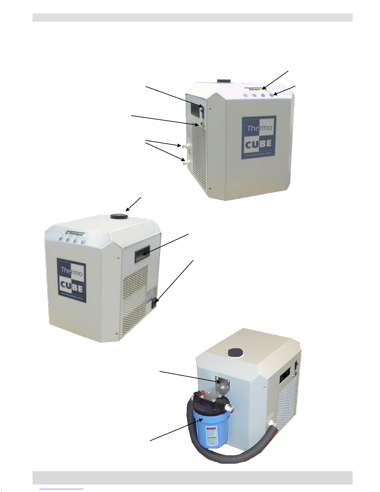
Figure 3A
Figure 3B
Figure 3C
Process Fluid Supply
(¼" push push-in-fittings)
On/Off Switch
Signal Connector
9-Pin D-sub
Fill Cap
Display Screen
Controller Input Buttons
Handle
Power Inlet Module
IEC 320 power inlet module with two 5X20
fuses
Optional 5-micron particle filter
Fasten the filter-mounting bracket
via the four screws located here

THERMOCUBE 200/300/400 THERMOELECTRIC CHILLER MANUAL 52-11300-1
SOLID STATE COOLING SYSTEMS,167 MYERS CORNERS ROAD,WAPPINGERS FALLS,NY 12590 8
TELEPHONE:(845) 296-1300 FAX:(845) 296-1303 WEB:WWW.SSCOOLING.COM VERSION M28
3.1ELECTRICAL CONNECTIONS (SEE FIGURE 3)
Power: The ThermoCube 200/300/400 AC power inlet is an
IEC320-C14 socket. Plug the line cord provided into this socket and
then into the appropriate 115 - 230 VAC 50/60 Hz wall outlet.
Continuous current draw is rated at 7 amps at 115 VAC or 5 amps at
230VAC (50/60 Hz). To ensure safe operation of the unit, it is
important to ensure that the outlet is properly grounded.
A wide variety of power cords are available to support universal
power operation:
Country / Region
Part Number
USA/Canada
22-22333-1
Europe
22-22333-2
Japan
22-22333-3
UK
22-22333-4
Israel
22-22800-1
Australia
22-23213-1
Korean
22-23526-1
China (3 prong)
22-23661-1
NEMA 6-15 208 US Straight
16-23918-1
NEMA L6-15 208 US Twist
16-23918-2
Brazil
22-25122-1
India/South Africa 6A (Type D)
22-26025-1
India/South Africa 15A (Type M)
22-26025-2
Fuses: 10 amp (5mm x 20mm) GDB quick acting glass, meets
IEC 127-2
Replacement Fuse: SSCS#20-22332-10, Allied Electronics
#70149445.
Optional Alarms: Alarm signals are TTL signals, normally high (>4
VDC), located on the 9-pin d-subminiature connector as follows:
System Alarm: Pin 7
Alarm Signal Return: Pin 8
Temperature Alarm: Pin 9
Optional RS-232: The ThermoCube 200/300/400 has an RS-232
communication link option. Connections are made via a 9-pin dsub
connector (see section 7 for wiring and communications details).
3.2PLUMBING CONNECTIONS (SEE FIGURE 3)
The standard process fluid inlet (coolant return) and outlet (coolant
supply) connections, located on the left side, are 1/4” John Guest
“push in” style fittings. See figure 4 for directions on using John
Guest fittings. Other fitting options are available (see section 7).
Important Note: The ThermoCube chiller should be located at
approximately the same level or above the system it is cooling to
avoid coolant draining back into the tank and overflowing after the
ThermoCube is turned off.
WARNING
Electrical Shock
Hazard: Never Plug
in a Line Cord with
Wet Hands

THERMOCUBE 200/300/400 THERMOELECTRIC CHILLER MANUAL 52-11300-1
SOLID STATE COOLING SYSTEMS,167 MYERS CORNERS ROAD,WAPPINGERS FALLS,NY 12590 9
TELEPHONE:(845) 296-1300 FAX:(845) 296-1303 WEB:WWW.SSCOOLING.COM VERSION M28
Figure 4: Using John Guest Fittings

THERMOCUBE 200/300/400 THERMOELECTRIC CHILLER MANUAL 52-11300-1
SOLID STATE COOLING SYSTEMS,167 MYERS CORNERS ROAD,WAPPINGERS FALLS,NY 12590 10
TELEPHONE:(845) 296-1300 FAX:(845) 296-1303 WEB:WWW.SSCOOLING.COM VERSION M28
3.3 AIR CONSIDERATIONS The air inlet and outlet are located on the left and right sides
respectively. Restricting airflow into or out of the unit will impair
performance. At least 3 inches of clearance is required on each side
to ensure adequate airflow.
An optional Air Filter is also available (see Section 7 for options).
3.4COOLANT FILL The coolant fill cap is located at the top rear of the unit. Twist off
the cap counter-clockwise to open. Fill reservoir prior to starting
unit. Close cap before operating
Recommended Coolants:
Solid State Cooling Systems recommends using Koolance, a pre-
mixed 27% propylene glycol/water based coolant containing an
algaecide and corrosion inhibitors. Though it comes in several
colors, SSCS recommends the colorless or blue versions in 700 ml
bottles, part number: LIQ-702CL-B (clear) or LIQ-702B-B (blue),
as the dyes in the other colored versions can form small particulates
when not well mixed.
Contact Koolance for details:
Koolance USA
2840 West Valley Highway North
Auburn, WA 98001
(253) 893-7551
Water or ethylene glycol/water mixtures are also acceptable as
coolants.
Note that algae growth can occur when water is used without at
least 25% propylene or ethylene glycol.
WARNING
Read the Coolant MSDS
Prior to filling the chiller
Use only recommended
coolants
CAUTION

THERMOCUBE 200/300/400 THERMOELECTRIC CHILLER MANUAL 52-11300-1
SOLID STATE COOLING SYSTEMS,167 MYERS CORNERS ROAD,WAPPINGERS FALLS,NY 12590 11
TELEPHONE:(845) 296-1300 FAX:(845) 296-1303 WEB:WWW.SSCOOLING.COM VERSION M28
SECTION 4
START UP ______________________________________________________
Note: In order to avoid injury or damage, operators must only use this product in the
manner specified below.
Start-up the ThermoCube 200/300/400 using the following steps:
1) Connect coolant tubing to fluid connections located on the left
side of the unit, labeled Process Out (supply) and Process In
(return).
2) Connect Alarm Signal connector (if option chosen).
3) Remove the reservoir cap on top and fill the reservoir to just
below the bottom of its neck with coolant. Replace cap.
4) Plug line cord into 115 - 230 VAC, 50/60 Hz.
5) Turn on switch located on the left side of the unit. The front
display should read the current coolant temperature. If the front
display reads “TANK LEVEL LOW”, add more coolant to the
reservoir until the display changes to read the coolant
temperature.
Important Notes:
1) If the tank level low alarm persists, or if another alarm is
displayed, consult section 6.0 of this manual.
2) If using an alcohol/water mixture, do not exceed 25% alcohol or
the reservoir level float may not rise sufficiently when filled to
turn off the tank level low alarm.
SECTION 5
OPERATION _____________________________________________________
The ThermoCube 200/300/400 is operated via the control panel
located on the front panel. The control panel has a 16-character
LCD display and four input keys: UP, DOWN, ENTER, and
START/STOP. These keys work as follows:
Key
Action
UP
Pressing the UP key raises the parameter value displayed.
DOWN
Pressing the DOWN key lowers the parameter value displayed
ENTER
Pressing the ENTER key momentarily enters the parameter changed.
ENTER
Pressing and holding the ENTER key for 3 seconds causes the chiller to change the
display menu (see menu structure)
START/STOP
Pressing the START/STOP key turns on temperature control.
START/STOP
Pressing the START/STOP key while the chiller is operating turns off temperature
control (Operating Mode = *).
WARNING
Electrical Shock
Hazard: Never Plug
in a Line Cord with
Wet Hands
Running the
ThermoCube dry
(no fluid) may
damage the pump
CAUTION

THERMOCUBE 200/300/400 THERMOELECTRIC CHILLER MANUAL 52-11300-1
SOLID STATE COOLING SYSTEMS,167 MYERS CORNERS ROAD,WAPPINGERS FALLS,NY 12590 12
TELEPHONE:(845) 296-1300 FAX:(845) 296-1303 WEB:WWW.SSCOOLING.COM VERSION M28
5.1 SIMPLE OPERATION The ThermoCube 200/300/400 comes with preset operating
parameters that will work well for most applications. If temperature
control at one temperature is desired, follow the steps below.
1) Turn on the ThermoCube and wait for display to read TEMP.
2) Press the UP or DOWN keys to change SETTEMP1 to the
desired set point.
3) Press ENTER to accept the value.
4) Press the START/STOP key to begin controlling to the
temperature just entered (SETTEMP1). The Operating Mode
will now show “‒” (cooling) or “+” (heating).
5) Pressing START/STOP while the unit is controlling temperature
will stop temperature control. The Operating Mode will now
show “*” for Standby (not controlling).
Caution: Do not externally shut off the flow of coolant for more than
a ten second period; pump damage will result if run deadheaded for
extended periods of time.
The ThermoCube will now control to the set point temperature. To
change the set point temperatures just press the UP or DOWN keys
again to change SETTEMP 1 to the new set point, followed by
ENTER and then START/STOP.The Operating Mode will now
show “‒” (cooling) or “+” (heating). If the Operating Mode shows
“*”, press START/STOP to begin controlling.
5.2 ADVANCED OPERATION The ThermoCube 200/300/400 controller has three menus: the Status
Menu, the Temperature Input Menu and the Parameter Input Menu.
The Status Menu shows the chiller operating status and current
temperature of fluid leaving the chiller (see figure 5). The Status
Menu also allows input of new coolant temperature set-points when
the cycling feature is off. The Temperature Input Menu allows input
of set point temperatures; soak times, number of cycles if cycling
between two temperatures, and an alarm temperature. The Parameter
Input Menu allows input of the temperature units; the time units for
soak times, the PID parameters and the auto tune function.
The PID parameters have been preset at the factory for most
applications. If, however, temperature control in not sufficiently
accurate or if overshoot is excessive, the PID parameters may be
modified. Unless the user is well versed in PID theory, we
recommend calling Solid State Cooling Systems technical support
group for assistance.

THERMOCUBE 200/300/400 THERMOELECTRIC CHILLER MANUAL 52-11300-1
SOLID STATE COOLING SYSTEMS,167 MYERS CORNERS ROAD,WAPPINGERS FALLS,NY 12590 13
TELEPHONE:(845) 296-1300 FAX:(845) 296-1303 WEB:WWW.SSCOOLING.COM VERSION M28
MENU STRUCTURE:
UP = Increase Value
DOWN = Decrease Value
↵Press Enter Momentarily
START/STOP = Alternately Starts or Stops temperature control
Press & Hold Enter Key 3 Sec to move from one menu to another
SIMPLE OPERATION
ADVANCED OPERATION
STATUS MENU
TEMPERATURE INPUT MENU
PARAMETER INPUT MENU
TEMP: XX.X°C (current temp)
SETTEMP1 (set point 1)
TEMPUNIT
P
RESS
UP
OR
DOWN
(change set point)
↵
↵
SETTIME1 (time at set point 1)
TIMEUNIT
SETTEMP1 XX.X°C
↵
↵
↵
SETTEMP2 (set point 2)
AUTOTUNE
P
RESS
START/STOP
(to begin
controlling at SETTEMP1)
↵
↵
SETTIME2 (time at set point2)
P1 HEAT
TEMP: XX.X°C (current temp)
↵
↵
PRESS
START/STOP
(to stop
controlling temperature)
#OF CYCLES (default = 0)
I1 HEAT
↵
↵
ALARM TEMP
D1 HEAT
↵
↵
(return to top of menu)
P2 COOL
↵
I2 COOL
↵
D2 COOL
↵
(return to top of menu)
Press ENTER key once to scroll between menu items (↵).
Press and hold ENTER key for 3 seconds to move between menus ( ).
Pressing and holding ENTER key while in the Parameter Input Menu will return you to the Status Menu.
If the unit includes the AUTO RESTART option, the unit will begin temperature control when it is first
turned on using whatever Set Point was entered when the unit was powered off.
Note: If the user enters the temperature input or the parameter input menu and does not press a key for
10 seconds the display will revert back to the Status menu.

THERMOCUBE 200/300/400 THERMOELECTRIC CHILLER MANUAL 52-11300-1
SOLID STATE COOLING SYSTEMS,167 MYERS CORNERS ROAD,WAPPINGERS FALLS,NY 12590 14
TELEPHONE:(845) 296-1300 FAX:(845) 296-1303 WEB:WWW.SSCOOLING.COM VERSION M28
Status Menu: The status menu displays the chiller operating status
and coolant temperature. The chiller operating mode is shown in the
display’s first character: (See Figure 5)
Figure 5: Operating Display
* = Standby mode, chiller is not controlling temperature
‒ = Cooling mode, chiller is controlling temperature and process
fluid temperature is above the set point
+ = Heating mode, chiller is controlling temperature and process
fluid temperature is below the set point
The process fluid (coolant) outlet temperature is shown after TEMP
in °C or °F.
Pressing the UP or DOWN keys with the # of cycles set to zero
(default) will change the set point temperature upon pressing the
ENTER, then the START/STOP key.
Temperature Input Menu: The temperature input menu allows input
of operating temperatures, soak times, number of cycles desired, and
an optional alarm temperature. Note: If # of cycles is set to zero,
only TEMP 1 and ALARM TEMP will be used.
SETTEMP1 = Set-point of first control temperature.
If # OF CYCLES is set to zero, this is the control temperature.
SETTIME1 = Soak time at temperature 1.
Not used if # OF CYCLES is set to zero.
SETTEMP2= Set-point of second control temperature.
Not used if # OF CYCLES is set to zero.
SETTIME2 = Soak time at temperature 2.
Not used if # OF CYCLES is set to zero.
# OF CYCLES = Number of cycles between temperature 1 and
temperature 2, 0-999 cycles. If set to zero, then the
ThermoCube will continuously control at temperature 1.
ALARMTEMP = Alarm temperature range +/- set-point. The unit
will output an alarm via RS-232 when the coolant temperature
is above set-point + ALARMTEMP or below set-point
‒ ALARMTEMP.
‒ TEMP 20.0 °C
Temperature Units
Process Fluid Temperature
Operating Mode

THERMOCUBE 200/300/400 THERMOELECTRIC CHILLER MANUAL 52-11300-1
SOLID STATE COOLING SYSTEMS,167 MYERS CORNERS ROAD,WAPPINGERS FALLS,NY 12590 15
TELEPHONE:(845) 296-1300 FAX:(845) 296-1303 WEB:WWW.SSCOOLING.COM VERSION M28
Parameter Input Menu: The parameter input menu allows input of
temperature units, time units, PID parameters, and turns on or off
auto-tune.
TEMPUNIT = °C or °F
TIMEUNIT = s: seconds, m: minutes, h: hours
AUTOTUNE = ON/OFF.
ON turns on auto-tune where the controller determines PID
parameters. Once PID parameters have been determined AUTO-
TUNE reads OFF.
P1 HEAT = Proportional band for heating, 0-99.9 °C or °F.
P1 HEAT Factory Default Value = 5.6
I1 HEAT = Integral term for heating, 0-999 seconds
I1 HEAT Factory Default Value = 22
D2 HEAT = Derivative term for heating, 0-999 seconds
D2 HEAT Factory Default Value = 2
P2 COOL = Proportional band for cooling, 0-99.9 °C or °F
P2 COOL Factory Default Value = 2.8
I2 COOL = Integral term for cooling, 0-999 seconds
I2 COOL Factory Default Value = 22
D2 COOL = Derivative term for cooling, 0-999 seconds
D2 COOL Factory Default Value = 2
5.3 ALARMS The ThermoCube chiller has two TTL level alarms, one for
temperature and one for system failure:
Temperature: TTL high (>4 VDC) fluid temp below alarm set point
TTL low (<0.5 VDC) fluid temp above alarm set point
System: TTL high (>4 VDC) system operating normally
TTL low (<0.5 VDC) system failure has occurred
A list of system failures causing the system alarm to change to TTL
low can be found in Section 6. In the event of a system failure, the
alarm type will be shown on the front display.
5.4 AUTO-TUNING Some models of the ThermoCube 300 and 400 chillers come with an
automatic tuning (auto-tune) feature. Changing the PID parameters
is normally not recommended unless the RTD probe is moved to a
new location. However, the controller can calculate new PID
parameters via the auto-tune function.

THERMOCUBE 200/300/400 THERMOELECTRIC CHILLER MANUAL 52-11300-1
SOLID STATE COOLING SYSTEMS,167 MYERS CORNERS ROAD,WAPPINGERS FALLS,NY 12590 16
TELEPHONE:(845) 296-1300 FAX:(845) 296-1303 WEB:WWW.SSCOOLING.COM VERSION M28
The following keystrokes initiate the auto-tune function:
1) Press and hold the Enter key until the Status Menu changes to the
Temperature Input menu.
2) Press and hold the Enter key again until the Temperature Input
menu changes to the Parameter Input menu.
3) Press the Enter key three times. The display should read
AUTOTUNE off.
4) Press the Up key to change off to on.
5) Press and hold the Enter key until the parameter input menu
returns to the Status Display.
6) Press the Start key once. The left most display character will
show the letter A until the auto tune is complete. The
ThermoCube will then begin controlling at the set point
temperature.
5.5 MANUAL TUNING For users well versed in PID theory, Solid State Cooling Systems
recommends the closed-loop “Ziegler Nichols” method for manually
tuning the controller. The method consists of three steps:
1) Turn off both the integral and derivative terms for heating and
cooling by setting I1, I2, D1, and D2 to zero.
2) Set proportional band to 50 °C. Begin controlling the process at
the desired set-point temperature. Look for a small-sustained
oscillation in the coolant temperature. Observe the status menu
operating mode character and note if system is heating (+) or
cooling (-). If no oscillation occurs, lower the proportional band
in 50% increments until a small oscillation occurs. Write down
this proportional band setting (P)
3) Measure the “Natural Frequency” (t) of the system in seconds.
This is the time required for the temperature oscillation to cycle
from one maximum temperature to the next maximum
temperature.
Now set the controller input parameters as follows:
P1 HEAT = 2*P if system was heating in step 2.
P1 HEAT = 4*P if system was cooling in step 2.
I1 HEAT = 1.2*t
D1 HEAT = t/8
P2 COOL = P if system was heating in step 2.
P2 COOL = 2*P if system was cooling in step 2.
I2 COOL = 1.2*t
D2 COOL = t/8
THERMOCUBE 200/300/400 THERMOELECTRIC CHILLER MANUAL 52-11300-1
SOLID STATE COOLING SYSTEMS,167 MYERS CORNERS ROAD,WAPPINGERS FALLS,NY 12590 17
TELEPHONE:(845) 296-1300 FAX:(845) 296-1303 WEB:WWW.SSCOOLING.COM VERSION M28
5.6DRAIN PROCEDURE
1. Attach a hose the “Process Out” port of the chiller and place the
end of it in a container with at least a 3 liter capacity.
2. Turn the unit on (making sure to hold the drain hose in place)
and run it until air starts to shoot out of the hose.
3. Attach the drain hose to the “Process In” port of the chiller
4. Remove the tank cap and allow the liquid in the chiller’s lines to
drain out.
5. Replace and tighten the tank cap, then remove the drain hose.
6. Dispose of the coolant in a manner consistent with local
regulations.
SECTION 6
SYSTEM ALARMS/TROUBLESHOOTING ________________________________
The ThermoCube 200/300/400 has multiple system alarms that
when triggered will show on the display. When an alarm is
displayed the system will not attempt to heat or cool the coolant.
Alarms:
Tank Level Low: Liquid reservoir level is too low. Unless filling for
the first time, check all outside plumbing lines for leaks. Once all
leaks are sealed, remove the cap and add more coolant until the
alarm disappears.
RTD Open: The temperature sensor has failed or its connector has
come loose. Turn off the chiller and disconnect the AC power cord.
Contact SSCS for a replacement RTD, or for a RMA number to
return the unit for RTD replacement.
Fan Fail: Fan is supplying insufficient air to cool the thermoelectric
heat exchanger. Either the fan has failed or the airflow into or out
of the system is blocked. Check that the side air inlet and outlet
gratings are not blocked. The ThermoCube requires at least 3
inches of clearance around these gratings. If airflow is not blocked,
contact SSCS for a replacement fan, or for a RMA number to return
the unit for fan replacement.
Pump Fail: The liquid heat exchanger plate temperature is either too
hot or too cold, indicating pump failure, a blockage in the external
plumbing lines or operation outside the normal 5°C to 50°C coolant
temperature (without –LT or –HT options). Turn off the
ThermoCube and disconnect the AC power cord. Verify that no
kinks or blockages exist in plumbing line, both outside and inside
the ThermoCube. If no coolant flow blockages exist, contact SSCS
for a replacement pump, or for a RMA number to return the unit for
pump replacement.
WARNING
Read the Coolant MSDS
prior to draining the
chiller
Electrical Shock Hazard:
Always unplug the unit
before removing the cover.
WARNING
Do not attempt to service or
repair the unit beyond the
troubleshooting checks
described in this section
without first contacting
Solid State Cooling Systems
WARNING

THERMOCUBE 200/300/400 THERMOELECTRIC CHILLER MANUAL 52-11300-1
SOLID STATE COOLING SYSTEMS,167 MYERS CORNERS ROAD,WAPPINGERS FALLS,NY 12590 18
TELEPHONE:(845) 296-1300 FAX:(845) 296-1303 WEB:WWW.SSCOOLING.COM VERSION M28
No Display:If the liquid crystal display does not illuminate upon
turning on the ThermoCube, the internal 12 or 24VDC power
supply has failed, the diaphragm pump has failed, or the LCD
display has failed. Contact SSCS for a RMA number to return the
unit for replacement of the power supply, diaphragm pump, or
display.
Temperature Control Poor: If no other alarms are present, poor
temperature control indicates the heat load is too great for the chiller,
the TE cooling/heating engine is not receiving power, the PID
constants have been corrupted or the chiller needs repair. First check
the PID constant values shown section 5.2 match the factory
defaults. If not, change the values to the default values. Otherwise,
contact SSCS for technical support.
Important: The tank level low alarm will automatically reset when
the tank is filled. The RTD, Fan and Pump failure alarms will not
reset until the system power is turned off.
THERMOCUBE 200/300/400 THERMOELECTRIC CHILLER MANUAL 52-11300-1
SOLID STATE COOLING SYSTEMS,167 MYERS CORNERS ROAD,WAPPINGERS FALLS,NY 12590 19
TELEPHONE:(845) 296-1300 FAX:(845) 296-1303 WEB:WWW.SSCOOLING.COM VERSION M28
SECTION 7
THERMOCUBE OPTIONS____________________________________________
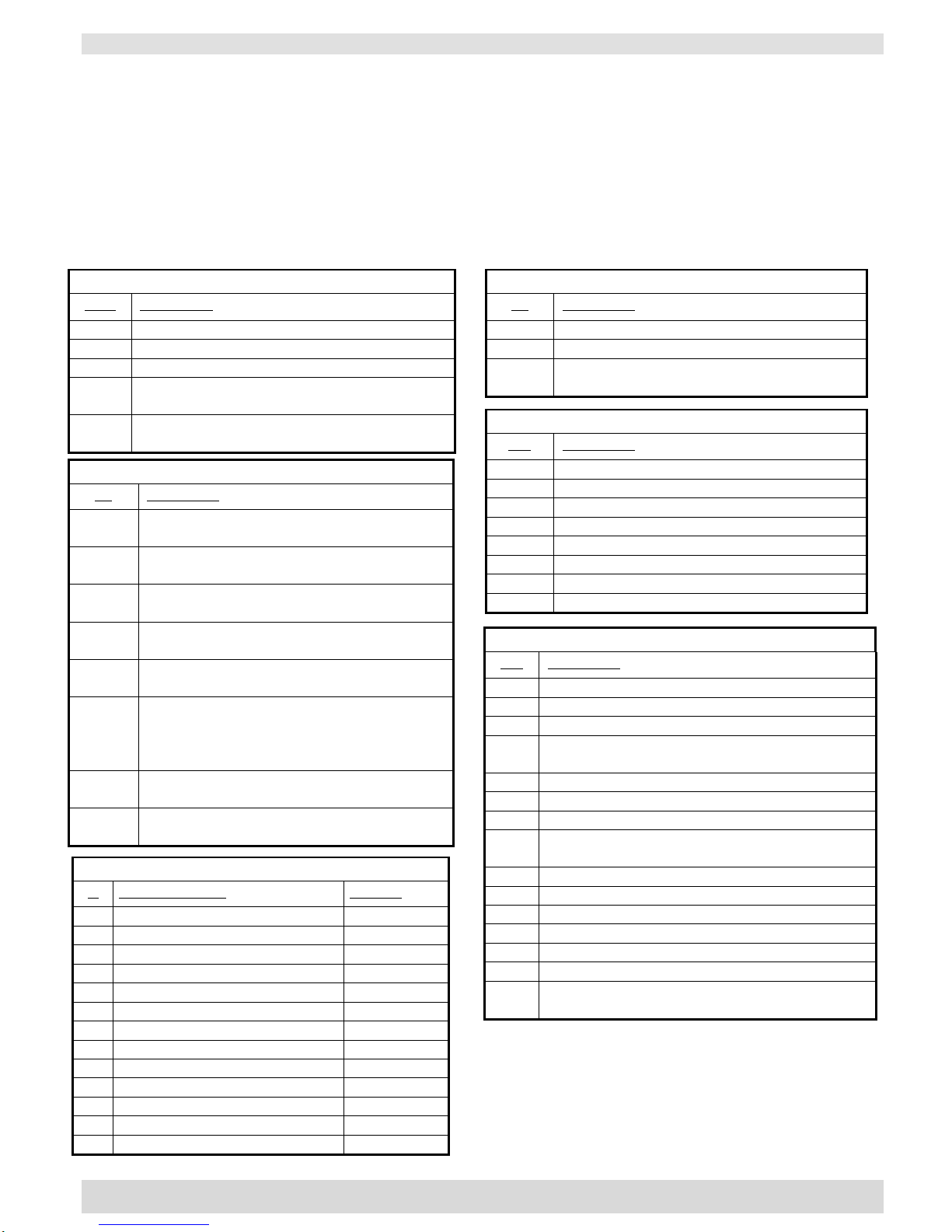
7.1THERMOCUBE OPTIONS AND PART NUMBER
ThermoCube P/N: 10 –CCC –PP –FF –X –YY –OO
Cooling Pump Fan Power Fittings Other
Capacity Type Type Cord Options
CCC = Cooling Capacity (choose one):
CCC
Description
200
200 W @ 20°C in 20°C ambient air
300
300 W @ 20°C in 20°C ambient air
400
400 W @ 20°C in 20°C ambient air
300A
300 W inert gas temperature control
(No pump, No tank, Includes -LT
400AC
400 Watts air conditioner from 20°C house
chilled water. (No pump, No tank)
PP = Pump Type (choose one):
PP
Description
-1D
>1 lpm @ 35 psig diaphragm
(1 year warranty)
-2D
>1.5 lpm @ 35 psig diaphragm
(1 yearr warranty)
-3D
>3 lpm @ 30 psig diaphragm pump
(1 year warranty) , Requires 3/8” fittings
-1G
>1 lpm @ 35 psig magnetic drive gear, low
vibration with stainless steel head
-2G
>2 lpm @ 35 psig magnetic drive gear, low
vibration
-3GXX
>3 lpm @ 30 psig magnetic drive gear, low
vibration (XX = adjusted flow rate: XX=20 for
2 lpm, XX=10 for 1 lpm, XX=15 for 1.5 lpm
etc.) or XX=RF for 3 lpm with run / fill
-1C
~1 lpm @ 17 psig, ~2 liter/min @ 15 psig
centrifugal
-1CL
~1 lpm @ 12 psig, ~2 liter/min @ 10 psig
centrifugal
YY = Inlet/Outlet Fitting Options:
YY
Description
Std
John Guest 1/4” x 1/4” Bulkhead
-J2
John Guest 3/8 x 3/8” Bulkhead
-CP
1/4” CPC shut off valve coolant
-CP2
3/8” CPC shut off valve coolant
-CPM
1/4” CPC metal
-SW
1/4” Swagelok kit
-S2
3/8” Swagelok kit
-FN
1/4” Female NPT Bulkhead
OO = Other Options:
OO
Description
-R2
RS232 interface controller, improved
-EF
5 micron external liquid filter
-AF
External air intake filter
-SS
Stainless steel tank and stainless steel plumbing
(Only available with gear pump)
-ST
Stainless steel tank
-PT
Preset control temperature: (Input temp:___ °C)
-LT
Low temperature (<5°C) operation)
-HT
High temperature up to 65 °C
(60°C max for Centrifugal pumps)
-DC
Dry contact alarm signals
-VD
Vibration dampening material added
-AR
Auto restart – software
-DI
DI water compatible
-FL
Set up for Fluorinert or Galden
-PA
Set up for PAO
-###
Custom engineered special (CES), sequential
number assigned by Engineering
X = Power Cord (select one)
X
Country / Region
Part No.
-1
USA/Canada
22-22333-1
-2
Europe
22-22332-2
-3
Japan
22-22333-3
-4
UK
22-22333-4
-5
Israel
22-22800-1
-6
Australia
22-23213-1
-7
Korean
22-23526-1
-8
China (3 prong)
22-23661-1
-9
NEMA 6-15 208 US Straight
16-23918-1
-10
NEMA L6-15 208 US Twist
16-23918-2
-11
Brazil
22-25122-1
-12
India/South Africa 6A (Type D)
22-26025-1
-13
India/South Africa 15A (Type M)
22-26025-2
FF = Fan Type (choose one):
FF
Description
Blank
Standard fan noise <63 dBA @ 1m
-QF
Quiet Fan (no longer available)
-VS
Variable speed fan, noise
49 dBA to 63 dBA @ 1m
This manual suits for next models
2
Table of contents
Other Solid State Cooling Systems Chiller manuals


Popular Chiller manuals by other brands


oxford diffraction
oxford diffraction KMW150CCD user manual

MTA
MTA TAEevo015 Maintenance and operating manual

Midea
Midea MC-SU30-RN1L Owners & installation manual

Carrier
Carrier PACKAGED AIR COOLED FLOTRONIC 30GB060 Advance product data

Carrier
Carrier 30GT 015 installation instructions

Carrier
Carrier AQUAFORCE 30XW150-400 Operation & service manual