Randell BC-918RI User manual

OPERATOR MANUAL
IMPORTANT INFORMATION, KEEP FOR OPERATOR
PART NUMBER PP MNL2104, REV. A (02/22)
This manual provides information for:
BLAST CHILLERS
BC-918RI, BC-510WT, BC-003UC
THIS MANUAL MUST BE RETAINED FOR FUTURE REFERENCE. READ,
UNDERSTAND AND FOLLOW THE INSTRUCTIONS AND WARNINGS
CONTAINED IN THIS MANUAL.
FOR YOUR SAFETY Do not store or use gasoline or other flammable vapors
and liquids in the vicinity of this or any other appliance.
NOTIFY CARRIER OF DAMAGE AT ONCE It is the responsibility of the
consignee to inspect the container upon receipt of same and to determine
the possibility of any damage, including concealed damage. Unified
Brands suggests that if you are suspicious of damage to make a notation
on the delivery receipt. It will be the responsibility of the consignee to file
a claim with the carrier. We recommend that you do so at once.
Manufacture Service/Questions 888-994-7636.
RETAIN THIS MANUAL FOR FUTURE REFERENCE
NOTICE: Due to a continuous program of product improvement, Unified Brands
reserves the right to make changes in design and specifications without prior notice.
NOTICE: Please read the entire manual carefully before installation. If certain
recommended procedures are not followed, warranty claims will be denied.
MODELNUMBER_________________________
SERIAL NUMBER _________________________
INSTALLATION DATE ______________________
The serial number is located on the interior rear wall
of the Blast Chiller.
EQUIPMENT DESCRIPTION
888-994-7636, fax 888-864-7636
unifiedbrands.net
Information contained in this document is known to be current and accurate at the time of printing/creation. Unified
Brands recommends referencing our product line websites, unifiedbrands.net, for the most updated product information and
specifications. © 2022 Unified Brands. All Rights Reserved.
Model No. Body Style Length Depth Height Pan Capacity
(12” x 20” x
2.5”)
Pan Capacity
(18” x 26”)
NEMA BTU
Requirements
for Remote
Installations
HP Approx.
Weight
BC-003UC Undercounter 27” 30” 35” 3 - 5-20P 5400 @ 20F
Evap Temp 1/2 320
BC-510WT Worktop 59" 34” 36” 10 55-20P 6050 @20F
Evap Temp 3/4 565
BC-918RI Upright 40” 38.7” 71" 18 9L14-20P 12100 @ 20F
Evap Temp 1-1/2 858
BC-918RIBC-510WTBC-003UC

2 OM-BLAST CHILLER
INSTALLATION
SELECTING A LOCATION FOR YOUR NEW UNIT
The following conditions should be considered when selecting a location for
your unit:
1. Floor Load: The area on which the unit will rest must be level, free of vibration,
and suitably strong enough to support the combined weights of the unit plus
the maximum product load weight. All casters or legs must be in contact with
the floor to support the weight. Legs have adjustable feet that can be raised
or lowered. Casters may require shims in order for the caster to be in contact
with the floor. NOTE: If there is a question pertaining to weight load limits,
consult the factory at 1-888-994-7636.
2. Ventilation: The air-cooled self-contained unit requires a sufficient amount
of cool clean air. Avoid surrounding your blast chiller around other heat
generating equipment and out of direct sunlight. Also, avoid locating in
an unheated room or where the room temperature may drop below 55° F
(13°C) or above 86°F (32°C).
3. Clearance: There must be a combined total of at least 3” clearance on all
sides of the unit.
INSTALLATION CHECKLIST
After the final location has been determined, refer to the following checklist prior
to start-up:
1. Check all exposed refrigeration lines to ensure that they are not kinked,
dented, or rubbing together.
2. Check that the condenser and evaporator fans rotate freely without striking
any stationary members.
3. Turn on control once unit has been plugged in or properly wired direct (see
page 15)
4. Allow unit time to cool down to holding temperature. (See page 10 for Unit
Operation).
5. Refer to the front of this manual for serial number location. Please record
this information in your manual on page 3 now. It will be necessary when
ordering replacement parts or requesting warranty service.
6. Confirm that the unit is holding temperature.
7. Allow your unit to operate for approximately 30 minutes before putting in
food to allow interior of unit to cool down to storage temperature.
NOTE: All motors are oiled and sealed.
NOTE:FAILURE TO FOLLOW INSTALLATION GUIDELINESAND RECOMMENDATIONS
MAY VOID THE WARRANTY ON YOUR UNIT.
ELECTRICAL SUPPLY
The wiring should be done by a qualified electrician in accordance with local
electrical codes. A properly wired and grounded outlet will assure proper
operation. Please consult the data tag attached to the compressor to ascertain
the correct electrical requirements. Supply voltage and amperage requirements
are located on the serial number tag located on the rear interior wall.
NOTE: It is important that a voltage reading be made at the compressor
motor electrical connections, while the unit is in operation to verify the correct
voltage required by the compressor is being supplied. Low or high voltage can
detrimentally affect operation and thereby void its warranty.
NOTE: It is important that your unit has its own dedicated line. Condensing
units are designed to operate with a voltage fluctuation of plus or minus 10% of
the voltage indicated on the unit data tag. Burn out of a condensing unit due to
exceeding voltage limits will void the warranty.
OPERATION
The Randell BC series blast chillers are designed for rapid chilling through the
danger zone down to 40°F or below in approximately 90 minutes. The exact chill
time will vary depending on product type. The door must be in closed position to
activate switch at top of door before any cooling cycle will begin.
INTRODUCTION
1. The control software for the BC Control Unit is based on a Real-Time Operating
System and is capable of simultaneously running a chiller operation while at
the same time accepting/displaying user information from the control panel
such as chiller preset adjustments. This document provides an overview of the
current controller features.
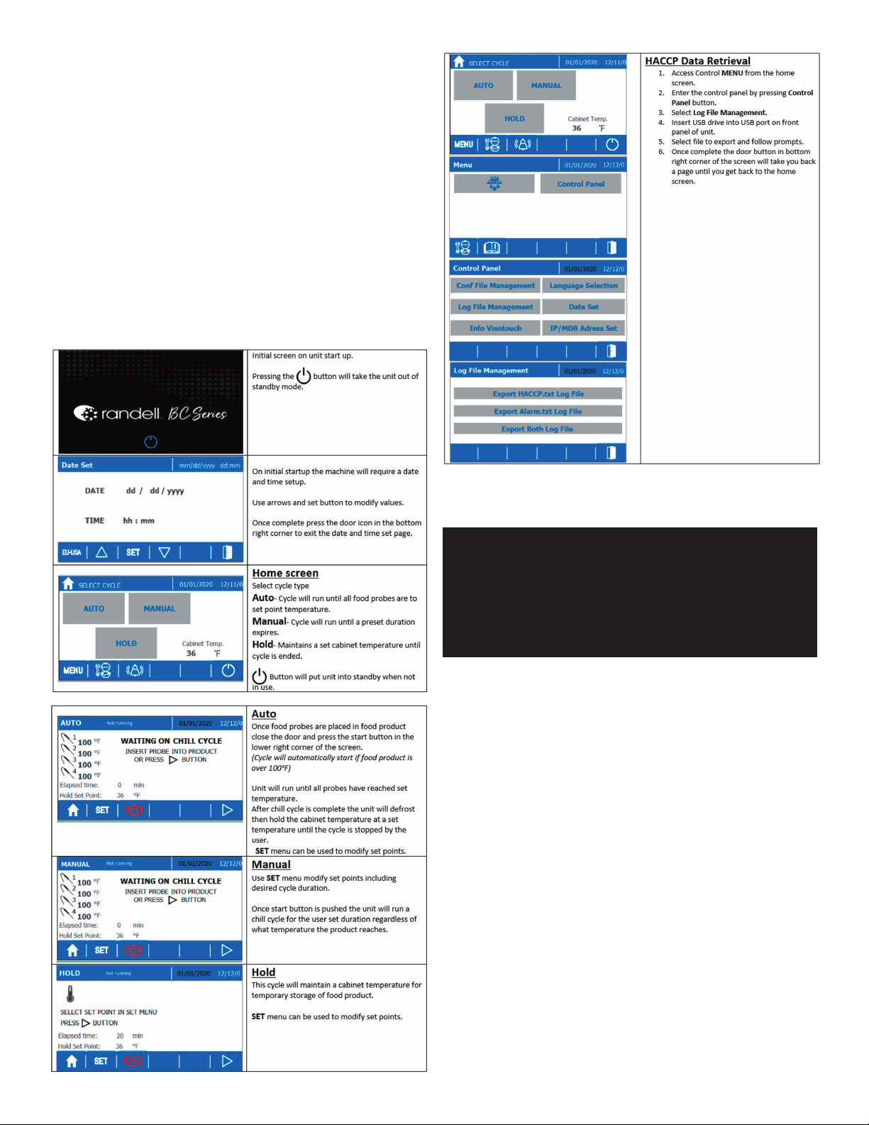
POWERING UP UNIT
1. Once the unit is connected to AC power the touch screen will display a loading
screen with a progress bar.
2. Once loaded the standby screen will be displayed. Depressing the power key
on initial power up will cause the unit to request setting of the date and time.
Adjust the date and time values by touching the desired value, press the set
button then use arrow buttons to adjust value up or down. After all values have
been set press the return button on the bottom right of the screen to return to
the standby screen.
SETTING THE DATE/TIME
1. Upon turning on the unit for the first time, the controller will prompt the user to
set the current date and time of day.
2. To adjust the date or time after initial power up you must access the Date Set
function. This function can be accessed by entering the menu screen from the
home screen then the control panel.
Menu àControl Panel àDate Set
POWERING DOWN UNIT
The unit may be returned to the low power standby state by depressing the
power button. The display will then return to the standby screen. NOTE: Power
should only be removed from the unit while it is idle on this standby screen.
MODES OF OPERATION
The controller can run one of three possible modes, Auto, Manual, or Hold.
1. Auto Mode - Auto Mode will run a chill cycle until all food probes have reached
a preset set point.
a. Auto can be manually selected by pressing the “AUTO” button on the
home screen.
- The food probe set point can be modified by entering the setting menu
via the “SET” button at the bottom of the auto cycle screen.
b. Auto cycle will start automatically from home screen or while running a
hold cycle if food probes are placed directly into food product and probes
have exceeded 100°F
c. Once an auto cycle has completed the unit will perform a defrost cycle.The
word defrost will display on the cycle screen once the defrost cycle has
activated and will remain until the evaporator coil has properly defrosted.
d. After completion of the defrost cycle the unit will hold the cabinet at the
hold set point until the user removes the product and ends the chill cycle
by pressing the “X” in the lower right-hand corner of the cycle screen.
2. Manual Mode - Manual Mode will run a chill cycle for a user set duration that
is not controlled by food probe temperature. Chill cycle will only end when set
duration has expired or user intervention occurs.
3. Hold Mode - Cabinet temperature will be held at a user defined set point.
This can be used to pre chill the cabinet prior to an auto/manual chill cycle or
temporarily hold food product. Not intended for extended food product storage.

3 OM-BLAST CHILLER
USB FLASH DRIVE
Data stored from previous blast chiller cycles and alarms can be retrieved from the
controller’s internal memory and sent to a USB flash drive.This makes for a convenient
method to transfer blast chiller data to a personal computer. Data is written into a file
on the flash drive in a comma delimited form that is suitable for text and spreadsheet
applications. A data transfer to a USB drive is initiated as follows:
1. Access Control MENU from the home screen.
2. Enter the control panel by pressing Control Panel button.
3. Select Log File Management.
4. Insert USB drive into USB port on front panel of unit.
5. Select file to export and follow prompts.
6. Once complete the door button in bottom right corner of the screen will take
you back a page until you get back to the home screen.
QUICK START GUIDE
MAINTENANCE
WARNING: DO NOT USE SHARP UTENSILS AND/OR OBJECTS.
WARNING: DO NOT USE STEEL PADS, WIRE BRUSHES, SCRAPERS, OR CHLORIDE
CLEANERS TO CLEAN YOUR STAINLESS STEEL.
CAUTION: DO NOT USE ABRASIVE CLEANING SOLVENTS, AND NEVER USE
HYDROCHLORIC ACID (MURIATIC ACID) ON STAINLESS STEEL.
WARNING: DO NOT PRESSURE WASH EQUIPMENT AS DAMAGE TO ELECTRICAL
COMPONENTS MAY RESULT.
Unified Brands strongly suggests a preventive maintenance program which would
include the following monthly procedures:
NOTE: When cleaning the interior cabinet place unit into standby mode to prevent
door alarm from becoming active.
MONTHLY PM PROCEDURES
1. Cleaning of all condenser coils. Condenser coils are a critical component in
the life of the compressor and must remain clean to assure proper air flow and
heat transfer. Failure to maintain this heat transfer will affect unit performance
and eventually destroy the compressor. Clean the condenser coils with coil
cleaner and/or a vacuum, cleaner and brush. NOTE: Brush coil in direction of
fins, normally vertically as to not damage or restrict air from passing through
condenser.
2. Clean fan blade on the condensing unit.
3. Clean and disinfect drains with a solution of warm water and mild detergent.
4. Clean and disinfect drain lines and evaporator pan with a solution of warm
water and mild detergent.
5. Clean all gaskets on a weekly if not daily basis with a solution of warm water
and a mild detergent to extend gasket life.

4 OM-BLAST CHILLER
RECOMMENDED CLEANERS FOR YOUR STAINLESS STEEL INCLUDE THE
FOLLOWING:
JOB CLEANING AGENT COMMENTS
Routine cleaning Soap, ammonia,
detergent Medallion
Apply with a sponge or
cloth
Fingerprints and smears Arcal 20, Lac-O-Nu,
Ecoshine Provides a barrier film
Stubborn stains and
discoloration
Cameo, Talc, Zud,
First Impression
Rub in the direction of
the polish lines
Greasy and fatty acids, blood,
burnt-on foods
Easy-Off, Degrease It,
Oven Aid
Excellent removal on all
finishes
Grease and Oil Any good commercial
detergent
Apply with a sponge or
cloth
Restoration/Preservation Benefit, Super Sheen Good idea monthly
Reference: Nickel Development Institute, Diversey Lever, Savin, Ecolab, NAFEM
Proper maintenance of equipment is the ultimate necessity in preventing costly
repairs. By evaluating each unit on a regular schedule, you can often catch
and repair minor problems before they completely disable the unit and become
burdensome on your entire operation.
For more information on preventive maintenance, consult your local service
company or CFESA member. Most repair companies offer this service at very
reasonable rates to allow you the time you need to run your business along with
the peace of mind that all your equipment will last throughout its expected life.
These services often offer guarantees as well as the flexibility in scheduling or
maintenance for your convenience. For a complete listing of current Unified Brands
ASA please visit www.unifiedbrands.net.
Unified Brands believes strongly in the products it manufactures and backs those
products with one of the best warranties in the industry. We believe with the
proper maintenance and use, you will realize a profitable return on your investment
and years of satisfied service.
REPLACEMENT PARTS
To order parts, contact your Authorized Service Agent. Supply the model
designation, serial number, part description, part number, quantity, and when
applicable, voltage and phase.
CONTACT US
If you have questions pertaining to the content in this manual, contact Unified
Brands at 888-994-7636.
ALARMS
ALARM
CODE
DESCRIPTION POSSIBLE CAUSE
RPF Room probe failure Open cabinet air temperature probe circuit.
Caused by faulty probe, broken wire, or bad
connection.
EPF Evaporator probe
failure
Open evaporator temperature probe circuit.
Caused by faulty probe, broken wire, or bad
connection.
NPF Needle probe failure Open needle probe circuit. Caused by faulty
probe, faulty receptacle, broken wire, or bad
connection.
RHT Cabinet
temperature too
high
Refrigeration system not cooling.
Faulty/inaccurate cabinet air temperature probe.
RLT Cabinet
temperature too low
Control relay stuck closed.
Faulty/inaccurate cabinet air temperature probe.
PWF Power failure during
cycle
Unit unintentionally unplugged during use.
CTE Maximum cycle
time expired
Running multiple batches on single cycle.
Faulty needle probe preventing cycle from ending.
DOOR Door alarm Door open for extended amount of time. Ensure
unit is in standby if door is intentionally left open
for extended amounts of time during cleaning.
ACF General
configuration error
Corrupted software
Contact Randell Tech Services
TROUBLESHOOTING
This unit is designed to operate smoothly and efficiently if properly maintained.
However, the following is a list of checks to make in the event of a problem. Wir-
ing diagrams are found at the end of this manual. When in doubt, turn unit off
and contact service at 888-994-7636 or tsrandell@unifiedbrands.net.
SYMPTOM POSSIBLE CAUSE PROCEDURE
Unit doesn’t pre-chill 1. No power to unit
2. Unit in standby mode
3. Dirty Condenser Coil
4. Refrigeration system
fault
1. Check power source
2. Check power switch
3. Clean condenser coil
4. Call ASA for service
AUTO mode ends
but product is not
at temp
1. Probe location
2. Probe faulty
1. Relocate probe to center
mass of product
2. Test probes in ice bath to
see if displayed value is
within +/- 2°F
3. Call ASA for service
AUTO mode ends
and product is frozen
1. Probe location
2. Probe faulty
1. Relocate probe to center
mass of product
2. Test probes in ice bath to
see if displayed value is
within +/- 2°F
3. Replace probe
Freezing product
or product not cold
enough
1. Probe location
2. Improper set point
3. Faulty cabinet air
probe.
1. Clean probes
2. Test probes in ice bath to
see if displayed value is
within +/- 2°F
3. Check probe receptacle for
any damage
4. Validate set point value
Moisture around
drawer or frame
1. Gasket not sealing
2. Gasket torn
1. Adjust gasket
2. Replace gasket
Ice in drain pan or
water in bottom of
unit or floor
1. Drain tube clogged
2. Unit not level
1. Clean drain
2. Adjust leveling leg/shim
casters

5 OM-BLAST CHILLER
WARRANTY
Congratulations on the purchase of your new Unified Brands equipment. We hope you
enjoy many years of reliable service in connection with the same. Please review all of
the important safety and operational information contained in the Operator’s Manual
for this equipment before it is placed in service. If you have any questions related to
equipment set up, operations, or service, please call 888-994-7636.
In addition, please review the sales terms and conditions set forth below.
*****IMPORTANT NOTICE*****
WARRANTIES, LIMITATIONS ON WARRANTIES, AND LIMITATION OF REMEDIES
The following Warranties, Limitation on Warranties, and Limitation of Remedies are
included in the terms of sale for this product. Please read this entire warranty and all
warranty modifications, disclaimers, and limitations of remedies set forth herein before
accepting or using this equipment or product. Customer acknowledges and accepts
the provisions of this notice by Customer’s acceptance and use of the product. If these
provisions are not acceptable and agreed to by Customer, then please return this
product in its unused condition to Unified Brands or a Unified Brands authorized dealer.
UNIFIED BRANDS warrants this product against defects in material and workmanship
under normal use and services for which this product was designed. This warranty
runs only to the original end user and is in lieu of any other liability for defects.
THE WARRANTIES EXPRESSED IN THESE TERMS AND CONDITIONS ARE IN PLACE
OF ANY AND ALL OTHER EXPRESS WARRANTIES (UNLESS SEPARATELY STATED IN
PRINTED MATERIAL PREPARED BY US DESCRIBING OUR EQUIPMENT) AND EXCLUDE
ALL IMPLIED WARRANTIES, INCLUDING, BUT NOT LIMITED TO, ANY WARRANTY OF
MERCHANTABILITY OR FITNESS FOR ANY PARTICULAR PURPOSE; NOR ARE THERE
ANY OTHER WARRANTIES, EXPRESS OR IMPLIED, BY OPERATION OF LAW OR
OTHERWISE. In no event shall UNIFIED BRANDS be liable for damages or delay or
for any consequential, special or contingent damages arising out of any breach of
our warranty, whether or not we have knowledge of specific needs or our employees
or agents have given any specific assurances. Anyone claiming that there has been
a breach of warranty by UNIFIED BRANDS must give us written notice within THIRTY
(30) days after discovery of the relevant defect or the right to assert such claim will
have been waived conclusively and provided further that any such claim must also be
asserted within the general warranty period for such equipment and/or parts.
UNIFIED BRANDS will not be liable for any expense incurred without our prior written
authorization for alterations made outside of our factory or for repairs which are
not performed by UNIFIED BRANDS authorized service departments using UNIFIED
BRANDS factory parts. Nor shall we be responsible for the performance of equipment
as to which any repairs, revisions or alterations have been made by others.
THE EXCLUSIVE REMEDY OF THE USER OR BUYER AND THE EXCLUSIVE LIABILITY OF
UNIFIED BRANDS OR ANY SELLER OF UNIFIED BRANDS PRODUCTS, FOR ANY AND ALL
CLAIMS, LOSSES, INJURIES, OR DAMAGES (INCLUDING CLAIMS BASED ON BREACH
OF WARRANTY, CONTRACT, NEGLIGENCE, TORT, STRICT LIABILITY, OR OTHERWISE)
RESULTING FROM OR ARISING OUT OF THE USE OF HANDLING OF THIS PRODUCT,
SHALL BE THE RETURN OF THE PURCHASE PRICE OR AN AMOUNT NOT TO EXCEED
THE ORIGINAL PURCHASE PRICE OF THE PRODUCT OR, AT THE ELECTION OF UNIFIED
BRANDS OR THE SELLER, THE REPLACEMENT OF THE PRODUCT.
https://unifiedbrands.net/
Randell-Warranty-Information

6 OM-BLAST CHILLER
Parts List
BC-918RI
UNIT ASSM/CONTROL PANEL
CALL FACTORY FOR REPLACEMENT PARTS:
888-994-7636
BC-918RI
BC-510WT
BC-003UC
ITEM PART NUMBER DESCRIPTION
1 RF CNT1707 CONTROL, XB887D X X X
2 RF CNT1708 CONTROL, TOUCHSCREEN XXX
3 EL CNT1901 USB CONNECTOR X X X
4 EL CNT1902 USB CONNECTOR CAP X X X
5 PP STK1902 LABEL, FRONT PANEL CONTROL SURROUND X X
6 RP PNL2102 CONTROL PANEL, BC-918, LEFT HAND X
7 EL SWT9901 SWITCH, BLAST CHILLER DOOR X X
8EL TRN0304 TRANSFORMER, 120V:24V 40VA 599 CLASS II X X X
9 RF CAP1101 CAPACITOR, 14MFD 440VAC, PN-450-20-0148 X
10 RF CAP1201 BOOT, NEOPRENE RUBBER FOR RF CAP1101 X
11 HD CST200 CASTER, 5.5" OA, W/O BRAKE X X X
12 HD CST201 CASTER, 5.5" OA, WITH BRAKE X X X
13 RP LVR1401 LOUVER, BC-918RI X
14 EL BEP1901 BUZZER, PUI AUDIBLE X
NS RF CNT1709 CONTROL, CONNECTOR KIT X X X
NS EL WIR1901 USB CABLE, CONTROL TO USB CONNECTOR X X X
NS HD LEG9902 LEG, PRE-ASSEMBLED - OPTIONAL X X X
NS RP PNL2103 CONTROL PANEL, BC-918, RIGHT HAND X
NS HD RCK0601SS UNIVERSAL PAN SLIDE, S/S X X
NS = NOT SHOWN
13
12
11

7 OM-BLAST CHILLER
Parts List
BC-918RI
DOOR ASSEMBLY
CALL FACTORY FOR REPLACEMENT PARTS:
888-994-7636
BC-918RI
BC-510WT
BC-003UC
ITEM PART NUMBER DESCRIPTION
20 RP DOR1402 REFRIGERATED DOOR ASSEMBLY, LEFT HINGE X
21 RP PRB1101 FOOD PROBE HOLDER X X X
22 IN GSK9904 GASKET, 24.25 X 41.41 BC 20 NC10492 X
23 RP HIN0001 HINGE, ADJUSTABLE REACH IN X
24 HD HDL1101 HANDLE, HEAVY DUTY TUBULAR, SATIN FINISH X
NS EL WIR0222 WIRE, FOOD PROBE EXT X X X
NS EL WIR0223 WIRE, DOOR SWITCH EXT X X X
NS HD PRB0202 FOOD PROBE, WHITE XXX
NS HD PRB1903 FOOD PROBE, RED X
NS HD PRB1904 FOOD PROBE, GREEN X X
NS HD PRB1905 FOOD PROBE, BLACK X
NS RP DOR1401 REFRIGERATED DOOR ASSEMBLY, RIGHT HINGE X
NS = NOT SHOWN

8 OM-BLAST CHILLER
Parts List
BC-918RI
CONDENSING UNIT
CALL FACTORY FOR REPLACEMENT PARTS:
888-994-7636
BC-918RI
BC-510WT
BC-003UC
ITEM PART NUMBER DESCRIPTION
30 RF CON151S COND UNIT, 1.5HP 230V X
31 EL WIR274-220 CONDENSATE HEATER ELEMENT X
32 RF FLT376 FILTER DRYER, 3/8" X
33 RF COI003 COIL, SOLENOID DANFOSS 120V X X
34 RF VLV005 VALVE, LIQUID LINE SOLENOID X X
NS EL WIR0226 WIRE, AC POWER INPUT CABLE X
NS EL BRK9906 BREAKER, 2 POLE 20 AMP X
NS EL WIR470-14 POWER CORD, 14GA 2' MALE X
NS = NOT SHOWN

9 OM-BLAST CHILLER
Parts List
BC-918RI
EVAPORATOR COIL ASSEMBLY
CALL FACTORY FOR REPLACEMENT PARTS:
888-994-7636
BC-918RI
BC-510WT
BC-003UC
ITEM PART NUMBER DESCRIPTION
40 RF FAN1902 FAN, AXIAL, 315mm DIA, 120V, WITH CORD X
41 RF COI1803 COIL, 19x20 BLAST CHILLER X X
42 RP PIL1401 PILASTER, RACK BRACE, SET OF THREE, HINGED LEFT X
43 RP PIL1402 PILASTER, RACK BRACE, SET OF THREE, HINGED RIGHT X
44 RF VLV1102 VALVE, EXPANSION X X
NS = NOT SHOWN

10 OM-BLAST CHILLER
Parts List
BC-510WT
MAIN ASSM/REF. DOOR/CONTROL PANEL
CALL FACTORY FOR REPLACEMENT PARTS:
888-994-7636
BC-918RI
BC-510WT
BC-003UC
ITEM PART NUMBER DESCRIPTION
50 RP LVR1701 LOUVER, BC-510WT X
51 RP HNG1701 HINGE, DOOR TOP, 38MM WIDE X
52 RP HNG025 HINGE, SPRING LOAD ASSY, SELF-CLOSING X
53 RP DOR1602L DOOR, LH BC-510WT X
54 RP DOR1602R DOOR, RH BC-510WT X
NS IN GSK1025 GASKET, 21.57 X 24.25 PUSH IN X
55 RP PNL2104 CONTROL PANEL, BC-510WT LEFT HAND X
55A RP PNL2105 CONTROL PANEL, BC-510WT RIGHT HAND X
NS = NOT SHOWN

11 OM-BLAST CHILLER
Parts List
BC-510WT
EVAP. COIL/CONDENSING UNIT
CALL FACTORY FOR REPLACEMENT PARTS:
888-994-7636
BC-918RI
BC-510WT
BC-003UC
ITEM PART NUMBER DESCRIPTION
60 RF FAN1401 FAN, AXIAL, 119 x 38mm X
61 RF FAN0703 FAN GUARD, NICKEL CHROME FINISH WIRE X
62 RP PIL1701 PILASTER, RACK BRACE, SET OF THREE, HINGED LEFT X
63 RP PIL1702 PILASTER, RACK BRACE, SET OF THREE, HINGED RIGHT X
70 RF CON1801 COND UNIT, 3/4HP LT R404 120V X
71 RF FLT377 FILTER, 1/4" X
NS EL SWT0502 SWITCH, ROCKER 20A,277V,1HP,125V X
NS = NOT SHOWN
44
62
61
60
41
63
70
71
44
33 34

12 OM-BLAST CHILLER
Parts List
BC-003UC
MAIN ASSM/DOOR ASSM
CALL FACTORY FOR REPLACEMENT PARTS:
888-994-7636
BC-918RI
BC-510WT
BC-003UC
ITEM PART NUMBER DESCRIPTION
80 HD CST2030 CASTER, 3-7/8" O/A SWVL NO BRAKE X
81 RP DOR1707 DOOR, BC3, W/SWITCH, LH X
82 RP HNG9900 DOOR HINGE X
NS IN GSK1020 GASKET, 15.59 X 24.25 PUSH IN X
83 RP PNL2106 CONTROL PANEL, BC-003UC X
84 RP LVR2102 LOUVER, BC-003UC X
NS = NOT SHOWN
90
91
92
93
80
81
82
84
83
95
96 97
8
1
2
9 10
90
91
92
93
80
81
82
84
83
95
96 97
8
1
2
9 10

13 OM-BLAST CHILLER
Parts List
BC-003UC
MECHANICAL
CALL FACTORY FOR REPLACEMENT PARTS:
888-994-7636
BC-918RI
BC-510WT
BC-003UC
ITEM PART NUMBER DESCRIPTION
90 RF CON2001 EMERSON COND UNIT, 1/2 MED R404A 120V/60/1 X
91 EL WIR274 CONDENSATE HEATER ELEMENT X
92 RF CNT700 CONTROL, SINGLE LOW PRESSURE X X
93 RF SOL9801 SOLENOID, VALVE & 120V COIL X X
NS RF FLT251 DRYER, 1/4"FILTER W/2ND 1/4 X
NS EL WIR456 WIRE, 18" DRAIN EVAP FEMALE X X
NS EL WIR461-12 20A POWER CORD, 9' 12GA X X
95 RF COI9904 COIL, 12x17-1/4 BLAST CHILLER X
96 EL MTR9902 MOTOR, FAN, 120V, 60HZ X
97 RF BLD9905 BLADE, 12" EVAPORATOR FAN X
NS RF VLV9801 VALVE, 1 TON R404 HI-TEMP X
NS = NOT SHOWN

14 OM-BLAST CHILLER
Wiring Diagram
BC-918RI
CALL FACTORY FOR REPLACEMENT PARTS:
888-994-7636
Atmel
VALV EDIG INP BDIG INP AAn OUTProbe B Probe A
PwrSupply 24VLD1
12 56789101112131415161718
45 46 47 48 49 50
39 40 41 42 43 44
34 35 36 37 3830 31 32 3326 27 28 2921 22 23 24 25
LD2
LD3
LD4
LD5
2345 678
LD6
LD7
LD8
60 61 64 65 66 67
62 63
SEE A-A Hookups
AIR PROBE (HD PRB0201)[50]
COIL PROBE (HD PRB0201) [49]
BLK
BLK
BLK
GRN/YEL
BLU
BWN
RF FAN1101
EL WIR274-220
REFG SOLENOID
RF VLV005
RF COI003
JUNCTION BOX
BLK
BLK
RF CAP1101
BLK
GRN/YEL
BLU
BWN
RF FAN1101
EL WIR274-220
RIB BLK
BLK
BLK
RIB BLK
RED 18ga
BLUBLU
RF CAP1101
BLK 18ga
BLU 18ga
WHT 18ga
GRN 18ga
BLK 18ga
BLU 18ga
WHT 18ga
GRN 18ga
BLK 12ga
GRN 12ga
RED 12ga
RED 16ga
BLK 16ga
RED 16ga
BLK 16ga
BLK 18ga
WHT 18ga
FOOD PROBES
YEL 16ga
DOOR SWITCH
USB
USB
(EL SWT9901)
BLK 16ga
WHT 16ga
YEL 16ga
BLK 16ga
WHT 16ga
WHT 16ga
RF CNT1707
RF CNT1708
RED 16ga
BLK 16ga
YEL 16ga
BLK 16ga
END CAP EL CNT1303
BLOCK EL CNT1301
(1-REQUIRED)
(4-REQUIRED)
BLK 16ga
GRN 16ga
PRB 1
(42)
PRB 2
(43)
PRB 3
(45)
PRB 4
(48)
PRB 1 - HD PRB0202 (WHITE)
PRB 2 - HD PRB1904 (GREEN)
PRB 3 - HD PRB1905 (BLACK)
PRB 4 - HD PRB1903 (RED)
V4
V2
V3
V1
+12V
DI 6
DI 5
DI 4
Com
DI 3
DI 2
DI 1
Com
AO 3
Com
AO 2
Com
AO 1
gnd
PB7
PB6
+12V
+5V
Com
PB5
PB4
Com
PB3
PB2
PB1
Vnr
gnd
NO
NO
NO
NO
Com
Com
Com
Com
NO
NO
NO
NO
C
NC
Ser
Port
- +
R5485
- +
Rem
Dsp
+ -
A-A Hookups
6-15R
RED
BLK
CONTACTOR
BLK
COIL
SR CON151S
6-15P
BW
1-1/2 HP COMP
208/230v-60hz-1ph LOW PRESS
CONTROL
BW
Pwr
Ext
-
+
VNR
Supp
EL CNT1902
EL CNT1901
EL TRN0304
120v/24v
AC Trans
40VA
BUZZER
10-24 NUT
10-24X1"
GND STUD
BLK
LINE
LOAD
EL PLG8411
9' CORD (12ga)
14-20P
CONTROL PANEL
BLK 12 ga
RED 12ga
GRN 12ga
WHT 12ga
NOTE
ABOUT GROUNDING
CONTROL BOARD:
NO CONNECTION
TO CHASSIS
GROUND
EL BRK9906
20A DBL
POLE BRKR
EL WIR375
BLK 18ga
BLU 18ga
BLK 18ga
BLU 18ga
BLK 10ga
RED 10ga
BLKREDGRNWHT
GND
BLK

15 OM-BLAST CHILLER
Wiring Diagram
BC-510WT
CALL FACTORY FOR REPLACEMENT PARTS:
888-994-7636
Atmel
VALVED IG INP BD IG INP A An OUT Probe B Probe A
PwrSupply 24V LD1
12 56 78 91 01 11 21 31 41 51 6 17 18
45 46 47 48 49 50
39 40 41 42 43 44
34 35 36 37 3830 31 32 3326 27 28 2921 22 23 24 25
LD2
LD3
LD4
LD5
2345 678
LD6
LD7
LD8
606 16 46 56 6 67
626 3
SEE A-A Hookups
DOOR SWITCH
USB
USB
(EL SWT9901)
WHT 16ga
YEL 16ga
BLK 16ga
WHT 16ga
RF CNT1707
RF CNT1708
RED 16ga
BLK 16ga
YEL 16ga
BLK 16ga
BLK 16ga
YEL 16ga
BLK 16ga
WHT 16ga
GRN 16ga
COND FAN
COMPRESSOR
PSIG
SWITCH
OL
REL CAP
INSTALL 5-20P CORD SET
BLK
BLK
WHT
BLK
WHT
REF SOLENOID
J BOX
CONDENSING UNIT
POWER
SWITCH
BLK
GRN
BLK
WHT
BLK
WHT
RF CNT700
SR CON800-E
BLUB LU
BLK
GRN
WHT
RF SOL9801
EVAPORATOR FANS
BLK
WHT
EL FAN1401
EL WIR466M
EL WIR466F
WHT
GRN
RED
YEL
AIR PROBE (HD PRB0201)[50]
COIL PROBE (HD PRB0201) [49]
FOOD PROBES
PRB 1
(42)
PRB 2
(43)
PRB 3
(45)
PRB 4
(48)
PRB 1 - HD PRB0202 (WHITE)
PRB 2 - HD PRB1904 (GREEN)
PRB 3 - HD PRB1905 (BLACK)
PRB 4 - HD PRB1903 (RED)
(OPTIONAL)
(OPTIONAL)
V4
V2
V3
V1
+12V
DI 6
DI 5
DI 4
Com
DI 3
DI 2
DI 1
Com
AO 3
Com
AO 2
Com
AO 1
gnd
PB7
PB6
+12V
+5V
Com
PB5
PB4
Com
PB3
PB2
PB1
Vnr
gnd
NO
NO
NO
NO
Com
Com
Com
Com
NO
NO
NO
NO
C
NC
Ser
Port
- +
R5485
- +
Rem
Dsp
+ -
A-A Hookups
Pwr
Ext
-
+
VNR
Supp
EL CNT1902
EL CNT1901
EL TRN0304
120v/24v
AC Trans
40VA
MECHANICAL PANEL
BLK
CONTROL PANEL

16 OM-BLAST CHILLER
Wiring Diagram
BC-003UC
CALL FACTORY FOR REPLACEMENT PARTS:
888-994-7636
Atmel
VALVED IG INP BD IG INP AA n OUTP robe B Probe A
PwrSupply 24V LD1
12 56 78 91 01 11 21 31 41 51 6 17 18
45 46 47 48 49 50
39 40 41 42 43 44
34 35 36 37 3830 31 32 3326 27 28 2921 22 23 24 25
LD2
LD3
LD4
LD5
2345 678
LD6
LD7
LD8
606 16 46 56 6 67
626 3
SEE A-A Hookups
(HD PRB0201)[50]
(HD PRB0201) [49]
(HD PRB0202) [48]
USB
USB
WHT 16ga
YEL 16ga
BLK 16ga
WHT 16ga
RF CNT1707
RF CNT1708
ORG 16ga
BLK 16ga
YEL 16ga
BLK 16ga
BLK 16ga
EL WIR461-12
INSTALL 5-20P CORD SET
AIR PROBE
COIL PROBE
FOOD PROBES
END CAP EL CNT1303
BLOCK EL CNT1301
(2-REQUIRED)
(4-REQUIRED)
V4
V2
V3
V1
+12V
DI 6
DI 5
DI 4
Com
DI 3
DI 2
DI 1
Com
AO 3
Com
AO 2
Com
AO 1
gnd
PB7
PB6
+12V
+5V
Com
PB5
PB4
Com
PB3
PB2
PB1
Vnr
gnd
NO
NO
NO
NO
Com
Com
Com
Com
NO
NO
NO
NO
C
NC
Ser
Port
- +
R5485
- +
Rem
Dsp
+ -
A-A Hookups
Pwr
Ext
-
+
VNR
Supp
EL CNT1902
EL CNT1901
EL TRN0304
120v/24v
AC Trans
40VA
POWER
SWITCH
EL SWT145
BLK
GRN
WHT
COND FAN
COMPRESSOR
PSIG
SWITCH
OL
REL CAP
CONDENSING UNIT
SR CON9902
RF CNT700
HEATER 200W
CONDENSATE
EL WIR274
EVAPORATOR FAN
REF SOLENOID
EL MTR9902
RF SOL9801
GND
CONTROL PANEL
BLK
GRN BLK WHT
J BOX

17 OM-BLAST CHILLER
Service Log
Model No: Purchased From:
Serial No: Location:
Date Purchased: Date Installed:
Purchase Order No: For Service Call:
Date Maintenance Performed Performed By
This manual suits for next models
2
Table of contents
Other Randell Chiller manuals
Popular Chiller manuals by other brands

AIREDALE
AIREDALE SmartCool SN Series Technical manual

Nordcap
Nordcap SF 19/15-CW CRIO CHILL manual

Daikin
Daikin EWWD J Series Installation, operation and maintenance manual

York
York Millennium YCAR 0100SC Wiring diagram

Johnson Controls
Johnson Controls YORK YMC2 Wiring diagram

Carrier
Carrier 19FA Series Application data