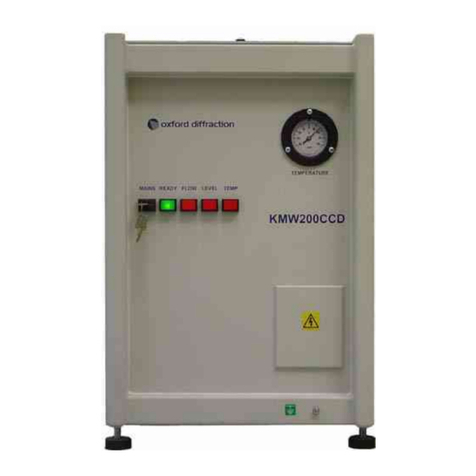
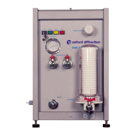
oxford diffraction KMW150CCD User manual

User Manual
KMW150CCD
Water Chiller Unit for the Sapphire series CCD Detector
October 2001
Version 1.1
Oxford Diffraction Limited
20 Nuffield Way, Abingdon, Oxfordshire.
OX14 1RL. UK
Tel: +44 (0)1235 532132
Fax: +44 (0)1235 528005
http://www.oxford-diffraction.com

KMW150CCD Version 1
USER MANUAL KMW150CCD Chiller v1.1.doc Page ii
Important Information
This user manual is intended to help the user operate the KMW150CCD water chiller unit
manufactured in Poland by Oxford Diffraction.
Product: KMW150CCD
Model Type: CCD chiller unit
Electrical Ratings: 1/N AC 230 V
50/60 Hz
150 Watts
Before attempting to operate the system, PLEASE READ THE
INSTRUCTIONS.
This product should only be used by persons legally permitted to do so.
If the equipment is used in a manner not specified in the User Manual, the protection provided by
the equipment may be impaired.
Important Health and Safety Notice
When returning components for service or repair it is essential that the item is shipped together with
a signed declaration that the product has not been exposed to any hazardous contamination or that
appropriate decontamination procedures have been carried out so that the product is safe to
handle.
Care has been taken to ensure the information in this manual is accurate and at an appropriate
level. Please inform Oxford Diffraction if you have any suggestions for corrections of improvements
to this manual.
This users' manual has been written according to standard 89/392/EEC and further modifications.
Xcalibur is a trademark of Oxford Diffraction Limited in some jurisdictions and a registered
trademark of Oxford Diffraction Limited in other jurisdictions.
Oxford Diffraction acknowledges all trademarks and registrations.
Copyright 2000 Oxford Diffraction Limited. All rights reserved. No part of this document may be
reproduced or distributed in any form, or by any means, or stored in a database or retrieval system,
without prior written permission of Oxford Diffraction.

CONTENTS
KMW150CCD Version 1
USER MANUAL KMW150CCD Chiller v1.1.doc Page iii
Contents
1. Health and Safety Information ........................................................1
1.1 General.................................................................................................................................... 1
1.2 Electrical Safety....................................................................................................................... 1
1.2.1 Potential Electrical Hazards ........................................................................................... 2
1.2.2 Recommended Precautions........................................................................................... 2
1.2.3 First Aid .......................................................................................................................... 2
1.3 Mechanical Handling Safety.................................................................................................... 3
1.4 Safe Mechanical Practice........................................................................................................ 3
1.5 Moving Parts ........................................................................................................................... 3
1.6 Modifications and Service ....................................................................................................... 3
2. Introduction ......................................................................................4
2.1 Scope ...................................................................................................................................... 4
2.2 How to Use This Manual ......................................................................................................... 4
2.3 System Description ................................................................................................................. 4
3. Specifications...................................................................................5
3.1 Environment ............................................................................................................................ 5
3.2 Performance Data ................................................................................................................... 5
3.3 Electrical Services ................................................................................................................... 5
3.4 Water Supply........................................................................................................................... 5
4. Technical Description......................................................................6
4.1 Overview ................................................................................................................................. 6
4.2 Operating Principles ................................................................................................................ 7
4.2.1 Water Conditioning Check ............................................................................................. 9
4.3 Interfaces............................................................................................................................... 10
4.3.1 Water Supply................................................................................................................ 10
4.3.2 Electrical Connections.................................................................................................. 11
5. Handling, Installation, Storage and Transit Information ............12
5.1 Reception and Handling........................................................................................................ 12
5.1.1 Delivery ........................................................................................................................ 12
5.1.2 Unpacking .................................................................................................................... 12
5.1.3 Weights, Dimensions and Lifting Points....................................................................... 12
5.2 Installation and Setting to Work ............................................................................................ 13
5.2.1 Preparation of Site and Services ................................................................................. 13
5.2.1.1 Environmental Requirements ............................................................................. 13
5.2.1.2 System Layout .................................................................................................... 13
5.2.1.3 Electrical Services............................................................................................... 13
5.2.1.4 Water Supply ...................................................................................................... 13
5.2.2 Setting to Work............................................................................................................. 13
5.2.2.1 Equipment Required ........................................................................................... 14
5.2.2.2 Setting up Procedures ........................................................................................ 14
5.3 Storage.................................................................................................................................. 15
6. Operating Instructions ..................................................................16
6.1 Warnings and Cautions......................................................................................................... 16
6.2 Controls and Indicators ......................................................................................................... 16

CONTENTS
KMW150CCD Version 1
USER MANUAL KMW150CCD Chiller v1.1.doc Page iv
6.3 Switch-on Procedure ............................................................................................................. 16
7. Maintenance Schedule ..................................................................17
7.1 Introduction............................................................................................................................ 17
7.2 Annual Maintenance Schedule ............................................................................................. 17
8. Maintenance Instructions..............................................................18
8.1 Filling the Reservoir with Water ............................................................................................ 18
8.2 Cleaning the Water Filter....................................................................................................... 19
9. Trouble Shooting ...........................................................................20
10. Spares...........................................................................................21
11. Additional Information.................................................................22
11.1 Drawings ............................................................................................................................. 22
12. CE Conformity Notice..................................................................23

HEALTH AND SAFETY INFORMATION
KMW150CCD Version 1
USER MANUAL KMW150CCD Chiller v1.1.doc Page 1
1. Health and Safety Information
1.1 General
In normal operation the system is designed to operate safely. All users of the KMW150CD water
chiller unit should be aware of potential hazards which exist in and around equipment of this type
and the ways of avoiding possible injury and equipment damage which may result from
inappropriate ways of working. A description of such potential hazards and how to avoid them is
given in this section.
This manual adopts the following convention:
WARNING
Indicates a potential hazard which may result in injury or death
CAUTION
Indicates a potential hazard which may result in damage to equipment
Warning symbols on the equipment are:
Protective conductor terminal
Earth (ground) terminal
CAUTION
Risk of electric shock
CAUTION
Refer to accompanying documents
See original manufacturers' manuals for further safety data on third party equipment supplied with
the system. A list of these is given in this manual.
WARNING
Do not take risks. You have a responsibility to ensure the safe
condition and safe operation of equipment.
1.2 Electrical Safety
In normal use the user is protected from the dangers associated with the voltage, current and power
levels used by the equipment. Only suitably qualified personnel should attempt to disconnect,
dismantle or modify the equipment.

HEALTH AND SAFETY INFORMATION
KMW150CCD Version 1
USER MANUAL KMW150CCD Chiller v1.1.doc Page 2
1.2.1 Potential Electrical Hazards
The following list is not intended as a complete guide to all the electrical hazards on the system, but
serves to illustrate the range of potential hazards that exist:
•electric shock
•electric burn
•fire of electrical origin
•electric arcing
1.2.2 Recommended Precautions
WARNING
All of the electrical equipment supplied as part of the system should
be provided with a protective ground. Do not remove protective
grounds as this may give rise to an electrical safety hazard. It is
vitally important that the system is properly grounded at all times.
Follow local and national electrical regulations and procedures.
Do not defeat interlocks, remove connectors, disconnect equipment,
open safety covers, dismantle or modify equipment unless you are
qualified and authorised to do so and you are fully conversant with its
operation and potential hazards or have total assurance through your
local electrical permit to work system that the equipment has been
made safe.
Make sure that the mains supply is fused at an appropriate rating and
that it can be isolated locally via a clearly labelled, clearly visible and
easily accessible isolating switch. Isolate the supply before carrying
out any maintenance work.
1.2.3 First Aid
A course in first aid to include methods of artificial respiration is recommended for those whose
work involves equipment which may produce a high voltage.
WARNING
Do not attempt to administer first aid to someone who may have
suffered electric shock until the source of the shock has been
isolated.
Mains voltages are present in the system. These can cause serious
injury or death.
Only personnel qualified and experienced to work with such currents
and voltages should perform service or maintenance work on this
equipment.

HEALTH AND SAFETY INFORMATION
KMW150CCD Version 1
USER MANUAL KMW150CCD Chiller v1.1.doc Page 3
1.3 Mechanical Handling Safety
WARNING
Lifting points are provided for safe handling of components and safe
handling practice must be observed to comply with local regulations.
Check that lifting points are used only for the job intended.
The system itself and some components are heavy and require
careful handling. Use safe lifting procedures for heavy items to
prevent possible strain injury.
1.4 Safe Mechanical Practice
In normal use personnel are not required to undertake mechanical work. However, servicing or
repair may necessitate access to any part of the system. Only suitably qualified personnel should
attempt to dismantle, modify or repair equipment.
Water connections should be made and tested in accordance with any local and national safety
regulations.
1.5 Moving Parts
There are a number of moving parts in the system which are powered by electric motors.
Warning
Injury could result if clothing or body parts become caught in moving
mechanisms.
Keep clothing, hands etc. away from moving mechanisms.
1.6 Modifications and Service
The manufacturer will not be held responsible for the safety; reliability or performance of the
equipment unless assembly operations, extensions, re-adjustments, modifications and repairs are
carried out only by persons authorised by the manufacturer. It should be stressed that those parts of
the equipment which are interchangeable, and which are subject to deterioration during operation,
may significantly affect the safety of the equipment.

INTRODUCTION
KMW150CCD Version 1
USER MANUAL KMW150CCD Chiller v1.1.doc Page 4
2. Introduction
2.1 Scope
This manual applies to the KMW150CCD water chiller unit designed and manufactured by Oxford
Diffraction.
2.2 How to Use This Manual
This manual is aimed at operators of the KMW150CCD who should be trained laboratory
technicians and should have been trained to use the KMW150CCD by Oxford Diffraction personnel.
This manual is intended to provide operators with a practical guide to the system and its operation.
This is intended to familiarise the operator with how the system works and provide a better
understanding of the system operation.
All personnel who are likely to operate the system or come into contact with any of the system
components should read the SAFETY section of the manual. This provides basic information aimed
at highlighting the safety hazards associated with the equipment.
The purpose of this manual is to:
•explain how to operate the equipment
•explain how to interface to the equipment
•list performance characteristics of the equipment
•describe how the equipment operates
•assist with simple fault finding and maintenance
2.3 System Description
The KMW150CCD is a stand-alone chiller unit intended for indoor use. It is designed for use with
the Sapphire seriers CCD detector.
The chiller has the following purposes:
To stabilise the temperature of the cooling water that is supplied to the CCD detector
To electronically control the flow of water to the CCD detector.
To control the supply of power to the CCD detector

SPECIFICATIONS
KMW150CCD Version 1
USER MANUAL KMW150CCD Chiller v1.1.doc Page 5
3. Specifications
3.1 Environment
Ambient temperature 10°C to 35°C
Storage temperature 10°C to 40°C
Relative humidity 10 – 95% non – condensing
Location Inside a building
3.2 Performance Data
Water flow 1.0 l/min
Water temperature 12-14 ºC
Temperature stability ±2 ºC
Water reservoir capacity 25 l
3.3 Electrical Services
Power connection 1/N AC 230V, 50/60 Hz
Maximum power consumption 150 W
Maximum mains current 1.0 A
CCD output power consumption 150 W
Main fuse T2.5 A
3.4 Water Supply
Reservoir water Optically clear, neutral pH, de-ionised water
Connections Quick-release type, designed for pipes of size 10 x 3 mm

TECHNICAL DESCRIPTION
KMW150CCD Version 1
USER MANUAL KMW150CCD Chiller v1.1.doc Page 6
4. Technical Description
4.1 Overview
Figure 4.1.1 Front View of KMW150CCD Water Chiller
The KMW150CCD Chiller consists of a metal cabinet containing a water reservoir, a compressor
with a radiator, and control circuitry.
Controls and indicators are located on the front panel of the chiller. Water and electrical connections
are located on the side of the chiller. An overflow pipe from the water reservoir is located on the
back of the chiller.
Overflow
i
Outlet
Inlet
Manual
valves -
filters
Power
connectors
Mains
CCD output

TECHNICAL DESCRIPTION
KMW150CCD Version 1
USER MANUAL KMW150CCD Chiller v1.1.doc Page 7
Figure 4.1.2 Side and Back Views of the KMW150CCD Water Chiller
4.2 Operating Principles
Inside the KMW150CCD, the compressor is connected to a radiator that is immersed in the water
reservoir. A thermostat connected to the compressor ensures that the temperature of the water in
the reservoir stays in the range 12-14 ºC (or higher depending on the dew point of the operating
environment), as required by the CCD detector.
The control circuitry of the KMW150CCD has a logic unit. The logic unit checks signals from:
1. Temperature and water level sensors inside the water reservoir
2. A flow sensor
3. The water pump
4. The compressor.
Refer to Figure 4.2.1 for a schematic diagram of the control circuit.

TECHNICAL DESCRIPTION
KMW150CCD Version 1
USER MANUAL KMW150CCD Chiller v1.1.doc Page 8
Figure 4.2.1 Schematic Diagram of the Control Circuit

TECHNICAL DESCRIPTION
KMW150CCD Version 1
USER MANUAL KMW150CCD Chiller v1.1.doc Page 9
4.2.1 Water Conditioning Check
The KMW150CCD performs a water conditioning check when it is initially switched on. This check
looks at:
1. The flow rate of the water
2. The level of the water in the reservoir
3. The temperature of the water in the water reservoir.
The pump stops after 10 seconds if either the rate of water flow, or the water level in the reservoir,
is too low.
The pump stops after 10 minutes if the water temperature in the water reservoir exceeds 18ºC.
The state of the unit is displayed on four status lights on the front panel.
Figure 4.2.2 Water Conditioning Check Routine of the KMW150CCD
READY Lamp ON
CCD output ON
Key switch ON
Pump ON
Flow
Level
Temperature
READY Lamp OFF
CCD output OFF
Sensor’s subroutine
TRUE
FALSE
LOOP FOR EVER
Wait 10 sec
PUMP OFF

TECHNICAL DESCRIPTION
KMW150CCD Version 1
USER MANUAL KMW150CCD Chiller v1.1.doc Page 10
Figure 4.2.3 Sensor’s Subroutine Flow Chart
4.3 Interfaces
4.3.1 Water Supply
Two water connections are located on the left side panel of the KMW150CCD. The connectors are
combined with manual valves and filters. The connectors are screw type and are designed for pipes
of size 10 x 3 mm.
Flow
Level
Temp
Wait 10 sec Wait 10 min
Flow
Level
Temp

TECHNICAL DESCRIPTION
KMW150CCD Version 1
USER MANUAL KMW150CCD Chiller v1.1.doc Page 11
4.3.2 Electrical Connections
CON1
1 MAINS socket A J1-1
2 MAINS socket B J1-2
3 Key switch A J2-1
4 Key switch B J2-2
5 Pump and compressor powering A J3-1
6 Pump and compressor powering B J3-2
7 CCD socket A J4-1
8 CCD socket B J4-2
CON2
16 Temperature sensor A J5-3
15 Temperature sensor B J5-2
14 Flow sensor GND J5-1
13 Flow sensor SIGNAL J6-3
12 Level sensor A J6-2
11 Level sensor B J6-1
10 Not connected
9 Not connected
8 Flow sensor +5V J7-1
7 Lamp common J8-3
6 Not connected
5 Not connected
4 LEVEL status light J9-2
3 TEMP status light J9-1
2 FLOW status light J8-2
1 READY status light J8-1

HANDLING, INSTALLATION, STORAGE AND TRANSIT INFORMATION
KMW150CCD Version 1
USER MANUAL KMW150CCD Chiller v1.1.doc Page 12
5. Handling, Installation, Storage and
Transit Information
5.1 Reception and Handling
5.1.1 Delivery
The following steps should be carried out on delivery of the system and before unpacking the
KMW150CCD chiller.
1. When the system arrives, check that there is no visible damage, with the delivery driver present.
If damage has occurred contact the carrier and Oxford Diffraction immediately.
2. Check that shock-watch and tilt indicators fitted to the outside of the packing case have not
been activated. If the indicators have been activated notify Oxford Diffraction immediately.
3. Check the number of delivered items against the packing list. If any items are missing contact
Oxford Diffraction within 3 days.
WARNING
The packing crate is heavy and could cause serious injury and
damage to the equipment if not handled correctly. Use suitable lifting
equipment and procedures. Only lift the packing case from the
bottom.
CAUTION
Do not remove the equipment from the packing crate until it has been moved to its
designated installation site. The equipment has been carefully packed to protect the
equipment from damage in transit. Removal of the packing equipment could make
the equipment vulnerable to damage during transit.
4. Always lift the packing case from the bottom using suitable lifting equipment (refer to list of
component weights in the following section.
5. Move the packing case into the designated installation site.
5.1.2 Unpacking
1. Retain all packing material until installation of the system is completed.
5.1.3 Weights, Dimensions and Lifting Points
Description Weight
kg
Dimensions
(width x height x depth)
cm
Centre of
gravity
Lifting points
KMW150CCD Chiller 20 45 x 53 x 52 Centre of
unit
Underneath at the
four corners

HANDLING, INSTALLATION, STORAGE AND TRANSIT INFORMATION
KMW150CCD Version 1
USER MANUAL KMW150CCD Chiller v1.1.doc Page 13
5.2 Installation and Setting to Work
5.2.1 Preparation of Site and Services
5.2.1.1 Environmental Requirements
It is the customer’s responsibility to ensure that all local building and safety regulations are met.
Ensure that the environmental conditions of the installation site conform to the requirements stated
in the SPECIFICATIONS section of this manual.
5.2.1.2 System Layout
The minimum distance between the back, or side of the casing, and other equipment must be
greater than 30 cm.
Do not place the KMW150CCD close to any other heat-producing equipment.
5.2.1.3 Electrical Services
The electrical supply must conform to the requirements stated in the SPECIFICATIONS section of
this manual.
Locate the electricity supply close to the system and provide:
Phase L
Neutral N
Protection PE
The mains plug should be readily reachable by the operator when the equipment has been
installed.
5.2.1.4 Water Supply
Prepare 25 litres of clean distilled water to fill the reservoir.
5.2.2 Setting to Work
The location of connectors on the KMW150CCD is shown in figure 5.2.1.

HANDLING, INSTALLATION, STORAGE AND TRANSIT INFORMATION
KMW150CCD Version 1
USER MANUAL KMW150CCD Chiller v1.1.doc Page 14
Figure 5.2.1 Electrical and Water Connections on the Side of the KMW150CCD
5.2.2.1 Equipment Required
25 litres of distilled water
Bucket
Funnel
Power cable for Sapphire series CCD camera
Mains power cable for KMW150CCD
Water pipes (x2, thickness 10 x 3 mm)
5.2.2.2 Setting up Procedures
1. Connect the water pipes between the CCD camera and the KMW150CCD. Refer to figure 5.2.2
NOTE: Water can flow through the Sapphire series CCD camera in either direction.
Pi p e s 10 /3 mm
Figure 5.2.2 Water pipe connection between KMW150CCD and the Sapphire series CCD
detector
Mains IN
CCD
Output
Outlet valve
Inlet valve and
filter
Quick release
fittings

HANDLING, INSTALLATION, STORAGE AND TRANSIT INFORMATION
KMW150CCD Version 1
USER MANUAL KMW150CCD Chiller v1.1.doc Page 15
2. Remove the top cover of the KMW150CCD.
3. Place a bucket under the overflow pipe at the rear of the KMW150CCD.
WARNING
Do not allow water to splash on the electrical circuits of the
KMW150CCD. Failure to do this could cause an electrical shock
hazard, and possible damage to the equipment.
4. Using the funnel, fill the reservoir with water, until water starts to come out of the overflow pipe.
5. Refit the cover on the KMW150CCD.
6. Open the manual valves on the side of the KMW150CCD.
CAUTION
When inserting the Sapphire series CCD detector cable into the KMW150CCD,
ensure that the connectors are pushed home firmly.
7. Connect the power cable for the Sapphire series CCD camera between connector on the CCD
camera and the socket marked as CCD on the KMW150CCD. Refer to figure 5.2.3.
Figure 5.2.3 Electrical power supply to the KMW150CCD
8. Plug the KMW150CCD power cable into the socket marked Mains IN on the KMW150CCD.
9. Plug the other end of the KMW150CCD power cable into the mains electrical supply.
10. The KMW150CCD is now ready to use.
5.3 Storage
Before installation commences, or when the system is not being used for extended periods, store
the KMW150CCD in accordance with the environmental conditions for temperature and humidity
stated in the SPECIFICATIONS section of this manual.
Always store the KMW150CCD chiller in a secure room.
Mains
supply
KMW150CCD
CCD detector’s power
supply unit
Mains IN CCD

OPERATING INSTRUCTIONS
KMW150CCD Version 1
USER MANUAL KMW150CCD Chiller v1.1.doc Page 16
6. Operating Instructions
6.1 Warnings and Cautions
WARNINGS
Dangerous voltages are present on the KMW150CCD’s terminals
when the power is turned on. To prevent personal injury and possible
damage to the equipment:
1. Never connect/disconnect the Sapphire series CCD detector cable
from the KMW150CCD when the unit is turned on.
2. Turn off the unit at the mains and remove the plug before filling up
the reservoir with water as live parts and rotating parts are
exposed when the cover is removed.
3. Ensure that the earth cable is properly connected to the
KMW150CCD casing.
6.2 Controls and Indicators
The controls and indicators of the KMW150CCD are located on the front panel.
The KMW150CCD is switched on/off using the mains key switch.
There are four indicator lights marked ‘Ready’, ‘Flow’, ‘Level’ and ‘Temp’. The four lights flash when
the chiller is performing its automatic water conditioning check. When the chiller is operating
correctly the green light illuminates and the three red lights go out.
A temperature gauge indicates the temperature of the water in the reservoir.
6.3 Switch-on Procedure
1. Check that the water pipes and electrical cables are properly connected.
2. Switch on the KMW150CCD by turning the key switch to the right.
The lights on the front panel will flash as the KMW150CCD performs a water conditioning
check.
3. After a few seconds, check that the green light on the front panel is illuminated.
This shows that there is no fault and that the CCD power is on. If the green light does not come
on, refer to the TROUBLE SHOOTING chapter.
4. The KMW150CCD is now operational.
Table of contents
Other oxford diffraction Chiller manuals
Popular Chiller manuals by other brands

York
York YCIV0177S/P manual

SMC Networks
SMC Networks HRL100-A Operation manual

Cornelius
Cornelius 75' Service manual

Cleveland
Cleveland Horizontal Tumble Chiller P-TC-120 Specification sheet

York
York YCAL0043E Series Installation operation & maintenance

Carrier
Carrier Flotronic 30GB Wiring, controls and troubleshooting

York
York YCIV Series Installation operation & maintenance

AERMEC
AERMEC NRB 0800 Installation and maintenance manual

Lindab
Lindab Plafond Service maintenance manual

Cornelius
Cornelius ENERGIZE 6 installation manual

Weber
Weber Refrigerator owner's guide

SMC Networks
SMC Networks HRLE Series Operation manual