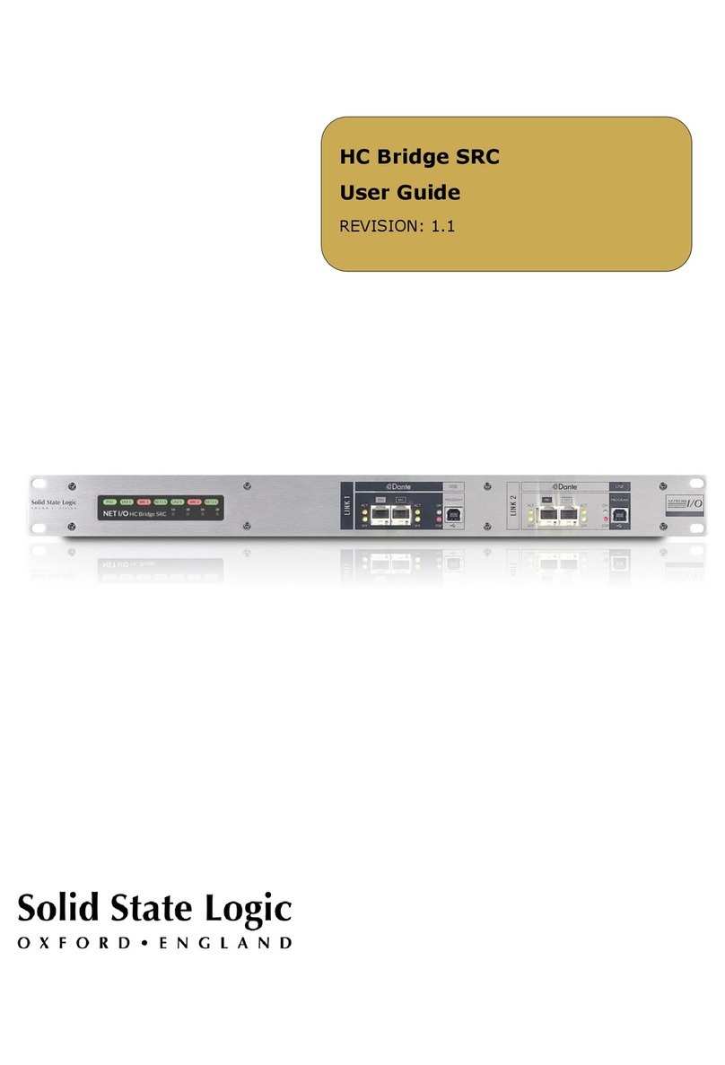
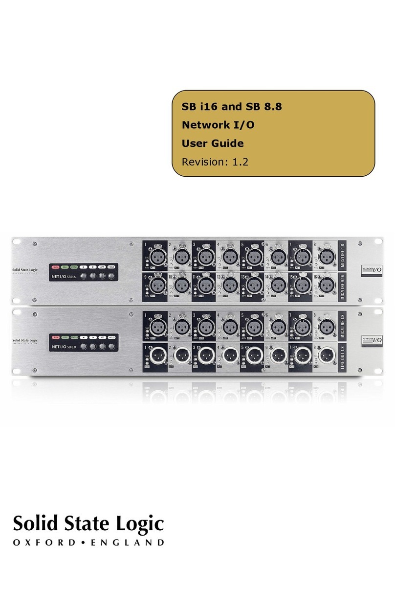
Solid State Logic SB 32.24 User manual

SB 32.24 and SB 16.12
Network I/O
User Guide
Revision: 1.5

SB 32.24 and SB 16.12 User Guide
2
Visit SSL®at
www.solidstatelogic.com
© Solid State Logic
All rights reserved under International and Pan-American Copyright Conventions
SSL and Solid State Logic are ® registered trademarks of Solid State Logic.
SSL®, Solid State Logic®, Total Recall®and Tempest®
are ® registered trademarks of Solid State Logic.
SuperAnalogue™, System T™, Live L100™, Live L200™, Live L300™, Live L350™, Live L500™,
Live L500 Plus™, Live L550™, Blacklight™ and X-Light are ™ trademarks of Solid State Logic.
Dante™ and Audinate™ are trademarks of Audinate Pty Ltd.
etherCON®is a registered trademark of Neutrik AG.
All other product names and trademarks are the property of their respective owners
and are hereby acknowledged.
No part of this publication may be reproduced in any form or by any means,
whether mechanical or electronic, without the written permission of
Solid State Logic, Oxford, OX5 1RU, England.
As research and development is a continual process, Solid State Logic reserves the right to change
the features and specifications described herein without notice or obligation.
Solid State Logic cannot be held responsible for any loss or damage arising directly or indirectly from
any error or omission in this manual.
PLEASE READ ALL INSTRUCTIONS, PAY SPECIAL HEED TO SAFETY WARNINGS.
E&OE
May 2021
Document Revision History
Revision 1.1
June 2017
Revision 1.2
July 2017
Revision 1.3
Addition of SB 16.12
February 2019
Revision 1.4
Minor additions
February 2019
Revision 1.5
Network I/O Controller update and addition of SRC on Network B
May 2021

SB 32.24 and SB 16.12 User Guide
3
Table of Contents
Introduction 4
Overview 4
Key Features 4
SB 32.24 Front Panel 5
SB 32.24 Rear Panel 5
SB 16.12 Front Panel 6
SB 16.12 Rear Panel 6
Status LEDs 7
Channel LEDs 7
Status and Reset 7
Device Reset 8
Brooklyn Reset 8
Hardware Connections: 9
Mains Power Connections 9
Audio Inputs and Outputs 9
Dante Connections 9
Dante Connection Examples 10
Network B Sample Rate Converter (SRC) 12
Sharing Signals Between Consoles Running at
Different Sample Rates 12
Sharing Signals Between Networks in
Separate Clock Domains 12
Operation at Different Sample Rates 13
SSL Network I/O Controller 14
Installing Network I/O Controller 14
Network Configuration - PC 14
Application Navigation 15
Control View 15
Network View 16
Inputs/Outputs 17
Inputs 17
Focus Window 17
Outputs 18
AES I/O 18
Setup 19
Settings View 19
Devices View 20
Ownership 21
Stagebox Ownership 21
Input Ownership 21
Individual Input Ownership 22
Console Routing and Input Ownership 22
Gain Compensation 23
Compensated Ports 23
Calibration Point 24
Recalibrate Indication 24
Dante Controller 25
Network Config 25
Device Info 25
Linking/Unlinking Networks A and B 26
Appendix A – General Specifications 27
Ventilation 27
Appendix B - Connector Pin Outs 28
XLR Wiring 28
Appendix C – Performance Specifications 29
Mic/Line Inputs 29
Line Outputs 30
Digital Inputs 31
Digital Outputs 31
Appendix D – Safety Notices 32
General Safety 32
Installation Notes 32
Power Safety 33
For EU 33
Environmental Declaration 34
RoHS Notice 34
For USA 34
Electromagnetic Compatibility 34
Environmental 34

SB 32.24 and SB 16.12 User Guide
4
Introduction
Overview
SB 32.24 is a 5U, 40-input and 24-output Dante stagebox featuring 32 SuperAnalogue™ mic/line
inputs, 4 AES/EBU inputs, 16 analogue line outputs and 4 AES/EBU outputs.
SB 16.12 is a 3U, 20-input and 12-output Dante stagebox featuring 16 SuperAnalogue mic/line
inputs, 2 AES/EBU inputs, 8 analogue line outputs and 2 AES/EBU outputs.
Both SB 32.24 and SB 16.12 can be controlled remotely from SSL Live and System T consoles as
well as from SSL’s Network I/O Controller app for PC.
SB 32.24 and SB 16.12 are suitable for all studio and stage applications of any scale. Featuring
redundant power, redundant ruggedised Neutrik etherCON®network connections plus two user-
specifiable SFP ports which provide network extension or support a second independent Dante
network. All analogue and AES audio connectors are XLR-3 type.
Key Features
Interface between studio/stage/recording-area and IP audio networks using Dante and
AES67
SSL SuperAnalogue studio grade preamps
Gain-compensated Dante Split available on the same or separate (B) network
Device and parameter ownership assignment to avoid control conflicts
Redundant PSUs and Dante network connections
Redundant network extension/network B SFP ports with optional sample rate conversion
(SRC)
Clear front panel indication – signal present, phantom power, channel attention on
analogue inputs
Front facing XLR connections

SB 32.24 and SB 16.12 User Guide
5
SB 32.24 Front Panel
SB 32.24 Rear Panel
Latching XLR
I/O Connectors
Signal Level and
48V/Attention LEDs
AES/Status
LEDs
Redundant
PSUs
Low Noise
Fans
Redundant
Network B/
Extension
Network
Activity and
Gigabit LEDs
Redundant Network
Audio Connections
(Dante)

SB 32.24 and SB 16.12 User Guide
6
SB 16.12 Front Panel
SB 16.12 Rear Panel
Latching XLR
I/O Connectors
Signal Level and
48V/Attention LEDs
Four status LEDs provide hardware, Dante A,
Dante B and PSU monitoring
Redundant
PSUs
Low Noise
Fans
Redundant
Network B/
Extension
Network Activity
and Gigabit LEDs
Redundant Network
Audio Connections
(Dante)

SB 32.24 and SB 16.12 User Guide
7
Status LEDs
A series of LEDs towards the right hand side of the front panel indicate statuses as follows.
Channel LEDs
Status and Reset
The
AES IN ACT LEDs only
apply to the SB 32.24, they
are not required for the SB
16.12.
When running at
96 kHz the
SB 32.24 AES inputs must be
manually enab
led in place of
analogue inputs 25
- 32. This
is per pair of inputs.
The
AES IN ACT LEDs will be
green if the particular AES
ports have been activated
from the controller. Further
information is available in the
Operation at Different
Sample Rates
section of this
guide.
At
48 kHz all SB 32.24
analogue and AES inputs are
simultaneously available.
SB 32.24
SB 16.12
H/W LED
Green
- normal operation
Red
- indicates a fault has occurred, refer to the Setup
information window
NET A LED / NET B LED
Green
- Dante network connected (A or B respectively)
Red
(solid) - loss of primary network connection (A or B)
Red
(flashing) - loss of secondary network connection
(A or B)
PSU LED
Green
- normal operation, both power supplies active
Red
(solid) - primary PSU inactive
Red
(flashing) - secondary PSU inactive
SIG
analogue signal LEDs
are green above
-42 dBFS
and red at
-0.1 dBFS
(clipping)
48V/ATT indicates phantom power and/or attention depending on
red, green, or flashing combinations as follows:
Red (solid)
– phantom power on
Green (flashing)
– channel attention active
Green and red (flashing)
– phantom power on and channel attention
active
The three
holes above each of the
XLR sockets are part of the unit’s
ventilation.
Do not block (e.g. with tape!)
The A+B Network Link LED indicates the link
status of the internal A and B networks:
Off
- Networks not linked
Green
- Networks A and B linked
Configuration of the network link is detailed in the
Dante Controller section of this guide.
The Dante B SRC
LED indicates whether SRC is
enabled for the Dante B network.
Off
– SRC not enabled on Network B
Green
– SRC enabled on Network B
If either RESET A or RESET B are held for 6
seconds then the primary Dante network
connection of the chosen network will reset to
use D
HCP - once released the unit must be
rebooted.
If
RESET A and RESET B are held for 6 seconds
this will perform a device reset
- once released
the unit must be rebooted.

SB 32.24 and SB 16.12 User Guide
8
Device Reset
Performing a device reset will clear the SSL device settings. This includes ownership states and input
settings. This does not clear Dante Brooklyn card settings.
Brooklyn Reset
Resetting the Dante Brooklyn card to default settings is performed from Dante Controller. Under the
Device Config tab for a device select Clear Config. This clears the device name, channel labels, IP
address settings, sample rate, latency and existing audio routes. This does not clear SSL Ownership
settings.

SB 32.24 and SB 16.12 User Guide
9
Hardware Connections:
Mains Power Connections
Each stagebox includes redundant PSUs with IEC C14 inlets. Either supply can
individually power the unit. Ideally these should be connected to separate power
circuits to provide redundancy of incoming AC power.
Audio Inputs and Outputs
Electronically balanced mic/line inputs, line outputs, AES/EBU inputs and outputs on latching XLR-3
connectors.
See Appendix B for pinout information.
Dante Connections
The SB 32.24 and SB 16.12 have two sets of redundant network connections. These can be
configured in two different modes:
In the first mode, the A and B networks are linked internally (A+B Network Link LED is on). In this
mode both Network A and Network B are identical and output both the gain-dependant and gain-
compensated audio. Dante devices can subscribe to either one. Either set of network connections (or
both) can be used to connect to the stagebox, allowing Ethernet or fibre connectivity as desired.
In the second mode, the A and B networks are discrete (A+B Network Link LED is off) and isolated
from each other. In this mode Network A transmits uncompensated audio (and receives audio for
the analogue outputs, AES outputs and also control data) and Network B transmits the compensated
audio only. An SRC can be enabled on Network B if required. Further information can be found in the
Gain Compensation and Network B Sample Rate Converter (SRC) sections of this guide.
Configuration of the network link is detailed within the Dante Controller section of this guide.
A pair of LEDs per port provide
network information:
ACT
flashes when there is
network activity
GB/SFP
shows Ethernet/SFP
network status
Network A
ports feature etherCON
ruggedised RJ45 connectors
Network B ports are SFP cages which can be
fitted with either RJ45, single
-mode or multi-
mode LC fibre connectors

SB 32.24 and SB 16.12 User Guide
10
Dante Connection Examples
The following examples demonstrate common network configurations and the required setting for
the A+B Network Link, note this is not an exhaustive list. Only two consoles are shown for
simplicity, these examples would also apply for multiple console networks, or networks with
additional I/O devices sending/receiving signals directly to/from the SB 32.24 or SB 16.12.
Typically the master console will have control of the stagebox inputs. Additional consoles or I/O
devices can subscribe to either the uncompensated or gain-compensated splits depending on the
usage requirements and network link configuration. Further information can be found in the Gain
Compensation and Ownership sections of this guide.
Gain-Dependant Source and Gain-Compensated Splits Available to One Console
In this example with a single console, both
the gain-dependant and the gain-
compensated splits are available to the
console. Stagebox outputs are also available
to the console.
Gain-Dependant Source and Gain-Compensated Splits Available to Two Consoles
(No SFPs Fitted - External Switch Connected)
In this example, a FOH and monitor console
are both connected to the stagebox via an
external network switch. Both the gain-
dependant and the gain-compensated splits
are available to both consoles through the
Network A connections, no SFPs are required.
The Network B SFP connections could be used
instead if a direct fibre connection was
preferred.
Input ownership and stagebox outputs are
available to either console.
SRC can be enabled on Network B if required.
Further information can be found in the
Network B Sample Rate Converter (SRC)
section of this guide.
Console
NET A+B
LINK ON
SFP
Network
B
Uncompensated
Main Audio (+Control)
Network
A
Gain Compensated Splits
etherCON
(SRC)
NET A+B
LINK ON
SFP
Network
B
Uncompensated
Main Audio (+Control)
Network
A
Gain Compensated Splits
etherCON
Monitor Console
External Network
Switch
(SRC)
FOH Console

SB 32.24 and SB 16.12 User Guide
11
Gain-Dependant Source and Gain-Compensated Splits Available to Two Consoles
(SFPs Fitted)
In this example, FOH and monitor consoles are
both connected to the stagebox directly, using
Network A (etherCON) and Network B (SFP)
connections respectively. Both the gain-
dependant and the gain-compensated splits
are available to both consoles. Input
ownership and stagebox outputs are available
to either console.
SRC can be enabled on Network B if required.
Further information can be found in the
Network B Sample Rate Converter (SRC)
section of this guide.
Gain-Dependant Source Available to Main Console, Gain-Compensated Split Available to
Separate Network
In this example only the gain-dependant split
is available to the FOH console. Only the gain-
compensated split is available to the separate
network (B), here being used for a broadcast
split. Input ownership and stagebox outputs
are only available to the FOH console.
SRC can be enabled on Network B if required.
Further information can be found in the
Network B Sample Rate Converter (SRC)
section of this guide.
FOH Console
NET A+B
LINK ON
SFP
Network
B
Uncompensated
Main Audio (+Control)
Network
A
Gain Compensated Splits
etherCON
Monitor Console
(SRC)
FOH Console
NET A+B
LINK OFF
SFP
Network
B
Uncompensated
Main Audio (+Control)
Network
A
Gain Compensated Splits
etherCON
Broadcast Console
(SRC)

SB 32.24 and SB 16.12 User Guide
12
Network B Sample Rate Converter (SRC)
A Sample Rate Converter (SRC) is available on the Network B Dante ports, allowing the gain
compensated split outputs to run at a different sample rate or in a different clock domain to the
main network.
Example applications are shown below, note this is not an exhaustive list. Both Network A and
Network B can operate at any of the available sample rates (44.1, 48, 88.2 or 96 kHz). Sample rate
selection for each device is configured from the Device Config tab within Dante Controller.
Network B SRC is enabled from the device Setup tab within Network I/O Controller.
N.B. If Network B SRC is disabled then both Dante networks (Network A and Network B) must be
running at the same sample rate and synchronised to the same clock source.
Sharing Signals Between Consoles Running at Different Sample Rates
For events where a Front of House console is
operating at 96 kHz and a broadcast is
simultaneously being produced at 48 kHz.
Alternatively for situations where additional
networked consoles cannot operate at 96 kHz.
Network A is set to 96 kHz. The FOH console
subscribes to the main audio channels and
has ownership of the mic preamps.
Network B is set to 48 kHz and Network B
SRC is enabled. The broadcast console
subscribes to the gain compensated split
outputs available from this network.
The Network A+B Link can be enabled or
disabled depending on the network infrastructure. If enabled, both networks will share a common
PTP clock.
Sharing Signals Between Networks in Separate Clock Domains
For situations where two independent
networks require access to the same stagebox
inputs but have separate clock sources, for
example an event with a FOH network and
separate OB truck.
Network A is set to 48 kHz. The FOH console
subscribes to the main audio channels and
has ownership of the mic preamps.
Network B is set to 48 kHz and Network B
SRC is enabled. The OB truck subscribes to
the gain compensated split outputs available
from this network.
The Network A+B Link will be disabled, with
the additional benefit that stagebox control is unreachable from Network B.
SRC
96 kHz
FOH Console
NET A+B
LINK ON
SFP
Network
B
Uncompensated
Main Audio (+Control)
Network
A
Gain Compensated Splits
etherCON
48 kHz
Broadcast Console
SR
SRC
48 kHz
FOH Console
NET A+B
LINK OFF
SFP
Network
B
Uncompensated
Main Audio (+Control)
Network
A
Gain Compensated Splits
etherCON
48 kHz
OB Truck
SRC

SB 32.24 and SB 16.12 User Guide
13
Operation at Different Sample Rates
All analogue and AES inputs are available simultaneously for an SB 16.12 running at any available
sample rate, or an SB 32.24 running at 44.1 or 48 kHz.
An SB 32.24 running at 88.2 or 96 kHz has a maximum of 32 inputs available. The last 8 inputs can
either be analogue or AES. This is user-definable on a pair by pair basis directly from System T or
Live console software, or using Network I/O Controller as shown in the AES I/O section of this guide.
Dante Tx Channel Number
44.1/48 kHz
Dante Tx Channel Number
88.2/96 kHz
Analogue in 1-24 1-24
Analogue in 25-32 25-32 25-32 (analogue/AES
depending on switch in
software)
AES in 1-8 33-40

SB 32.24 and SB 16.12 User Guide
14
SSL Network I/O Controller
Installing Network I/O Controller
When SSL Network I/O is used without an SSL console, configuration and control is achieved using
the SSL Network I/O Controller PC application. This can be downloaded from the SSL website as part
of the Network I/O Stagebox upgrade package or as a standalone installer.
Locate and run the Network I/O Controller installer and follow the on-screen prompts to install the
application.
Application data is stored per Windows user account, allowing each user’s configuration of device
filtering, sorting and application window size to be retained.
Network Configuration - PC
Once Network I/O Controller is installed, connect the Windows PC to the same subnet as the
Network I/O. The SSL Network I/O Controller application uses the network adapters configured in
Dante Controller for communication. Before starting Network I/O Controller first open Dante
Controller and select the network adaptors connected to the Dante network. ‘Use shared Dante
interface’ must be selected to ensure all applications using the Dante network use the correct
adaptors. Subsequent changes to network settings may require Network I/O Controller to be
restarted.
TCP/IP is used to communicate with the unit, so check Windows firewall settings if communications
are not working.
Set the computer to ‘Never Sleep’ to maintain communication.

SB 32.24 and SB 16.12 User Guide
15
Application Navigation
Network I/O Controller is divided between three tabs: Control, Settings and Devices. These are
accessed from the right hand side of the application.
The application can be resized horizontally and vertically to fit the display as desired. Click and drag
from the side or corner of the application to resize. With the Control tab visible, increasing the
window width allows more devices and input metering in the Network View, plus displays more
channels for control in the Detail View. Increasing the window height provides larger metering in
Network View and a longer fader for each input in the Detail View.
When set to full screen on a 1920x1080 display 16 channels are displayed in the Detail View.
Control View
The Control tab is divided into five sections:
The Control view is the main
application window
, providing real-
time control and monitoring of the
connected SSL Network I/O devices.
The Settings tab provides
access to Dante Domain
Manager connection settings.
The Devices tab provides tools for
filtering, hiding and sorting the I/O
devices shown in the Control tab.
Network View shows each SSL device on the Dante network.
Input meters are shown for every analogue input.
Selecting a
device brings its parameters into the
Detail View. Selecting an
input brings the input into the
Focus View. Large arrows on the
far left and right scr
oll for more devices.
Detail View
shows channel details for
the selected device.
Left/right
navigation controls
scroll for more
channels.
Page Select
selects the Detail
V
iew to show inputs, outputs,
or setup options for each
device.
Focus View
shows an
expanded view of the
selected channel.
Navigation
switches the in-focus channel and allows for
gain adjustment. These arrows are also mapped to the
PC keyboard.
Control toggles fine (0.1 dB) gain
adjustment and
Alt coarse (3 dB) gain adjustment.

SB 32.24 and SB 16.12 User Guide
16
Network View
Device Name
is set within
Dante
Controller.
A Red Highlight indicates a device that requires operator action:
•A flashing red background indicates a device with a clipping audio channel
•A solid red border highlights a device with an active Attention flag
If the device requiring attention is not already visible in the Network View window, then
the appropriate large scroll arrow will show red to direct you to the appropriate device.
Selecte
d device is highlighted
with a cyan
outline. Devices and
channels
can be selected from
here or with the scroll arrows.
PSU Tallies
show the
status of PSUs
1 and 2 for
each stagebox.
Greyed out devices marked
Offline
are ‘known’ to the
network but
unreachable,
typically switched off.
Att and Mute tallies show
the status of these
functions for every
stagebox channel.
The Level Meter shows the
real
-time signal level for all
analogue input channels. A
red clipping in
dicator is also
provided.
Scroll arrows are used
to navigate between
devices. A black arrow
indicates further devices
are available.

SB 32.24 and SB 16.12 User Guide
17
Inputs/Outputs
Select the Inputs, Outputs or AES I/O tab in the Page Select area to view I/O available on the
network.
Inputs
Focus Window
Control Status shows whether the viewer has control of the input’s parameters. Each
individual channel has independent ownership.
Rel
in cyan indicates that this input is under the control of the viewer. Press and hold to
relinquish control.
Take
indicates that this input is NOT under the control of the viewer. Press and hold to take
control from the owner.
Own
indicates that this input is not owned by any controller. Press and hold to take
ownership of this input.
Channel Info
shows all
parameters of the
channel at a glance.
The background colour
indicates ownership
status: green for
owned inputs, purple
for inputs owned by
another controller and
black for unowned
inputs.
Fader allows for manual level control via the
slider, keyboard arrow keys, or numeric entry by
clicking the text Gain Value box.
Fader Level Bar
is coloured red on microphone
input channels and cyan on line level inputs.
Mute
mutes the input or output
channel. The
mute state is stored in
volatile memory on the unit and all
channels will reset to unmuted if the
unit is repowered.
Level Meter shows the
signal level for the
selected channel. A red
clipping indicator is also
provided.
Show Gain toggles
the fader in
to the
Focus Window.
Gain can be
controlled via
mouse, keyboard,
or numeric entry.
Focus Window displays
the available parameters
for the selected channel.
Selected Channel
is
highlighted in cyan.
Left and Right arrows switch the selected channel.
Up
and Down arrows adjust the gain for the
selected channel
in discrete 1dB steps. Control
toggles fine (0.1 dB) gain adjustment and
Alt
coarse
(3 dB) gain adjustment.
These controls are mapped
to the computer
keyboard.
Ownership
window
displays the owner of the
selected channel
.
+48V
toggles the mic preamp
phantom power.
Selecting
Line input will turn off
phantom power.
ATT!
(Attention) toggles the
hardware front panel LED for
swift identification of inputs
or outputs.
Multiple channels can have
Attention active.
Attention can be cancelled by
pressing the
ATT! button
again on the selected
channel.
Pad
toggles the
-
30 dB mic preamp pad.
Mic/Line
toggles the appropriate
input gain range and impedance
for mic or line level sources.
Mic
inputs have a gain range of
74
dB including the pad. The
available range values are
dependent
on the operating level.
Line
level inputs have a gain range
of 34
dB. The available range
values are
dependent on the
operating level.
Channel Label
as entered in
Dante Controller
.

SB 32.24 and SB 16.12 User Guide
18
Outputs
AES I/O
Mute allows individual
outputs to be muted.
Mute mutes the individual input or
output. The mute state is stored in
volatile memory on the unit and all
channels will reset to unmuted if the
unit is repowered.
Control Status
shows whether the viewer has control of the input’s parameters. Each individual channel has
independent ownership.
Rel
in cyan indicates that this input is under the control of the viewer. Press and hold to relinquish control.
Take
indicates that this input is NOT under the control of the viewer. Press and hold to take control from the
owner.
Own
indicates that this input is not owned by any controller. Press and hold to take ownership of this input.
Channel Info
shows at a
glance whether AES
inputs (SB 3
2.24 only)
and SRCs are enabled.
Level Meter
shows the signal
level for the
selected channels.
A red clipping
indicator is also
provided.
Focus Window displays the
AES Input Enabled and SRC In
parameters for the selected channel.
AES Input Enabled is
only applicable to
the SB 32.24 and is detailed in the
Operation at Different Sample Rates
section of this guide.
Selected Channel
is
highlighted in cyan.
Ownership
window displays
the owner of the
selected channel
.

SB 32.24 and SB 16.12 User Guide
19
Setup
Press Setup in the Page Select area to display the system configuration information.
Stagebox Ownership and Inputs Ownership settings are detailed under Ownership.
Settings View
For installations using Dante Domain Manager (DDM), the Settings tab provides access to DDM
connection settings. Network I/O Controller can connect as a control client in the same way that
Dante Controller, SSL Live and System T consoles can. Consult the Dante Domain Manager User
Guide for further information regarding DDM.
Reset IO Settings
performs a device
reset of SSL parameters, clearing
ownership states and input settings.
Recalibrate All Owned Inputs
resets the trim applied to the
gain compensated inputs.
Name shows the device
name as set in Dante
Controller.
Info
shows the status of the
device’s redundant power
supplies
and fans. Red indicates a
fault.
Clear Attention
clears all
active attention LEDs on the
currently selected device.
Operating Level
allows selection
of the maximum analogue I/O
level in dBu (at 0
dBFS) for the
device.
SRC In
enables the
Sample Rate Converter
on Dante Network B
.
Selected Domain shows the active domain and
provides a list of all Dante domains the
selected user has access to.
DDM Server allows entry of the server name or
IP address.
DDM Server Connection
Status
displays whether
there is an active
connection to DDM.
User Name and Password credentials for DDM
are stored within Network I/O Controller. Once
entered, Network I/O Controll
er will
automatically attempt connection.

SB 32.24 and SB 16.12 User Guide
20
Devices View
The Devices tab provides management of the I/O devices displayed in the Control View.
Device Filtering allows Network I/O device types to be hidden, both from the Control View and
the Control View Filtering and Sorting section. An example use case may be to hide all
compensated devices so that the Control View only shows the gain tracked signals, not the
compensated split feeds.
Control View Filtering and Sorting provides control of the order in which devices are displayed in
the Network View of the Control View, in addition to individual device filtering.
Individual devices
can be
Hidden from
the
Control View.
SHOW ALL clears the currently selected device
filters.
HIDE OFFLINE
ensures only currently connected
devices are displayed, irrespective of device type.
Device Filtering is provided for all Network I/O device types available in Network
I/O Controller. These device types can be pre hidden, so they are not visible from
this instance of the software when they are discovered. Device filtering hides the
selected device types from the
Control View and the below Control View
Filtering and Sorting table.
Column headings can be selected to affect the Sort Order of this table and importantly the order in which
devices are displayed in the
Network View of the Control tab.
Selecting the heading fo
r a column will set it as the ordering field and toggle between ascending or
descending. Sorting can be alpha
-numeric by Name or Device Type, or numerically by IP address or Index
(discovered order).
Other manuals for SB 32.24
1
This manual suits for next models
1
Table of contents
Other Solid State Logic Network Hardware manuals
Popular Network Hardware manuals by other brands

ADC
ADC LPS-H2C-L7A Quick installation

Crestron
Crestron 8 Channel Dimmer Module CLX-1DIM8 Specification sheet

Equinox Systems
Equinox Systems Equinox Console Manager CCM1640 CCM1640... Installer/user guide

Spirent communications
Spirent communications C1 installation instructions

Ezviz
Ezviz Vault Live quick start guide

Elan
Elan HC4 Quick install guide