Solid DMS-1200 User manual

Version 1.3. ©February 2016. All Rights Reserved. Confidential & Proprietary. www.solid.com
ALLIANCE Release 6
DAS Management System
DMS-1200 Operations Manual

DMS-1200 Release 6 Operations Manual
Version 1.3. ©February 2016. All Rights Reserved. Confidential & Proprietary. www.solid.com
Preface
The ALLIANCE DAS REL 6.0 user documentation set consists of these primary volumes:
•ALLIANCE DAS Release 6 Hardware Installation Manual: instructions for installing and setting up
the DAS equipment
•ALLIANCE DAS Release 6 Operations Manual: technical details and specifications
•DMS-1200 Release 6 Operations Manual (this document): instructions for installing the DMS-
1200 REL6 server and using the web-based interface to commission and manage the DAS
•ALLIANCE DAS Release 6 Commissioning Guide: complete instructions for commissioning the
DAS using either the DMS-1200 or the DAS GUI management software
Technicians using these manuals should have completed the SOLiD Certification Program.
SOLiD also recommends technicians be familiar with the concepts of fiber optic cabling, networking and
wireless communication technologies, and SNMP. We further recommend training programs offered
through CIBET (Certified in Building Engineering Technologist) and BICSI (Building Industry Consulting
Service International).
Copyright
This manual is written and produced by SOLiD and printed in the USA. All rights are reserved ©2015
SOLiD. Confidential and proprietary. Information contained in this document is company private to SOLiD
and should not be modified, used, copied, reproduced or disclosed in whole or in part without the written
consent of SOLiD.
Trademark Information
No right, license, or interest to SOLiD trademarks is granted here. By using this document, you agree not
to assert any right, license, or interest with respect to such trademark. Other product names mentioned in
this manual are used for identification purposes only and may be trademarks or registered trademarks of
their respective companies.
Disclaimer of Liability
The contents of this document, including graphics and screenshots, are current as of the date of
publication. SOLiD reserves the right to change the contents without prior notice. In no event shall SOLiD
be liable for any damages resulting from loss of data, loss of use or loss of profits. SOLiD further
disclaims any and all liability for indirect, incidental, special, consequential or other similar damages. This
disclaimer of liability applies to all products, publications and services during and after the warranty
period.

DMS-1200 Release 6 Operations Manual
Version 1.3. ©February 2016. All Rights Reserved. Confidential & Proprietary. www.solid.com
Getting Support and Providing Feedback
To authorize technical support or to establish a return authorization for defective units, make sure you
have the SOLiD serial numbers available. Serial numbers are located on the back of the unit, as well as
on the box in which it was delivered. Contact SOLiD for additional support information:
support@solid.com or 1-888-409-9997, Option #2
SOLiD welcomes feedback on this manual. Send comments to support@solid.com with the term “Tech
Pubs” in the subject line.
Revision Log
Revision Issue Date Section Changes
V1.0 June 18 2014 All Initial Version for ALLIANCE Release 6
V1.1 January 15, 2015 Section 1 Updates on Gigabit Ethernet Switch
V1.2 May 2015 All Updates for 20W THOR Remote Unit (HROU)
V1.3 February 2016 All Updates for 2.5TDD. Changes to power
distribution feature.

DMS-1200 Release 6 Operations Manual
Version 1.3. ©February 2016. All Rights Reserved. Confidential & Proprietary. www.solid.com
Contents
1DMS-1200 Release 6 Overview ................................................................................6
1.1 DMS-1200 Specifications .............................................................................................................8
1.1.1 Standards, Certifications and EMC Approvals ................................................................9
1.1.2 Safety Precautions...........................................................................................................9
1.1.3 PC Requirements ............................................................................................................9
1.2DMS-1200 Front / Rear Panel....................................................................................................10
1.3 Quick Start..................................................................................................................................11
2Hardware Installation...............................................................................................12
2.1 Required Materials......................................................................................................................13
2.2 Installing the DMS Hardware......................................................................................................13
2.3 Connecting the DMS-1200 to the DAS.......................................................................................14
2.4 Connecting Multiple BIUs to the DMS-1200...............................................................................15
2.5 Connecting to the DMS-1200 .....................................................................................................15
3Login and BIU Assignment......................................................................................16
3.1 Logging in ...................................................................................................................................17
3.2 Assigning BIUs............................................................................................................................18
3.2.1 Viewing Remote Access Settings..................................................................................19
3.3 Using the Main Screen ...............................................................................................................20
3.3.1 System Status................................................................................................................20
3.3.2 System Topology View..................................................................................................21
3.3.3 Emergency Shut-off Function........................................................................................23
3.3.4 Navigation Bar Menus ...................................................................................................25
4DMS-1200 Setup.....................................................................................................26
4.1 Editing Site Info...........................................................................................................................27
4.2 Setting the DMS IP Addresses...................................................................................................28
4.3 Setting System Time...................................................................................................................29
4.4 Managing the Event Log.............................................................................................................30
4.5 Managing the Trend Log.............................................................................................................31
4.6 Scheduling the System Backup..................................................................................................32
4.7 Upgrading DMS Software...........................................................................................................33
4.8 Rebooting the DMS Server.........................................................................................................34
4.9 Assigning / Removing BIUs........................................................................................................34
4.10 Managing NOC and SNMP Settings...........................................................................................36
4.10.1 Set the SNMP Heartbeat...............................................................................................36
4.10.2 Set the SNMP v2 Community and Trap Manager.........................................................37
4.10.3 Set the SNMP v3 User and Trap Session.....................................................................38
4.11 Setting up Email Notification.......................................................................................................40
4.12 Managing Email Server Settings ................................................................................................41
5User Account Setup.................................................................................................42
5.1 Adding / Deleting User Accounts................................................................................................43
5.2 Viewing Active Users..................................................................................................................44
6System Alarm Setup................................................................................................45
6.1 Monitoring Alarms and Viewing Troubleshooting Tips...............................................................46
6.2 Customizing Alarms....................................................................................................................48
7DAS Device Control.................................................................................................50
7.1 Using the Device Control Screens..............................................................................................51

DMS-1200 Release 6 Operations Manual
Version 1.3. ©February 2016. All Rights Reserved. Confidential & Proprietary. www.solid.com
7.2 Setting BIU Parameters..............................................................................................................52
7.2.1 BIU Setup.......................................................................................................................52
7.2.2 MDBU, VHF / UHF Setup..............................................................................................53
7.2.3 External Alarm Setup (Optional)....................................................................................55
7.3 Setting ODU Parameters............................................................................................................57
7.3.1 ODU / DOU Setup .........................................................................................................57
7.4 Setting OEU Parameters............................................................................................................58
7.4.1 OEU / DOU Setup..........................................................................................................58
7.5 Setting Remote Optic Unit (ROU) Parameters...........................................................................61
7.5.1 LROU Setup...................................................................................................................62
7.5.2 LRDU Setup...................................................................................................................64
7.5.3 MROU Setup..................................................................................................................66
7.5.4 MRDU Setup..................................................................................................................68
7.5.5 HROU (TiTAN) Setup....................................................................................................70
7.5.6 HRDU (TiTAN) Setup ....................................................................................................73
7.5.7 NHROU (THOR) Setup..................................................................................................76
7.5.8 Green Mode Setup (THOR NHROU Only)....................................................................78
7.5.9 NHRDU (THOR) Setup..................................................................................................79
7.5.10 PIMD Level Measurement (THOR NHROU Only).........................................................81
7.5.11 External Alarm Setup (THOR NHROU Only) ................................................................82
7.6 Upgrading Firmware for DAS Components................................................................................83
7.7 Backing up and Restoring Device Settings ................................................................................84
7.7.1 Back up DAS settings....................................................................................................84
7.7.2 Restore Settings............................................................................................................85
7.7.3 Download a Report of DAS settings..............................................................................85
8System Commissioning with EasySet .....................................................................86
8.1 Commissioning the DAS.............................................................................................................87
8.2 Running Auto Setup without System Commissioning ................................................................90
8.3 Calculating Power Distribution....................................................................................................91
8.4 Restoring Factory Defaults.........................................................................................................92
9Trend Data, Event Logs and System Inventory.......................................................93
9.1 Viewing Trend Information..........................................................................................................93
9.2 Monitoring System Event Logs...................................................................................................95
9.3 Viewing the System Inventory ....................................................................................................97
10 SNMP Trap IDs and Alarm Descriptions .................................................................98
11 Glossary ................................................................................................................101

DMS-1200 Release 6 Operations Manual
Section 1 – DMS-1200 Release 6 Overview 6
1 DMS-1200 Release 6 Overview
The DMS-1200 REL6 is a DAS management system that provides an alarming, diagnostic, and
control interface for one or more SOLiD ALLIANCE DAS platforms.
The DMS-1200 provides these management functions for the DAS network:
•Centralized management for devices and auto discovery of the DAS network topology
•Web-based management over HTTP/HTTPS
•Simplified commissioning using EasySet and auto Power Distribution
•Configurable SNMP v2/v3 traps sent to the NOC
•Support for private enterprise management information base (MIB) files provided for
SNMP traps
•Configurable IP settings for DMS and designated NOC(s)
•Auto assign BIU’s IP addresses
•Alarm masking to hide unused alarms from being reported
•Alarm Control with hysteresis and alert level, color, remedy
•Active alarms collection and real-time alarm monitoring
•Alarm notification through email
•DMS-1200 system upgrades via the web or USB flash
•Firmware upgrade for all devices from DMS
•Custom filtering and data export for inventory reports, alarm logs, event logs, trend logs
•Historical trend and graph for devices
•Management of up to 20 BIU units (connecting multiple BIUs requires a Gigabit Ethernet
switch)
•Automatic and manual backup and for restoring device parameters
•Emergency shut down of all remote units
In This Section
DMS-1200 Specifications
DMS-1200 Front / Rear Panel
Quick Start

DMS-1200 Release 6 Operations Manual
Section 1 – DMS-1200 Release 6 Overview 7
The DMS-1200 communicates with the DAS through the system’s BTS Interface Units (BIUs)
over a standard TCP/IP connection or secure HTTP / HTTPS protocol. Alarms and device status
are transmitted to the NOC via SNMPv2/v3.
As the next figure shows, you can access the DMS-1200 functions either:
•Onsite by connecting a laptop directly to the Console port on the DMS-1200; or
•Remotely from an external NOC through the public Internet by connecting the DMS-1200
to your data network.
The DMS-1200 server is based on the Ubuntu 12.04 LTS operating system. You can view the
user interface in any standard web browser from a desktop or laptop computer. A Gigabit
Ethernet switch is used when connecting multiple BIUs.
Figure 1.1 −DAS Management with DMS-1200
TIP: For connecting multiple BIUs to a DMS-1200, SOLiD recommends using a Gigabit Ethernet
switch from manufacturers like NETGEAR (model NETGEAR JGS524 24-port GB Ethernet
Switch) or equivalent.

DMS-1200 Release 6 Operations Manual
Section 1 – DMS-1200 Release 6 Overview 8
1.1 DMS-1200 Specifications
The DMS-1200 server is typically mounted in the head end rack above the ODUs and in close
proximity to the BIUs. The server has an internal power supply and requires standard 120-240V
AC power. A power cable ships with the unit.
The DMS-1200 server requires 1U in a standard 19-inch equipment rack but should have 1U
above and below for air circulation.
Figure 1.2 −DMS-1200 Front and Rear Views
Parameter Specification
Available Interface Ports One LAN Ethernet port for WAN, BIU connection, local console
port. One LAN Ethernet port reserved for future use.
Two USB-A Ports (USB rating: 5v, 0.5amp)
External Alarm Connector Programmable dry contacts
Serial Interface
1 RS232
Buttons / LED Indicators System RESET button. Power ON/OFF button
LEDs show status for: power, system activity, network activity,
system temperature warning
Power Specifications
AC Voltage: 100-240V, 60-50Hz
Amperage: 2 amperes maximum
Power consumption: 260 Watts at full load
6ft. cord with NEMA 5-15 plug (included)
Dimensions (W x H x D
mm)
Rack-mountable (19-inch, 1U)
16.8"W (fits 19” rack) x 1.75"H (IU) x 14"D
426 mm x 43 mm (1U) x 356 mm
Weight 14 lbs. (6.4 kg)
Operating Environment Operating Temp: 50° to 95° F (10 to 35˚C)
Humidity Range: 8 ~ 90% non-condensing
Table 1.1 – DMS-1200 Physical Specifications

DMS-1200 Release 6 Operations Manual
Section 1 – DMS-1200 Release 6 Overview 9
1.1.1 Standards, Certifications and EMC Approvals
The DMS-1200 server complies with these international standards:
•USA, UL Listed & FCC
•Canada - CUL Mark
•Germany - TUV Certified
•Europe / CE Mark
•EN 60950 / IEC 60950‐Compliant
•CCC Certified
•SNMPv2/v3
1.1.2 Safety Precautions
Onl
y SOLiD certified personnel should handle the DMS-1200 and ALLIANCE DAS equipment.
Any person involved in installing or servicing the DAS equipment should understand and follow
these safety guidelines.
•Obey all general and regional safety regulations relating to work on high voltage
installations, as well as regulations covering correct use of tools and personal protective
equipment.
•Use this unit only for the purpose specified by the manufacturer. Do not modify or fit any
spare parts that are not sold or recommended by the manufacturer. This could cause
fires, electric shock or other injuries.
•To prevent electrical shock, switch the main power supply off prior to working with the
DMS-1200. For pluggable equipment, make sure to install the socket outlet near the
equipment so that it is easily accessible.
•Do not use any solvents, chemicals, or cleaning solutions containing alcohol, ammonia,
or abrasives on the DMS-1200 equipment.
FOR EMERGENCY SHUTOFF INSTRUCTIONS SEE PAGE 23.
1.1.3 PC Requirements
To view the DMS-1200 user interface, you can use any standard laptop or desktop computer with
these minimum specifications.
Type Specification
Hardware At least one Ethernet Port. DHCP enabled in network settings.
Software Standard web browser (i.e. Internet Explorer 9 or 10, Chrome, Firefox)
Screen Resolution 1024 x 768 or higher
Table 1.2 – PC Requirements

DMS-1200 Release 6 Operations Manual
Section 1 – DMS-1200 Release 6 Overview 10
1.2 DMS-1200 Front / Rear Panel
Figure 1.3 – DMS-1200 Front Panel View
LED / Button
Description
1. System Overheat Green indicates DMS operating within normal temperature range. Red
indicates DMS internal temperature exceeds normal range.
2. WAN Port Activity
Flashing indicates WAN port has active transmission
3. Console Port Activity
Flashing indicates Console port has active transmission
4. System Activity LED
Flashing indicates system is handling a process
5. Power LED
Green indicates unit receiving power
6. System Reset
Reset button (reboots server)
7. Power
Power ON/OFF button
Table 1.3 – DMS-1200 Front Panel
Figure 1.4 – DMS-1200 Rear Panel View
Item
Description
1. USB-A Port #1 and #2 Connection to external devices
2. BIU Port
Connection to BIU
3. WAN Port
Connection to remote NOC via WAN
4. Console Port
Connection to laptop computer
Table 1.4 – DMS-1200 Rear Panel

DMS-1200 Release 6 Operations Manual
Section 1 – DMS-1200 Release 6 Overview 11
1.3 Quick Start
Several of the DMS-1200 features will be used for initial setup of the DMS and DAS, while others
are used for ongoing maintenance. Links to common tasks are shown in the following tables:
First Time Setup
Go to Menu
Go to Page
Install Hardware
-
12
Connect the DMS to the DAS - 14
Set Up DMS for remote or local login
-
15
Assign BIUs
Network > BIU Setup
18
Enter Site Information Site Info 27
Set DMS IP Address
Network > System
28
Set System Time
Network > System
29
Set up the Event log Network > System 30
Set up NOC Access and SNMP features
Network > NOC Setup
36
Set up Email Notification
Network > Email
40
Set up User accounts
Management > User Management
42
Set up Alarm features
Management > Alarm Control
45
Commission the DAS using EasySet
Control > EasySet
86
Table 1.5 – Using the DMS-1200 for Initial Setup
Ongoing Monitoring and Maintenance
Go to Menu
Go to Page
Upgrade DMS software Network > System 33
View / Change DAS device settings
Control > Command
50
Backup and restore device settings
Available in all device setup screens
84
Upgrade DAS firmware Control > Firmware Download 83
Add/remove user accounts
Management > User Management
42
Shut down remote units for emergencies
Main Menu Bar > Emergency button
23
Monitor alarms
Management > Active Alarm
46
View event logs
Event Log
95
View system inventory
Inventory
97
View trend data
Control > Trend
93
Get SNMP trap information
--
98
Table 1.6 – Using the DMS-1200 for Ongoing Monitoring and Maintenance

DMS-1200 Release 6 Operations Manual
Section 2 – Hardware Installation 12
2 Hardware Installation
If the DMS server has already been installed as part of the DAS installation, skip to the next
section for Log In and BIU Assignment instructions.
The DAS management system server (DMS-1200) is typically mounted in the head end rack
above the ODUs and in close proximity to the BIUs. The server has an internal power supply and
requires standard 120-240V AC power. A power cable ships with the unit.
The DMS-1200 server requires 1U in a standard 19-inch equipment rack but should have 1U
above and below for air circulation.
SOLiD technicians configure and label the ALLIANCE DAS equipment prior to shipment. When
unpacking the equipment, note all labeling and inspect the hardware. Contact SOLiD Support if
the product is damaged.
In This Section
Required Materials
Installing the DMS Hardware
Connecting the DMS-1200 to the DAS
Connecting Multiple BIUs to the DMS-1200
Connecting to the DMS-1200

DMS-1200 Release 6 Operations Manual
Section 2 – Hardware Installation 13
2.1 Required Materials
Before you begin, make sure you have the following items. Those items marked with an “O” ship
with the unit. Items marked with an “X” are not included. Tools are not included.
Installation Step
Accessory
Status
DMS-1200 rack mounting
M6 Screws (Qty 4)
X
Rack mount brackets
O
WAN port connection
(for making remote connection)
Straight type CAT5 Ethernet cable (Qty 1) X
BIU port connection
Straight type 2m CAT5 Ethernet cable (Qty 1)
O
Connection to power supply
AC 110-220V Power Cable (Qty 1)
O
Table 2.1 – Tools and Accessories for Installing DMS Equipment
2.2 Installing the DMS Hardware
1. Using the rack mount brackets, install the DMS-1200 in the rack, making sure to leave 1U of
space above and below the DMS and other DAS components. This gap provides air
circulation to help dissipate heat from the equipment.
2. Insert M6 screws in the mounting holes and tighten the screws to secure the unit.
3. Connect the server to a power source (typically a wall socket) using the supplied power
cable; then power on the server.

DMS-1200 Release 6 Operations Manual
Section 2 – Hardware Installation 14
2.3 Connecting the DMS-1200 to the DAS
1. Plug one end of the CAT5e Ethernet cable into the BIU port at the back of the DMS.
2. Connect the other end into the Ethernet Port located on the front of the Main Central
Processor Unit (MCPU) at the front of the BIU.
The DMS will automatically assign an IP address to the BIU.
Figure 2.1 – DMS-1200 to BIU Connection

DMS-1200 Release 6 Operations Manual
Section 2 – Hardware Installation 15
2.4 Connecting Multiple BIUs to the DMS-1200
For configurations with multiple BIUs, use a Gigabit Ethernet switch. The Gigabit Ethernet switch
should be used exclusively for this purpose and no other devices besides the DMS and BIUs
should be connected to it.
1. Plug a CAT5e Ethernet cable into the Ethernet Port located on the Main Central Processor
Unit (MCPU) at the front of each BIU. Plug the other end into the switch.
2. Connect the switch to the BIU port at the back of the DMS.
The DMS will automatically assign an IP address to each BIU.
TIP: SOLiD recommends using a Gigabit Ethernet switch from manufacturers like NETGEAR –
model NETGEAR JGS524 24-port GB Ethernet Switch – or equivalent.
2.5 Connecting to the DMS-1200
You can set up the DMS-1200 for either local (onsite) or remote login.
1. Local setup: To connect your laptop directly to the DMS-1200 while onsite, connect one end
of an Ethernet cable into the Ethernet port on your laptop. Connect the other end to the
Console port on the back of the DMS.
TIP: If working onsite, turn off the PC’s WiFi feature. The PC should not be connected to the
public Internet while it’s also connected to the Console port on the DMS. Make sure your PC has
an available Ethernet port and Automatic DHCP is enabled in your PC’s network settings.
2. Remote setup: To setup the DMS-1200 for remote login from an external NOC, connect one
end of an Ethernet cable into the WAN port on the back of the DMS-1200. Connect the other
end to your data network.
Figure 2.2 – WAN Port Connection for Remote Login

DMS-1200 Release 6 Operations Manual
Section 3 – Login and BIU Assignment 16
3 Login and BIU Assignment
You can log in to the DMS-1200 either while onsite or from an offsite location like a Network
Operations Center (NOC).
Before you can use the DMS-1200 to manage the DAS, you will need to register or “assign” each
BIU in the system. This is a one-time setup process and is not required each time you log in to
the BIU. This section provides instructions on how to assign BIUs and how to use the DMS-1200
menus and navigation features.
In This Section
Logging in
Assigning BIUs
Viewing Remote Access Settings
Using the Main Screen
System Status
System Topology View
Navigation Bar Menus

DMS-1200 Release 6 Operations Manual
Section 3 – Login and BIU Assignment 17
3.1 Logging in
1. Log in to the DMS using one of two methods:
a. If you are working onsite and your laptop is connected to the DMS Console port: open your
web browser and enter http://solid.local or the default IP address: 192.168.58.1
TIP: To set up a secure session (SSL), use https:// before the URL or IP address.
b. If logging in remotely: open your web browser and enter the DMS-1200’s Outside IP Address.
(See the section Setting the DMS IP Address on page 28.)
2. At the Login Window, enter the User ID and Password. The default Administrator account
uses the ID/password admin/admin. Click Login or press the Enter key.
The default Admin account is already set up. You can add, edit and delete accounts, except for
the Admin account. SOLiD recommends changing the Admin password from the default (see the
Adding / Deleting User Accounts section on page 43).

DMS-1200 Release 6 Operations Manual
Section 3 – Login and BIU Assignment 18
3.2 Assigning BIUs
When you connect the DMS to the DAS, the DMS should automatically recognize the system’s
BIUs and load BIU information to the Unassigned BIU list. From there, you will need to add the
system’s BIUs to the Assigned BIU list before you can manage them using the DMS.
If a connected BIU is not automatically recognized by the DMS, you can manually add it to the
Assigned BIU list.
1. On the Network menu, click BIU Setup.
2. Click the Setup tab. Assign BIUs according to these guidelines:
a. If the BIU appears on the Unassigned BIU list, check Use and then click Apply to move it to
the Assigned list.
TIP: The DHCP IP displayed is the IP automatically assigned to an unassigned BIU. When you
click Apply, a Static IP is assigned so that all BIUs will be arranged in numerical order.

DMS-1200 Release 6 Operations Manual
Section 3 – Login and BIU Assignment 19
b. If the BIU does not appear on the list, click Add. Enter the BIU IP address, then click Apply.
3. Check the communication Status. Green indicates a working connection is established.
The system populates the BIU Name and Serial Number fields.
3.2.1 Viewing Remote Access Settings
For Assigned BIUs, you can view the current Outside and Inside IP settings from the Remote
Access tab. To change the IP settings, go to the Network > System menu.
(See Setting the DMS IP Addresses on page 28.)

DMS-1200 Release 6 Operations Manual
Section 3 – Login and BIU Assignment 20
3.3 Using the Main Screen
The Main screen shows the current status of the DMS and provides access to the Navigation Bar
menus and submenus.
3.3.1 System Status
You can view the current DAS status, topology, alarm conditions and DMS connection status
from the options at the top of the Navigation Bar.
You can also shut down remote units in the system in case of emergencies. (This feature is only
available to Administrators.)
Option Action / Status
Topology Click on the icon to show system hierarchy in graphical form.
Active Alarm Click to display a summary of current active alarms.
Emergency Click to shut off remote units in case of Emergency.
Name, login, time Displays the name of the current user and login time.
Logout Click to quit the program.
Date/Time Displays current date and time.
DMS Status
Green = normal operation with no fault conditions.
Yellow = a user is currently logged into the ALLIANCE DAS using the
MC-DAS management software (GUI).
Red = the DMS is not connected to the ALLIANCE DAS.
Table 3.1 – Status Options
You can also see a list of current system events by clicking on the Event bar at the bottom of the
screen.
Table of contents
Popular Server manuals by other brands
Fujitsu
Fujitsu PRIMERGY BX960 S1 operating manual
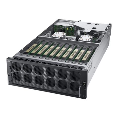
Dell EMC
Dell EMC DSS8440 Installation and service manual
W&T
W&T 53641 manual
Sun Microsystems
Sun Microsystems Netra Proxy Cache 1.0 Upgrade instructions
TYAN
TYAN GN70-B8236 Service engineer's manual

Yamaha
Yamaha MCX-2000 - MusicCAST Digital Audio Server owner's manual
