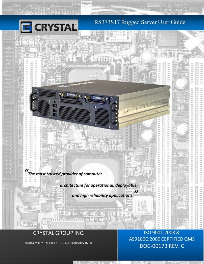
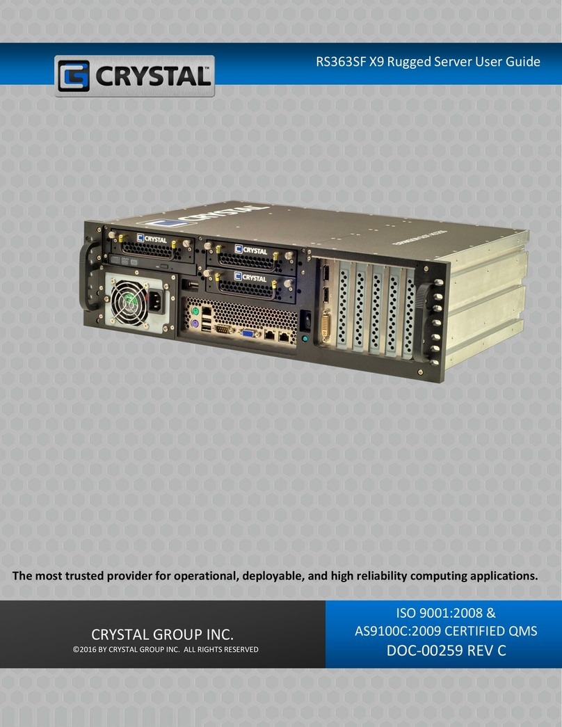
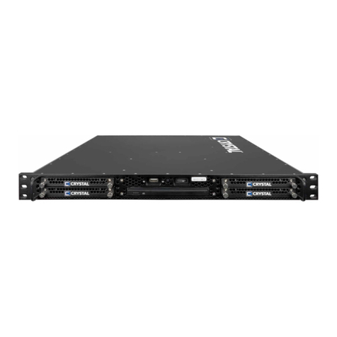
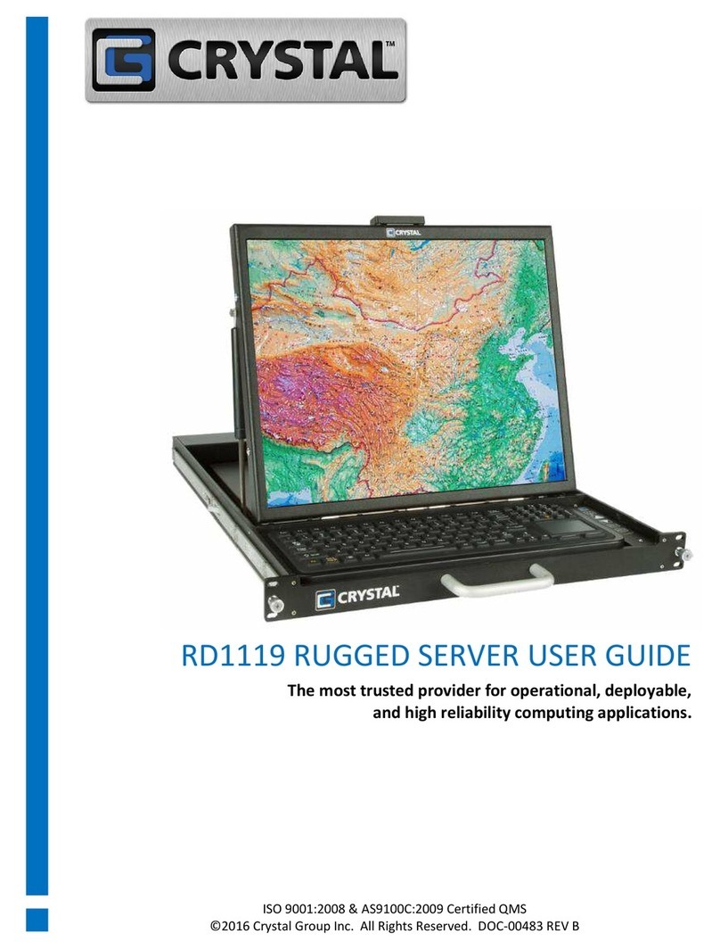
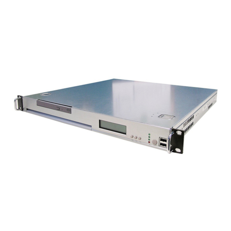
Crystal RS255 User manual

2U Rugged Servers User Guide
RS235 / RS255 / RS255L24
“The most trusted provider of computer
architecture for operational, deployable,
and high reliability applications.”
CRYSTAL GROUP INC. ISO 9001 CERTIFIED
DOC-00223 REV B
ISO 9001:2008 &
AS9100C:2009 CERTIFIED QMS
DOC-00223 REV. C

RS255, RS255L24, & RS235 Rugged Servers
Contents
After selecting a hyperlink, choose ALT and to jump back to original cursor position.
CONTENTS 1
THANK YOU 3
SAFETY 4
ADVISORIES 4
HANDLING PRECAUTIONS 5
BATTERY DISPOSAL 5
CONTACT INFORMATION 6
CUSTOMER SERVICE 6
TECHNICAL SUPPORT 6
PRODUCT INFORMATION 7
OVERVIEW 7
IDENTIFYING THE SERVER TYPE 7
SPECIFICATIONS 7
INSTALLING THE PRODUCT 10
GROUNDING
10
RACK MOUNTING PRECAUTIONS 10
INSTALLING IN AN EQUIPMENT RACK 11
OPERATING THE PRODUCT 15
CONNECTING TO THE POWER SOURCE 15
POWERING THE SERVER ON 15
MAINTAINING THE PRODUCT 16
DRIVER UPDATES 16
CHASSIS ACCESS 16
Rugged Servers Universal User Guide Page 1 of 28

RS255, RS255L24, & RS235 Rugged Servers
CHASSIS VIEWS 17
EXPANSION CARD REMOVAL AND REPLACEMENT 20
HARD DRIVE REMOVAL AND REPLACEMENT 22
MEMORY REMOVAL AND REPLACEMENT 23
TROUBLESHOOTING
25
AVAILABLE WARRANTY 26
CRYSTAL GROUP LIMITED WARRANTY 26
LEGAL INFORMATION 27
COPYRIGHTS AND TRADEMARKS 28
DESTINATION CONTROL NOTICE 28
DISCLAIMERS
28
CERTIFICATIONS AND LICENSES 28
Rugged Servers Universal User Guide Page 2 of 28

RS255, RS255L24, & RS235 Rugged Servers
We Thank You!
From all of us at Crystal Group Inc., THANK YOU for your purchase. Our customers are
the lifeline that keeps Crystal going. That is why it is extremely important to us that our
customers are 100% satisfied with their product choice.
Crystal products are designed to provide superior performance and reliability in the
harshest environments. Our company is ISO-9001:2008 and AS9100C:2009 certified
QMS to show that we are dedicated to providing high quality products to our
customers.
We are confident that this server will meet or exceed your expectations for what a
rugged industrial/military computer server should accomplish. If you have any questions
or concerns, please contact us at one of the options listed in the Contact Information
section on page 6.
Rugged Servers Universal User Guide Page 3 of 28

RS255, RS255L24, & RS235 Rugged Servers
Safety
Any service should be performed by qualified service personnel. Carefully follow all
advisories and instructions in this manual to avoid causing any bodily injury or damage
to the unit. This product does not contain any user serviceable parts.
ADVISORIES
Three types of advisories are used throughout this manual to emphasize important
information or to warn of potential hazards to the user or equipment. These advisories
each have a specific icon that will stand for one of the following: Note, Warning or
Caution. An example of each is shown below:
NOTE
A note indicates important information that helps make better use of the equipment.
WARNING
A warning indicates a potential for property damage, personal injury, or death.
CAUTION
Caution indicates potential damage to hardware or loss of data if instructions are not
followed.
Rugged Servers Universal User Guide Page 4 of 28

RS255, RS255L24, & RS235 Rugged Servers
HANDLING PRECAUTIONS
This product has components that may be damaged by electrostatic discharge (ESD).
Electrostatic Discharge (ESD)
To protect the equipment from electrostatic discharge, observe the following
precautions when handling or storing the equipment or its components:
1.
Always use a grounded wrist strap at the workstation or ground frequently by touching
the metal chassis of the system before handling any components. The chassis must be
connected to an earth ground.
2.
Use antistatic padding on all work surfaces.
3.
Avoid static-inducing carpet areas.
4.
Keep the electronic components in its static shield bag until ready to perform installation
or after removing it from the server.
5.
Always handle the memory or expansion cards by the edges.
6.
Do not touch the input/output connector pins.
BATTERY DISPOSAL
The following applies to any battery that might be on any board installed in the
equipment:
Danger of explosion if battery is incorrectly replaced.
Replace only with the same or equivalent type recommended by the manufacturer.
Dispose of used batteries according to the manufacturer’s instructions.
Rugged Servers Universal User Guide Page 5 of 28

RS255, RS255L24, & RS235 Rugged Servers
Contact Information
Crystal’s highly trained technical support personnel are dedicated to the service and
support of Crystal’s customers. Our technical personnel are acutely aware that downtime
experienced by a customer is a mission critical event. They excel at providing timely and
effective responses to any technical issues encountered in the field. Please contact us
with any questions or concerns by using one of the options below:
Customer Service Hours of Operation:
8:00 AM - 5:00 PM Monday through Friday Central Standard Time.
Technical Support Assistance Availability:
7/24/365- 7 days a week; 24 hours a day; 365 days a year.
After hours messaging service is available with a less than 30-minutes response
time.
Within the United States: 800-378-1636
International Number: 1+319-378-1636
Email Address: support@crystalrugged.com
Request a Form Under Tech Support:
http://www.crystalrugged.com
For Up-to-the-minute Crystal Products Information: http://www.crystalrugged.com
Rugged Servers Universal User Guide Page 6 of 28

RS255, RS255L24, & RS235 Rugged Servers
Product Information
OVERVIEW
The Crystal RS255, RS255L24 and RS235 are compact two rack unit (R/U) computers in a
3.5” high by 17.75” wide by 20.125”(RS255 and RS235) and 24” (RS255L24) deep chassis
that is designed for use in a 19” rack mount enclosure (see section Installing the
Product for more information) or used as a stand-alone unit. Each product consists of an
aluminum chassis/enclosure, a power supply, an active motherboard, processor(s),
CD/DVD or BD, memory, and storage.
IDENTIFYING THE SERVER TYPE
Server
Rack
Units
Expansion
Slots
Drive
Bays
Modifier
Length
RS235
2
3
5
N/A
20”
RS255
2
5
5
N/A
20”
RS255L24
2
5
5
L-Long
24”
The actual number and type of expansion slots available are motherboard dependent.
SPECIFICATIONS
Mechanical
Height
ALL
3.5” (8.9 cm)
Width
ALL
17.75” (45.1 cm)
Depth
RS255 & RS235 20.125” (51.1 cm)
RS255L24
24” (61 cm)
Weight
RS255 & RS235 30-35 lbs (13.6-15.9 kg) (excludes vibe kit mods)
Rugged Servers Universal User Guide Page 7 of 28
Table 1

RS255, RS255L24, & RS235 Rugged Servers
RS255L24
35-40 lbs (15.9-18.1 kg); excludes vibe kit
mods
Electromagnetic Interference (EMI)
ALL
Environmental kits available for shock,
vibration, EMI and humidity.
Expansion Slots
RS255 & RS255L24
Five low profile slots; combinations are
configuration dependent
RS235
Three low profile slots; combinations are
configuration dependent
Drive Options
ALL
Standard
One CD/DVD (R/W) or Blu-ray
Standard
Five removable SATA or SAS 2.5” or 3.5” HDD
Option 1
Ten 2.5” rugged drives mounted in pairs
Cooling
ALL
High speed, high volume fans (6 + 2 PS)
Thermostatically controlled
Mounting Options
ALL
Standard
Mounted on Delrin glides
Option 1
Fixed mount, front and rear
Option 2
Jonathan rails
Power Supply Options
ALL
Standard
120/240 VAC W/PFC
Option 1
28 VDC
Option 2
120/240 VAC 1+1 W/PFC
Not all MIL-STD kits are available for the above options.
Rugged Servers Universal User Guide Page 8 of 28

RS255, RS255L24, & RS235 Rugged Servers
System Board
RS255/RS235
X8DTL-3F, Socket 1366, 2-96 GB ECC Reg.
DDR3, PS/2 KB/M, DB9 Serial, VGA, 2-USB,
2-GBLAN, On-board SAS, IPMI w/ KVM over IP
RS255L24
X8DTH-6F, LGA1366 XEON, EATX, 2LAN1000,
VGA, 7 PCI-E X16 (X8 SIGNALS), IPMI, IPKVM,
SATARAIDX6, SAS 2.0 RAIDX8, SUPERMICRO
Military Standards
For a complete list of Military Standards visit the Crystal Group website at:
http://www.crystalrugged.com
Commercial Standards
Commercial standards are based on the National Electric Code (NFPA70- National Fire
Protection Association). Please visit the following link to learn more about the National Electric
Code standards:
http://www.nfpa.org
Rugged Servers Universal User Guide Page 9 of 28

RS255, RS255L24, & RS235 Rugged Servers
Installing the Product
GROUNDING
AC Version- to ensure a good earth ground, the product should be used with a UL listed
three-conductor power cord connected to a three-conductor grounded power source.
DC Version- input installations- use only approved copper connectors.
Reliable Grounding- reliable grounding of rack mounted equipment should be
maintained. Particular attention should be given to supply connections other than direct
connections to the branch circuit (e.g., use of power strips). Please see Figure 5 on page
17 for an example image of a ground stud.
RACK MOUNTING PRECAUTIONS
To prevent bodily injury when mounting or servicing this unit in a rack, special
precautions must be taken to ensure that the system remains stable. The following
guidelines are provided to ensure personal safety:
If using an equipment rack, make sure to securely bolt the rack frame to the floor or
vehicle.
Elevated Operating Ambient Temperature- if installed in a closed or multi-unit rack
assembly, the operating ambient temperature of the rack contents may be greater than
room ambient. Therefore, consideration should be given to installing the equipment in
an environmentally compatible rack with the manufacturer's maximum rated ambient
temperature.
Reduced Air Flow- installation of the equipment in a rack should be such that the air flow
is not restricted.
Mechanical Loading- mounting of the equipment in the rack should be such that a
hazardous condition is not created due to uneven mechanical loading.
Circuit Overloading- consideration should be given to how the equipment will be
connected to a supply circuit and the effect that the loading of circuits might have on
overcurrent protection and supply wiring. Appropriate consideration of the equipment
ratings should be used when addressing this concern.
All electrical wiring should be in accordance with the National Electric Code, or prevailing
Military Standards.
Rugged Servers Universal User Guide Page 10 of 28

1
4
2
The image shown
may not depict the
product received.
3
RS255, RS255L24, & RS235 Rugged Servers
INSTALLING THE PRODUCT IN AN EQUIPMENT RACK
Using Fixed Mounting Brackets
To install the equipment with fixed mounting brackets in an equipment rack, complete
the steps and see Figure 1 below:
1.
Line up holes on the sides of the rear mounting brackets with holes on the sides of the
chassis and secure with the 8-32 x 0.375” screws provided (see #2 in Figure 1). Keep
brackets level with the top of the chassis.
It may not be possible to line up all holes. If more than three holes do not line up on
each side, please contact Technical Support.
2.
Line up four holes on the front mounting ears at the desired level on the front of the
equipment rack, and attach to the rack using four (two per side) 10-32 x 0.75”rack screws
provided (see #3 in Figure 1).
3.
Line up four holes on the rear mounting ears at the desired level on the rear of the
equipment rack, and attach to the rack using four (two per side) 10-32 x 0.50” rack screws
provided (see #4 in Figure 1).
Fixed Mounting Brackets Parts List
ITEM
DESCRIPTION
1
MOUNTING EAR, EXTENDED SLOT
2
SCREW, 8-32 X 0.375”, 82D PHL FH, SS
3
SCREW, PHIL TRUSS HEAD 10-32 X 0.75"
4
SCREW, PHIL TRUSS HEAD 10-32 X 0.50”
Rugged Servers Universal User Guide Page 11 of 28
Table 2
Figure 1. Fixed Mounting Brackets

2
5
5
1
3 –CONNECTED TO
RAIL WHEN RECEIVED
6
6
4
5
5
Figure 2. Crystal Slides
4
Not all chassis support Crystal
Slides
RS255, RS255L24, & RS235 Rugged Servers
Using Crystal Slides
To install the equipment with Crystal Slides in an equipment rack, complete the following
steps and see Figure 2 below:
1.
Loosen adjuster screws.
2.
Line up the top and bottom holes on the front & rear mounting ears at the desired level
of the equipment rack, and attach to the rack using four (two per side) 10-32 x 0.50”rack
screws provided (see #1, #2 and #5 in Figure 2).
It may not be possible to line up all holes. If more than three holes do not line up, please
contact Technical Support.
3.
Tighten adjuster screws.
4.
Line up the server side slots with the slides and gently push to install in the rack.
5.
To secure the server when transporting or when extension of server is not necessary,
screw two 10-32 x 0.75” screws into the middle hole of the front bracket ears (see #1 and
#4).
Crystal Slides Parts List
ITEM
DESCRIPTION
1
FRONT MOUNTING EAR, SLIDE
2
REAR MOUNTING EAR, SLIDE
3
GUIDEBAR, T-SLOT SLIDE
4
SCREW, PHIL TRUSS HEAD 10-32 X 0.75”
5
SCREW, PHIL TRUSS HEAD 10-32 X 0.50”
6
SCREW, 8-32 X 0.375” FHD 82D, SS
Rugged Servers Universal User Guide Page 12 of 28
Table 3

RS255, RS255L24, & RS235 Rugged Servers
Using Jonathan Rails
To install the equipment with Jonathan Rails in an equipment rack, complete the
following steps below and see Figure 3 on the following page.
1.
Attach a bracket (see #6 in Figure 3) to the smooth side of the Jonathan rail that has four
or more holes in a row (see #9 in Figure 3). There are five slots on each bracket; when
attaching to the rail side with the row of holes, place the first screw in the second slit back
from the ear. Make sure the arrow marking is pointing downward.
2.
Slowly extend the rail to see the screw access hole that will allow attachment of the four
8-32 x 0.313”screws with four 8-32 X 0.344”keps nuts (see #10 in Figure 3). Place a screw
in the first hole and slide the rail to the next hole to insert a screw. Continue until all four
screws have been inserted. If the rail slides too far before placing a screw in one of the
holes, it may lock into position. Unlock rail by pressing down on the lock mechanism (see
#11 in Figure 3).
3.
Rail should be fully extended after placing the four screws in the holes and securing to
the bracket.
4.
Set the appropriate length and attach two 8-32 x 0.313”screws with two kep nuts in the
two longer slits provided. Make sure the arrow marking is pointed downward. Keep rail
fully extended (see #’s 1 & 2 in Figure 3).
5.
Repeat steps 1-4 for the second rail.
6.
With rails fully extended, locate the four holes used to attach the rails to each side of the
server. Make sure the rails are positioned with the arrow markings pointed downward.
7.
Secure to the server using four 8-32 x 0.313”screws for each side. Make sure the rail is
level with the top of the server.
8.
An assistant may be needed: Attach the server into the rack mount by screwing eight
10-32 x 0.50”screws into the top and bottom holes of the bracket ears (two for front
right; two for front left; two for back right and two for back left bracket holes) (see #’s 3,
6, 7 in Figure 3).
9.
To secure the server when transporting or when extension of server is not necessary,
screw two 10-32 x 1” screws in the middle hole on the front bracket ears (see #4 in Figure
3).
The images on the following page may not depict the product received.
Rugged Servers Universal User Guide Page 13 of 28

RS255, RS255L24, & RS235 Rugged Servers
Rugged Servers Universal User Guide Page 14 of 28
Table 4
Jonathan Rails Parts List
ITEM
DESCRIPTION
1
SCREW, PHIL FHD 100D 8-32 X 0.313”, SS
2
KEPS NUT, 8-32 X 0.344” HEAD STL
3
SCREW, PHIL TRUSS HEAD 10-32 X 0.50”
4
SCREW, PHIL TRUSS HEAD 10-32 X 1”
5
SLIDE RAILS, 20”, LOCKING, JONATHAN 128QD-20
6
BRACKET, RH, RACK MOUNT
7
BRACKET, LH, RACK MOUNT
8
ARROW MARK (2 ON EACH RAIL)
9
ROW OF HOLES (ATLEAST 4 ON EACH RAIL)
10
SCREW ACCESS HOLE (1 ON EACH RAIL)
11
LOCK MECHANISM (1 ON EACH RAIL)
12
LOCK MECHANISM (2 ON EACH RAIL)
13
FOUR HOLES (2 ROWS OF 2- 4 ON EACH RAIL)
Not all chassis support Jonathan Rails
9
Extended Views
7
Closed Views with Brackets
5
5
4
3
6
9
6
1
2
7
8
1
2
3
Figure 3. Jonathan Rails

RS255, RS255L24, & RS235 Rugged Servers
Operating the Product
If the product is part of a rack configuration, refer to the rack user’s guide for more
information on connecting to a power source.
CONNECTING TO A POWER SOURCE
Please see Installing the Product on page 10 for more information.
POWERING THE SERVER ON
After securely attaching the power connection, press the Power On/Off switch which will
be located on either the front or the back of the chassis depending on the specific
configuration. A blue LED will illuminate when power is applied (see Figure 4, page 17
for location of power switch and more information about the product chassis).
Rugged Servers Universal User Guide Page 15 of 28

RS255, RS255L24, & RS235 Rugged Servers
Maintaining the Product
Only qualified service personnel should attempt to open the product chassis.There
are not any user serviceable parts inside.
To protect the equipment from Electrostatic Damage (ESD), follow the proper
precautions at all times when handling the unit and its components. Please see
Electrostatic Discharge section on Page 5.
DRIVER UPDATES
Contact Technical Support at one of the options listed on page 6.
CHASSIS ACCESS
Removing the Cover
1.
Ensure the equipment is powered off and the unit is disconnected from the power source.
2.
Remove the screws connecting the top covers (there may be a separate cover over the
Expansion Slot Access area) to the chassis using a Phillips screw driver.
3.
Lift the covers to expose the interior of the chassis.
Rugged Servers Universal User Guide Page 16 of 28

RS255, RS255L24, & RS235 Rugged Servers
CHASSIS VIEWS:
Figure 4. Front View RS255, RS255L24, & RS235
EXPANSION SLOTS
Figure 5. Rear View RS255 & RS255L24
The images above may not depict the product received.
Rugged Servers Universal User Guide Page 17 of 28
USB 1
POWER
USB 2
POWER SWITCH
DRIVE BAYS 1 & 2
DRIVE BAY 5
CD/DVD/BD
DRIVE BAYS 3 & 4
TAPPED
HOLE
FAN ASSEMBLY
GROUNDING STUD
POWER SUPPLY
CONNECTION
I/O PORTS

RS255, RS255L24, & RS235 Rugged Servers
CHASSIS VIEWS CONTINUED:
Figure 6. Rear View RS235
The image above may not depict the product received.
Rugged Servers Universal User Guide Page 18 of 28
FAN ASSEMBLY
GROUNDING STUD
POWER SUPPLY
CONNECTION
I/O PORTS
EXPANSION SLOTS

RS255, RS255L24, & RS235 Rugged Servers
Input/output (I/O) Ports:
Figure 7. I/O Ports
NUMBER
FUNCTION
1
PS/2 KEYBOARD
2
PS/2 MOUSE
3
USB PORT 3
4
USB PORT 4
5
USB PORT 5
6
USB PORT 6
7
COM PORT 1
8
COM PORT 2
9
GIGABIT LAN PORT 1
10
GIGABIT LAN PORT 2
11
LINE-IN
12
LINE-OUT
13
MIC-IN
14
VGA PORT
15
REMOTE MANAGEMENT PORT
The product received will have one of the three I/O ports shown in Figure 7.
Rugged Servers Universal User Guide Page 19 of 28
X8DTL- 3F & X8DTH-6F
X7DVL-E
X7DAL-E
Table 5
This manual suits for next models
2
Table of contents
Other Crystal Server manuals
Popular Server manuals by other brands
Gigabyte
Gigabyte R261-3C0 user manual
Sun Microsystems
Sun Microsystems Sun Blade T6300 installation guide
Asus
Asus Motherboard AP130-E1 user guide
Sun Microsystems
Sun Microsystems Fire X4600 Service manual

Sun Microsystems
Sun Microsystems Sun Enterprise 220R owner's guide
Meinberg
Meinberg IMS-M3000 manual
