Peristaltic Pump Operating Instructions
High Quality Groundwater and Surface Water Monitoring Instrumentation
(Page 1 of 2)
Model 410
®Solinst is a registered trademark of Solinst Canada Ltd.
IMPORTANT
• The pump should be operated in an upright position, sitting on the
rubber feet on the bottom of the pump (handle and dial on top).
• Pump is water resistant but not waterproof. Do not submerge in
water.
• Pump is not designed for long-term continuous uninterrupted use.
• To avoid motor damage due to over-heating, allow pump to cool
fully at least every 7–8 hours, or more often under high ambient heat
conditions.
• Pumping rates will decrease with elevation, and as the amount of lift
increases.
• Replace the tubing regularly. Worn tubing can cause the pump to be
inefficient. This will show as a limited ability to lift water. If the tubing
looks worn, flattened or cracked, replace the tubing.
• If used in cold weather, ensure that there is no ice in the tubing before
starting the pump.
Power
The pump operates from an external 12V DC power supply such
as a car, truck or marine 12 volt battery that can supply at least
3–5 amps at maximum draw. The pump has a 12 ft (3.6 m) power cable with
connector clips for direct battery connection.
The power cable clips are oversized for use with automotive batteries. The
red clip connects to the positive (+) battery terminal, black to negative (-)
battery terminal. If the battery is connected with reverse polarity the pump
will not be harmed, but it will NOT operate until the polarity is connected
correctly.
A circuit breaker reset button is located on the side of the pump. In the event
the pump amperage exceeds 10 amps, the circuit breaker will trip (button
pops out) and turn the pump off. To reset the breaker, simply press the reset
button back in to regain operation of the pump.
If the pump is to be powered by a typical 45Ah vehicle battery for more
than 3 continuous hours, start vehicle and run for 15 minutes to recharge
the battery.
Continued overleaf...
Down-hole Tubing Specications
Use with Standard 5/8" OD Silicon Tubing
1/2" OD x 3/8" ID LDPE (100 ft coil) 109490
1/2" OD x 3/8" ID LDPE (250 ft coil) 109489
1/2" OD x 3/8" ID LDPE (500 ft coil) 109488
Use with Optional 3/8” OD (with Adaptor Kit) Silicon Tubing
1/4" OD x 0.17" ID LDPE Tubing (100 ft coil) 109465
1/4" OD x 0.17" ID LDPE Tubing (250 ft coil) 109464
1/4" OD x 0.17" ID LDPE Tubing (500 ft coil) 109463
1/4" OD x 0.17" ID PTFE-lined LDPE Tubing (100 ft coil) 109454
1/4" OD x 0.17" ID PTFE-lined LDPE Tubing (250 ft coil) 109444
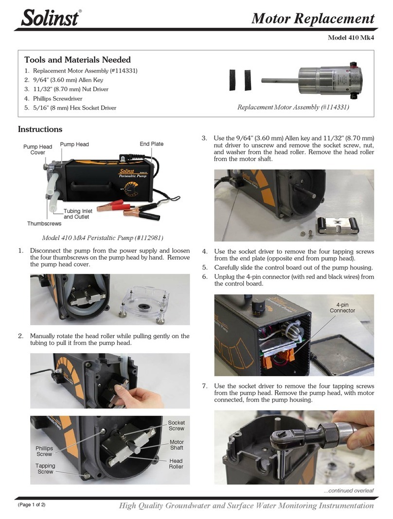
Model 410 Peristaltic Pump (#112981)
Reset Button Power Cable
Dial
Thumbscrews
Pump Head Handle
5/8"
Silicone
Tubing
Peristaltic Pump
Model 410
Model 410 Peristaltic Pump Setup
Extra tubing may be connected,
or the sample can just discharge
out of the pump head tubing
Down-hole tubing is inserted
inside the pump head tubing by
about 1" (25 mm). The friction-
t holds the tubing together.
Pump Head Tubing
(5/8" or 3/8")
Down-hole Tubing
(1/2" or 1/4")
Operation
• The Solinst Peristaltic Pump has an integral forward/reverse, variable
flow dial with an OFF position, which has a central detent. When turning
the unit OFF, ensure you feel the dial snap into position.
• The pump should always be kept with the control in the OFF position
when it is being attached to a power source or stored.
• Once attached to a power source, turn the dial in the direction required
and adjust the flow as desired.
• The standard 5/8" (16 mm) OD medical grade silicone tubing can be
attached to 1/2" (13 mm) OD down-hole sample tubing and gives purge
rates up to 3.5 L/min and 120 mL/min at the low end.
• The 3/8" (10 mm) OD silicone tubing and adaptor kit allows the use
of 1/4" (6 mm) OD down-hole sample tubing, giving flow rates up to
900 mL/min and sampling rates as low as 40 mL/min.
1. Ensure that the chosen silicone tubing has been properly installed in the
pump head.
2. Connect one end of the silicone tubing to the down-hole sample line.
See diagram below.
3. Either connect the other end of the silicone tubing to a discharge tube,
or simply discharge out of this end of the tubing. See diagram below.
4. Connect the negative (black) battery clip to the negative terminal post
on a 12V DC battery and the positive (red) battery clip to the positive
terminal.
5. Turn the dial in the direction required and adjust the flow as desired.


