Solinst 415 User manual
12V Submersible Pump Operating Instructions
High Quality Groundwater and Surface Water Monitoring Instrumentation
(Page 1 of 3)
Model 415
®Solinst is a registered trademark of Solinst Canada Ltd.
SAFETY INSTRUCTIONS
• The 12V Pump Controller can get warm. It is set to turn off
at 65ºC.
• Do not block the fan intake or exhaust vent during operation
of the 12V Pump Controller.
• Do not touch the inside of the 12V Submersible Pump after
it has been running – the motor module gets extremely hot.
• This 12V Submersible Pump is to only be used for
groundwater purging/sampling.
• The 12V Pump Controller is water resistant but not
waterproof. Do not submerge in water.
• Do not use the 12V Pump Controller near flammable liquids
or gases.
• The 12V Submersible Pump is designed to operate when
submerged only.
• The Solinst Model 415 12V Controller is only designed to
work with the Solinst Model 415 12V Submersible Pump.
Power Supply
The 12V Pump Controller operates from an external 12 volt
DC power supply such as a car, truck or marine 12 volt battery
that can supply up to 45 amps at maximum draw. The Pump
Controller has a 2.3 m (7.5 ft) power cable with connector clips
for direct battery connection.
The power cable clips are oversized for use with automotive
batteries. The red clip connects to the positive (+) battery
terminal, black to negative (-) battery terminal. If the battery
is connected with reverse polarity the Controller will not be
harmed, but it will NOT operate until the polarity is connected
correctly (the LED on the Pump Controller will remain off with
reverse polarity).
A circuit breaker reset button is located on the side of the Pump
Controller. In the event the amperage exceeds 50 amps, the
circuit breaker will trip (button pops out) and turn the Controller
off. To reset the breaker, turn the dial to “0” then press the
reset button back in to regain operation.
If the Pump is to be powered by a typical 45Ah vehicle battery,
start the vehicle and run for 15 minutes to recharge the battery,
then restart the vehicle every 15 minutes for 5 minutes to
maintain the battery power during sampling.
Operation
• The Pump Controller should always be kept with the dial
in the OFF position when it is being attached to a power
source or stored.
• The Pump Controller dial is used to adjust the flow of
water being discharged. As you increase the dial, so does
the Controller’s voltage output. This will enable the Pump
motor to spin faster, therefore, increasing the flow of water
being discharged. To slow the flow of water, turn the dial
counter-clockwise.
• When the dial is in the OFF position the Controller will
produce 0 volts, in the highest position “10” the Controller
will output 25 volts.
• The Controller has a low voltage disconnect at 10 volts as
indicated by the slowly flashing yellow light. (However, the
Controller can disconnect at a higher voltage if the Pump’s
current increases, e.g. if the Pump is running at maximum
current (20 amps), the battery can disconnect at 11.7 volts.)
The Controller will shut off and then turn on every few
seconds (pulsate) or the water flow from the Pump will slow
if the output voltage on the battery drops to 10.75 volts
when in use. Stop operation, disconnect the power, and
recharge the battery.
1. Connect the negative (black) battery clip to the negative
terminal post on a 12 volt DC battery and the positive (red)
battery clip to the positive terminal.
2. Connect the Pump’s cable to the connector cable from the
Pump Controller.
3. Connect the 3/8" ID tubing to the Pump. Ensure the
tubing is pushed all the way onto the tubing barb.
4. Lower the Pump to the required sampling depth. Use
a safety line connected to the eyebolt on the top of the
Pump, if desired (such as a Model 103 Tag Line).
5. Turn the dial to adjust the flow as desired.
Maximum Flow Rate Estimates
Depth to Water Flow Rate
30 ft (10 m) 12.5 L/min
40 ft (12 m) 11.0 L/min
50 ft (15 m) 9.5 L/min
70 ft (21 m) 7.5 L/min
80 ft (24 m) 6.0 L/min
100 ft (30 m) 4.25 L/min
110 ft (33.5 m) 1.5 L/min
Tubing Specications
1/2" OD x 3/8" ID LDPE (100 ft coil) 109490
1/2" OD x 3/8" ID LDPE (250 ft coil) 109489
1/2" OD x 3/8" ID LDPE (500 ft coil) 109488
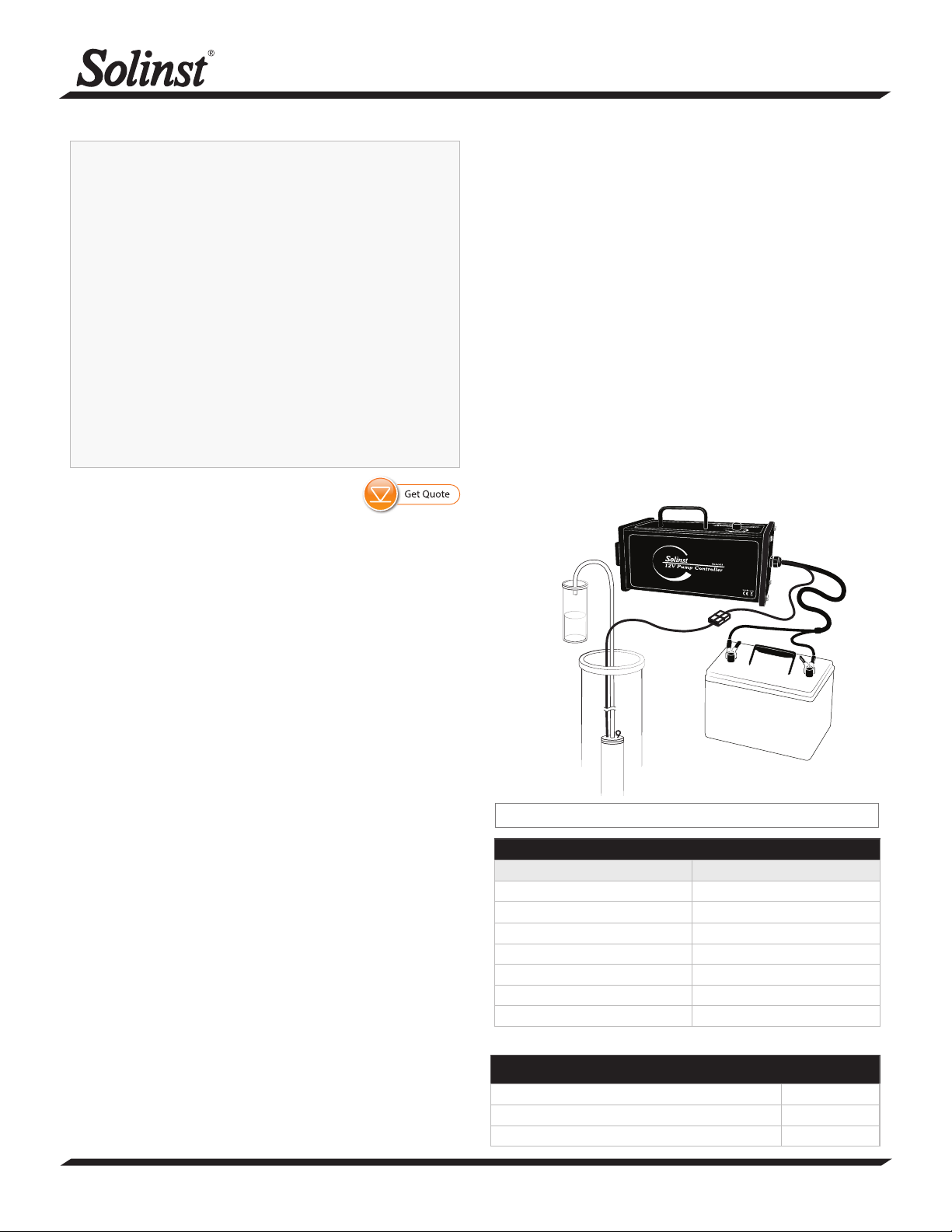
Battery
Pump
Sample
12V Pump
Controller
Note: See Model 415 12V Submersible Pump data sheet for full pump curve.
Note: See Page 3 for dedicated set up using a 2” Well Cap Assembly.
More Info | Instructions | Get Quote

High Quality Groundwater and Surface Water Monitoring Instrumentation
12V Submersible Pump Operating Instructions
(Page 2 of 3)
Troubleshooting
If the Pump or Controller fail to work, please try the following:
• Make sure the Pump is submerged and properly connected
to the Controller.
• Make sure the Controller is properly connected to the power
source (LED lights will remain off with reverse polarity).
• Try resetting the circuit breaker by pushing the button back
into the Controller.
• Make sure the Controller dial is turned all the way up to
position 10 (turned clockwise all the way until it stops).
• Check the LED lights to see if they are indicating high or
low battery voltage.
• Check the battery voltage, it must be 12.5 volts minimum:
The Controller has a low voltage disconnect at 10 volts.
The Controller will shut off and then turn on every few
seconds (pulsate) or the water flow from the Pump will
slow if the output voltage on the battery drops to 10.75
volts when in use. The Controller has a high voltage
disconnect at 18 volts.
• A fast flashing red LED indicates an electrical continuity
issue. Check voltage and all connections.
• Make sure the Pump is operational. The Pump can overload
if the impeller is blocked with sediments.
LED Indicator Light Denitions
LED Condition
Cycling colours: Pump OFF
Solid green: Pump ON
Flashing green: Pumping at Maximum Rate
Slow ashing yellow: Charge Battery
Fast ashing yellow: Voltage Too High
Solid red: Stop Pump. Service Required.
Slow ashing red: Controller Cool-down Required
Fast ashing red: Pump is Disconnected
Pump Maintenance
• The Pump can run as long as the motor is submerged
and battery power is available. Running the motor dry will
reduce its life. If Pump runs for very long time then the
motor will not last.
• In the event of a tripped circuit breaker, turn the
Controller dial to the “0” position, then press the reset
button and slowly turn the dial to desired setting.
• Use the optional disposable filter to prevent sediments
from entering the Pump motor.
Decontamination
• To decontaminate the Pump, always follow your local
guidelines and protocols.
• DO NOT fully disassemble the Pump.
1. Unscrew intake or filter from the bottom of the Pump.
2. Wash the Pump with a phosphate-free soap.
3. Rinse thoroughly with deionized water and dry.
4. Reconnect the intake or a new filter.
800M Mini Pneumatic Packer Connection
(suitable for 50 mm (2" OD) Schd 40 wells)
1. Unscrew the intake/filter from the bottom of the Pump.
2. Screw the Pump to Packer Adaptor into the bottom of the
Pump until finger tight.
3. Screw the 800M Packer Assembly into the bottom of the
Pump to Packer Adaptor. (See the Model 800M Assembly
and Installation Instructions).
4. Lower the assembly to the desired depth.
5. Inflate the Packer Assembly as described in the 800M
Assembly and Installation Instructions and operate the
12V Pump in the same manner as described on Page 1.
Optional Disposable Filter
( #115774 100 US mesh sieve size)
Pump Intake
Pump to Packer Adaptor
(#115939)
800M Mini Single Packer Assembly
(#115931)
Note: All “Red” faults require the Controller to be turned off, wait 10
seconds, and turn it back on to clear the indicator. Exception: if
the Controller is overheated, then turn the dial to near “0” but
keep the unit powered to let the fan provide airflow for cooling.
Sample Inlet
Filter Installation
1. Unscrew the intake from the bottom of the Pump.
2. Screw the filter into the bottom of the Pump until finger
tight.
Slow: 1 ash per second Fast: 4 ashes per second

Solinst Canada Ltd. 35 Todd Road, Georgetown, Ontario Canada L7G 4R8 www.solinst.com
E-mail: instruments@solinst.com Tel: +1 (905) 873-2255; (800) 661-2023 Fax: +1 (905) 873-1992
January 11, 2022
(#116057) (Page 3 of 3)
2" Dedicated Well Cap Assembly (#116244)
Includes the Well Cap Base, Cap, Insert and Support Hanger
Bracket (4" Adaptor also available (#110235))
1. Wrap the top end of the Pump cable around the support
hanger bracket, inserting the cable into the cutouts of the
bracket to secure. Leave about 3” of slack in the Pump cable
(top end has connectors for the Controller) above the top of the
bracket.
Note: The holes in the bracket can accommodate twist ties or zip ties to
secure the cable to the bracket, if desired.
2. Just above the hanger bracket, slip the Pump cable through
the pass-through in the side of the well cap insert and into the
opening (tubing pushfit connection on the insert facing up).
Line up the insert with the hanger bracket, to avoid twisting
the cable.
3. Connect the sample tubing from the Pump to the tubing barb
on the bottom of the well cap insert. Ensure the tubing is
pushed all the way onto the tubing barb.
4. Slide the well cap base onto the well casing.
5. Lower the pump assembly down the well until the support
hanger bracket seats on the shoulder of the well cap base.
6. Push a short length of 3/8" OD sample tubing into the pushfit
connection on the top of the well cap.
7. Connect the Controller to the Pump cable connector and
operate the 12V Pump in the same manner as described on
Page 1.
Note: While sampling, the red plug can be removed from the opening in the
well cap insert to accommodate other monitoring equipment, such as
a Solinst Water Level Meter or Levelogger.
8. Once finished sampling, release the sample tubing from the
pushfit connection by pushing down on both sides of the top
ring and pull the tubing out.
9. Secure the well cap to the well cap base. Attach an optional
padlock if needed.
Sample Tubing
Pusht Connection
Pass-through for
Pump Cable
Well Cap Base
Well
Cap
Insert
Opening for
Monitoring
Equipment
3/8" OD
Sample Tubing
Pump Cable
(130 ft, 100 ft, 75 ft,
50 ft & 25 ft lengths
available)
Support Hanger
Bracket Sample Tubing
Pump Cable
Connector
Controller
Connector
Eyebolt
Sample Tubing
Barb
Other Solinst Water Pump manuals


Popular Water Pump manuals by other brands


Sykes AmeriPumps
Sykes AmeriPumps GP100M Operation and maintenance instructions

DUROMAX
DUROMAX XP WX Series user manual

BRINKMANN PUMPS
BRINKMANN PUMPS SBF550 operating instructions

Franklin Electric
Franklin Electric IPS Installation & operation manual

Xylem
Xylem e-1532 Series instruction manual

Milton Roy
Milton Roy PRIMEROYAL instruction manual