TEXEL MEP User manual

Texel
Magnetic Drive Pump
Operation
Manual

Thank you for purchasing Texel Corrosion Resistant Pump.
Although the pump is designed and manufactured for applications in which corrosion resistance is a priority, modifications
in operating conditions or improper operations may result in unexpected incidents.
It is requested that the user read this operation manual thoroughly and use the product in a proper manner.
Contents
1.
Things to be confirmed upon arrival................................ 6
2.
For the safety ..................................................................... 6
2.1.
Transportation ................................................................ 6
2.2.
Confirmation................................................................... 6
2.3.
Application...................................................................... 6
3.
Storage ............................................................................... 6
3.1.
Short-term storage (less than three months).................. 6
3.2.
Long-term storage (more than three months)................. 6
4.
Installation and piping....................................................... 7
4.1.
Installation ...................................................................... 7
4.2.
Piping ......................................................................... 7
4.2.1.
Piping load (common for all models) ................ 7
4.2.2.
Suction piping (other than MES type) (Fig.
4-4)................................................................... 7
4.2.3.
Discharge piping (other than MES type)........... 8
4.2.4.
Suction piping (MES type) (Fig. 4-4)................. 8
4.2.5.
Discharge piping (MES type) (Fig. 4-3) ............ 8
4.2.6
Motor wiring...................................................... 8
5.
Notes on handling............................................................ 11
5.1.
Notes on the start-up.................................................... 11
5.2.
Notes on the operation................................................. 11
5.3.
Notes on stopping ........................................................ 12
5.4.
Notes operational interruption ...................................... 12
5.5.
Notes on the motor....................................................... 12
5.6.
Notes on the ambient temperature............................... 12
5.7.
Notes on the fluid ......................................................... 12
5.8.
Others .......................................................................... 12
5.9.
Ordering spare parts .................................................... 12
6.
MER type .......................................................................... 13
6.1.
Construction and parts name ....................................... 13
6.2.
Maintenance and inspection......................................... 14
6.2.1.
Routine inspection.......................................... 14
6.2.2.
Regular inspection.......................................... 14
6.2.3.
Abrasive limit of the bearing ........................... 14
6.3.
Disassembling & assembling ....................................... 15
6.3.1.
Notes on disassembling ................................. 15
6.3.2.
Preparation for disassembling ........................ 15
6.3.3.
Disassembling ................................................ 15
6.3.4.
Assembling..................................................... 16
6.3.5.
Replacement of the motor and outer magnet . 16
6.3.6.
Replacement of the main shaft and front
thrust .............................................................. 17
6.3.7.
Replacement of the front bearing ................... 17
6.3.8.
Replacement of the rear bearing and the
rear thrust....................................................... 17
6.3.9.
Replacement of the casing and casing cover . 18
7.
MEH-040 type ................................................................... 19
7.1.
Construction and parts name ....................................... 19
7.2.
Maintenance and inspection......................................... 20
7.2.1.
Routine inspection.......................................... 20
7.2.2.
Regular inspection.......................................... 20
7.2.3.
Abrasive limit of the bearing ........................... 20
7.3.
Disassembling & assembling ....................................... 21
7.3.1.
Notes on disassembling ................................. 21
7.3.2.
Preparation for disassembling ........................ 21
7.3.3.
Disassembling ................................................ 22
7.3.4.
Assembling..................................................... 22
7.3.5.
Replacement of the motor and outer magnet . 23
7.3.6.
Removing and replacing the main shaft ......... 23
7.3.7.
Replacement of bearing ................................. 24
7.3.8.
Replacement of the mouth ring and
front/rear thrust rings...................................... 24
7.3.9.
Replacement of the casing and casing cover. 24
8.
MTA-040/080/100 type...................................................... 25
8.1.
Construction and parts name ....................................... 25
8.2.
Maintenance and inspection ........................................ 26
8.2.1.
Routine inspection.......................................... 26
8.2.2.
Regular inspection.......................................... 26
8.2.3.
Abrasive limit of the bearing ........................... 26
8.3.
Disassembling & assembling ....................................... 27
8.3.1.
Notes on disassembling ................................. 27
8.3.2.
Preparation for disassembling ........................ 27
8.3.3.
Disassembling ................................................ 28
8.3.4.
Assembling..................................................... 29
8.3.5.
Replacement of the motor and outer magnet . 29
8.3.6.
Removing and replacing the main shaft ......... 29
8.3.7.
Replacement of bearing ................................. 30
8.3.8.
Replacement of the mouth ring and the
front/rear thrust rings...................................... 30
8.3.9.
Replacement of the shaft support................... 30
9.
MTA-101/125/150 type...................................................... 31
9.1.
Construction and parts name ....................................... 31
9.2.
Maintenance and inspection ........................................ 32
9.2.1.
Routine inspection.......................................... 32
9.2.2.
Regular inspection.......................................... 32
9.2.3.
Abrasive limit of the bearing ........................... 32
9.3.
Disassembling & assembling ....................................... 33
9.3.1.
Notes on disassembling ................................. 33
9.3.2.
Preparation for disassembling ........................ 33
9.3.3.
Disassembling ................................................ 34
9.3.4.
Assembling..................................................... 35
9.3.5.
Replacement of the motor and outer magnet . 35
9.3.6.
Removing and replacing the main shaft ......... 36
9.3.7.
Replacement of bearing ................................. 36
9.3.8.
Replacement of the mouth ring and the
front/rear thrust rings...................................... 36
9.3.9.
Replacement of the shaft support................... 36
10.
MTA-200 type.................................................................... 37
10.1.
Construction and parts name ....................................... 37
10.2.
Maintenance and inspection ........................................ 38
10.2.1.
Routine inspection.......................................... 38
10.2.2.
Regular inspection.......................................... 38

10.2.3.
Abrasive limit of the bearing ........................... 38
10.3.
Disassembling & assembling ....................................... 39
10.3.1.
Notes on disassembling ................................. 39
10.3.2.
Preparation for disassembling ........................ 39
10.3.3.
Disassembling ................................................ 40
10.3.4.
Assembling..................................................... 41
10.3.5.
Replacement of the motor and outer magnet . 41
10.3.6.
Removing and replacing the main shaft ......... 41
10.3.7.
Replacement of bearing ................................. 41
10.3.8.
Removing and replacing the impeller ............. 42
10.3.9.
Replacement of the mouth ring and the
front/rear thrust............................................... 42
11.
MSX-100/125/150 type...................................................... 43
11.1.
Construction and parts name ....................................... 43
11.2.
Maintenance and inspection......................................... 44
11.2.1.
Routine inspection.......................................... 44
11.2.2.
Regular inspection.......................................... 44
11.2.3.
Abrasive limit of the bearing ........................... 44
11.3.
Disassembling & assembling ....................................... 45
11.3.1.
Notes on disassembling ................................. 45
11.3.2.
Preparation for disassembling ........................ 45
11.3.3.
Disassembling ................................................ 46
11.3.4.
Assembling..................................................... 47
11.3.5.
Replacement of the motor and outer magnet . 48
11.3.6.
Replacement of the front thrust ring and
mouth ring ...................................................... 49
11.3.7.
Replacement of the bearing ........................... 49
11.3.8.
Replacement of the main shaft....................... 49
12.
MET-040 type.................................................................... 50
12.1.
Construction and parts name ....................................... 50
12.2.
Maintenance and inspection......................................... 51
12.2.1.
Routine inspection.......................................... 51
12.2.2.
Regular inspection.......................................... 51
12.2.3.
Abrasive limit of the bearing ........................... 51
12.3.
Disassembling & assembling ....................................... 52
12.3.1.
Notes on disassembling ................................. 52
12.3.2.
Preparation for disassembling ........................ 52
12.3.3.
Disassembling ................................................ 53
12.3.4.
Assembling..................................................... 54
12.3.5.
Replacement of the motor and outer magnet . 54
12.3.6.
Removing and replacing the main shaft ......... 54
12.3.7.
Replacement of bearing ................................. 54
12.3.8.
Replacement of the mouth ring and the
front/rear thrust............................................... 55
13.
MET-050/080 type............................................................. 56
13.1
Construction and parts name ....................................... 56
13.1.1
MET-050 type ................................................. 56
13.1.2
MET-080 type ................................................. 57
13.2.
Maintenance and inspection......................................... 58
13.2.1.
Routine inspection.......................................... 58
13.2.2.
Regular inspection.......................................... 58
13.2.3.
Abrasive limit of the bearing ........................... 58
13.3.
Disassembling & assembling ....................................... 59
13.3.1.
Notes on disassembling ................................. 59
13.3.2.
Preparation for disassembling ........................ 59
13.3.3.
Disassembling ................................................ 60
13.3.4.
Assembling..................................................... 61
13.3.5.
Replacement of the motor and outer magnet . 61
13.3.6.
Removing and replacing the main shaft ......... 61
13.3.7.
Replacement of the front bearing (MET-050
type)............................................................... 61
13.3.8.
Replacement of the rear bearing (MET-050
type)............................................................... 62
13.3.9.
Replacement of the front bearing (MET-080
type)............................................................... 62
13.3.10.
Replacement of the rear bearing (MET-080
type)............................................................... 62
13.3.11.
Replacement of the rear thrust ring ................ 62
14.
MST-050 type.................................................................... 63
14.1.
Construction and parts name ....................................... 63
14.2.
Maintenance and inspection ........................................ 64
14.2.1.
Routine inspection.......................................... 64
14.2.2.
Regular inspection.......................................... 64
14.2.3.
Abrasive limit of the bearing ........................... 64
14.3.
Disassembling & assembling ....................................... 65
14.3.1.
Notes on disassembling ................................. 65
14.3.2.
Preparation for disassembling ........................ 65
14.3.3.
Disassembling ................................................ 65
14.3.4.
Assembling..................................................... 66
14.3.5.
Replacement of the motor and outer magnet . 67
14.3.6.
Removing and replacing the main shaft ......... 67
14.3.7.
Replacement of the bushing........................... 67
14.3.8.
Replacement of the thrust ring ....................... 67
15.
MEP-040/050 type ............................................................ 68
15.1.
Construction and parts name ....................................... 68
15.2.
Maintenance and inspection ........................................ 69
15.2.1.
Routine inspection.......................................... 69
15.2.2.
Regular inspection.......................................... 69
15.2.3.
Abrasive limit of the bearing ........................... 69
15.3.
Disassembling & assembling ....................................... 70
15.3.1.
Notes on disassembling ................................. 70
15.3.2.
Preparation for disassembling ........................ 70
15.3.3
Disassembling ................................................ 71
15.3.4.
Assembling..................................................... 71
15.3.5.
Replacement of the motor and outer magnet . 71
15.3.6
Installing and removing the impeller and
inner magnet .................................................. 72
15.3.7.
Replacement of bearing ................................. 72
15.3.8.
Replacement of the mouth ring and the
front/rear thrust rings...................................... 72
6.
MEP-080 type ................................................................... 73
16.1.
Construction and parts name ....................................... 73
16.2.
Maintenance and inspection ........................................ 74
16.2.1.
Routine inspection.......................................... 74
16.2.2.
Regular inspection.......................................... 74
16.2.3.
Abrasive limit of the bearing ........................... 74
16.3.
Disassembling & assembling ....................................... 75
16.3.1.
Notes on disassembling ................................. 75
16.3.2.
Preparation for disassembling ........................ 75
16.3.3.
Disassembling ................................................ 76
16.3.4.
Assembling..................................................... 77
16.3.5.
Installing and removing the impeller and
inner magnet .................................................. 77
16.3.6.
Replacement of bearing ................................. 77
16.3.7.
Replacement of the mouth ring and the
front/rear thrust rings...................................... 77
17.
MES-040 type ................................................................... 78
17.1.
Construction and parts name ....................................... 78
17.2.
Maintenance and inspection ........................................ 79
17.2.1.
Routine inspection.......................................... 79

17.2.2.
Regular inspection.......................................... 79
17.2.3.
Abrasive limit of the bearing ........................... 79
17.3.
Disassembling & assembling ....................................... 80
17.3.1.
Notes on disassembling ................................. 80
17.3.2.
Preparation for disassembling ........................ 80
17.3.3.
Disassembling ................................................ 81
17.3.4.
Assembling..................................................... 82
17.3.5.
Replacement of the motor and outer magnet . 82
17.3.6.
Installing and removing the impeller and
inner magnet .................................................. 82
17.3.7.
Replacement of bearing ................................. 82
17.3.8.
Replacement of the mouth ring and the
front/rear thrust rings...................................... 83
18.
MES-050 type ................................................................... 84
18.1.
Construction and parts name ....................................... 84
18.2.
Maintenance and inspection......................................... 85
18.2.1.
Routine inspection.......................................... 85
18.2.2.
Regular inspection.......................................... 85
18.2.3.
Abrasive limit of the bearing ........................... 85
18.3.
Disassembling & assembling ....................................... 86
18.3.1.
Notes on disassembling ................................. 86
18.3.2.
Preparation for disassembling ........................ 86
18.3.3.
Disassembling ................................................ 87
18.3.4.
Assembling..................................................... 88
18.3.5.
Replacement of the motor and outer magnet . 88
18.3.6.
Removing and replacing the main shaft ......... 89
18.3.7.
Replacement of the bearing ........................... 89
18.3.8.
Replacement of the mouth ring and
front/rear thrust rings...................................... 89
19.
MES-080 type ................................................................... 90
19.1.
Construction and parts name ....................................... 90
19.2.
Maintenance and inspection......................................... 91
19.2.1.
Routine inspection.......................................... 91
19.2.2.
Regular inspection.......................................... 91
19.2.3.
Abrasive limit of the bearing ........................... 91
19.3.
Disassembling & assembling ....................................... 92
19.3.1.
Notes on disassembling ................................. 92
19.3.2.
Preparation for disassembling ........................ 92
19.3.3.
Disassembling ................................................ 93
19.3.4.
Assembling..................................................... 94
19.3.5.
Replacement of the motor and outer magnet . 94
19.3.6.
Removing and replacing the main shaft ......... 94
19.3.7.
Replacement of bearing ................................. 95
19.3.8.
Replacement of the mouth ring and the
front/rear thrust rings...................................... 95
20.
Allowable piping load...................................................... 96
21.
Failure modes and their causes ..................................... 97
21.1.
Insufficient flow/pressure.............................................. 97
21.2.
Inability to hoist ............................................................ 98
21.3.
Vibration/noise ............................................................. 99
21.4.
Overcurrent ................................................................ 100
22.
References ..................................................................... 101
22.1.
Possible temperature classes of the pump................. 101
22.2.
Maximum allowable temperature ............................... 101
22.3.
Gap between the bracket and the outer magnet ........ 101
22.4.
Tightening torque for the outer magnet fastening
screws 102
22.5.
Priming time for the self-priming pumps..................... 103
22.5.1.
MES-040/050 type........................................ 103
22.5.2.
MES-080 type............................................... 104
23.
Pump label.................................................................... 1055
24. Corrrosion resistance chart…………………………….. 106
25. Contact lis………………………………………………….. 108
Indication What it means
Warning
A procedure that may
result in a death or a
serious injury if the
instruction is not
followed.
Caution
A procedure that is
expected to result in a
minor to moderate injury
or property
damage if the
instruction is not
followed.
Possible
Explosion
Indicates a danger if
used in an explosive
atmosphere.

i
Information
A procedure that is
strongly recommended
to use the product more
safely.

1. Things to be confirmed upon
arrival
Upon arrival of the pump, please check and confirm
followings.
(1) The specifications on the label on the pump match the order
specifications.
(2) All accessories are in place.
(3) All bolts and screws are securely fastened.
(4) The pump appears normal without a trace of damage during
the transportation.
(5) Remove the external fan cover and check that the external
fan could be turned easily by hand. If the fan seems heavy
or does not turn at all, there is a possibility that the pump
had suffered internal damage during transportation.
If a fault is found, please contact the supplier or Seikow
Chemical Engineering & Machinery immediately.
2. For the safety
Like other high-speed or high-pressure machinery, a magnetic
drive pump can be very dangerous if it is not used properly.
Special attention is required if a corrosive or hazardous chemical
is used.
The "warnings" in this manual must be heeded to avoid dangers
to the property and human life.
To use the product in a potentially explosive atmosphere subject
to EC Directive 94/9, the product must bear the CE marking on its
label. Check the marking before use. In addition, cautions under
the "Ex" mark should be observed if the product is to be used in
an explosive atmosphere. [Refer to 23. Pump Label.]
2.1. Transportation
Although the entire pump can be lifted using the eye-bolt
provided on the pump, ensure to secure the motor part with a
suspension rope (nylon sling) prior to the operation to ensure the
safety.
Warning
(1) An eye-bolt or a hooking hole provided
on the motor is
rated only for the motor weight and, thus, it must be
prohibited to suspend the entire pump using it.
(2) If a special base (outside the contract/standard) is set
on the pump, do not suspend the pump using the
eye-bolt.
2.2. Confirmation
Pump installation and/or a test run after a maintenance work
should be performed after confirming that all bolts, including the
drain bolts and casing bolts, are securely fastened.
2.3. Application
The pump is designed and manufactured for the specific
application and specifications designated in the contract. Should
it be necessary to use the pump for any other application, please
consult the supplier or Seikow Chemical Engineering &
Machinery prior to doing so.
This pump is classified under Explosion Proof Group II and
Equipment Category 2G. For the temperature classification, refer
to [22.1. Possible Temperature Classes of the Pump] and, for the
temperature limits, refer to [22.2. Maximum Allowable
Temperature].
3. Storage
The pump should be maintained and inspected according to the
following instructions during the storage period prior to the start of
operation.
3.1. Short-term storage (less than three
months)
(1) Do not remove the bore seal.
(2) Store the pump indoors choosing a well ventilated location
without humidity. Also ensure to avoid wind-blown rainwater,
leak from the roof, pool of water, etc.
(3) Protect the cable holes on the motor terminal box with a
duct tape to close the gap and prevent dusts from entering
the box.
(4) Avoid a location where there is a possibility of the pump
suffering damage due to a fall of other object or a contact
with other devices being transported. If it is not possible to
avoid such a location, provide a sufficient protection to the
pump.
(5) Do not place heavy objects on the pump.
(6) In winter, there is a possibility of dew condensation and the
dew being frozen inside the pump. Drain the pump to avoid
this.
(7) Should it be necessary to store a pump that had been used,
do the followings.
Clean the interior of the pump with fresh water.
Provide protections to the pump inlet and outlet to
prevent infiltration of foreign materials.
If the sum of initial operation period and the storage
period becomes longer than one year, replace the
gasket or the O-ring and inspect the interior of the pump
before running it again.
3.2. Long-term storage (more than three
months)
(1) Instructions (1) through (7) for the short-term storage stated
above.
(2) Measure and record the insulation resistance at the time of
acceptance and check it regularly as the insulator of the
motor may absorb moisture and the insulation resistance
may drop.
If the insulation resistance has dropped, dry the insulator
following instructions from the manufacturer and provide
protection against moisture.
(Refer to attached instruction manual for the motor.)
Warning
If the pump is run with degraded insulation of the motor, a
leak of electricity or other accident may occur. Ensure to
check the insulation resistance regularly.

10~30mm
金楔
基礎ボルト
ベッド/ブラケット
金楔
(3) Remove the external fan cover once a month and turn the
external fan manually.
(4) If the pump is run after a period of one year or longer,
ensure to replace the gasket with a new one.
4. Installation and piping
Possible Explosion
In order to protect the health of employees who may be
exposed to a danger in an explosive atmosphere and
enhance the safety, observe EC Directive 1999/92 as a
minimum standard. Check the standards under EN 1127-1.
4.1. Installation
(1) In principle, the pump should be installed on a concrete
foundation. If it is not possible, the pump may be installed
on a steel structure provided that the vibration during
operation is prevented.
(2) Insert the foundation bolt into a bolt hole on the bed, attach
a nut tightly to the bolt head, and suspend it inside the
foundation bolt hole.
(3) In case of a concrete foundation, insert a wedge in between
the concrete and bed surfaces at four locations and keep
the pump level.
(4) To check the levelness, use a level gauge on the upper
surface of the pump outlet flange and check in all directions.
(5) After checking the levelness, fill the gaps between the
concrete foundation and the bed or the main unit with a fine
mortar, as well as gaps in the foundation bolt holes. Ensure
that everything is evenly bonded. (See Fig. 4-1.)
(6) Leave the pump as is for several days to let the mortar
harden. Then tighten the nut on the foundation bolt.
(7) In case the pump is installed on a steel structure, bolts and
nuts may be used but ensure to fasten them tightly in a
similar manner.
Fig. 4-1
Possible Explosion
In order to prevent the built-
up static electricity, pump has to
be grounded to a secure grounded point..
4.2. Piping
Prior to connecting piping, confirm that the bore seal has been
removed.
4.2.1. Piping load (common for all models)
(1) Support and secure pipes connected to the pump inlet and
outlet at a location close to the pump to avoid undue load on
the pump.
(2) In case metal pipes are used or the pipe length is long, use
flexible joints instead of connecting pipes directly.
(3) Limit the piping load on the pump to the max. allowable load
specified in 20. Allowable Piping Load.
4.2.2. Suction piping (other than MES type) (Fig.
4-4)
(1) Make the suction piping as short as possible. However, note
that a valve and a short pipe (about 0.3m) must be attached
to facilitate disassembling of the pump.
(2) Make the flange joint portion of the suction piping as short
as possible.
(3) Since the suction piping will have a significant effect on
NPSH
AV
, give a thorough consideration on the pipe
diameter, length and attachments.
(4) Provide an upward gradient (approx. 1/50) on the piping
from the supply surface of fluid to the pump to avoid
entrapment of air. However, if the fluid is forced into the
pump, the gradient on the piping should be downward
toward the pump.
(5) Provide a dust screen on the supply tank.
(6) Ensure that the tip of the suction pipe is dipped sufficiently
deep into the fluid to avoid air to be sucked in during the
operation.
(7) Install the valve on the suction side with its handle
positioned horizontally as entrapped air may be formed
while priming the pump.
(8) Limit the number of bends as small as possible and avoid
providing a bend close to the pump inlet.
(9) If a reducer is used, use an eccentric type to avoid the
entrapment of air.
(10) If a concentric reducer is used, provide an air release on the
larger bore side. If multiple pumps are installed for the same
tank, provide an independent suction piping for each pump.
10−30 mm
Metal wedge
Foundation bolt
Bed/b
rac
ket
Metal wedge

4.2.3. Discharge piping (other than MES type)
(1) Always provide a valve for the discharge piping.
(2) Since entrapped air in the discharge piping can also cause
unwanted effect, provide an air release whenever
necessary.
(3) Even if the discharge piping is in the form of a siphon,
ensure to place the highest position below the no-discharge
water head.
(4) A check valve may be provided to prevent a back flow at the
time of stopping the pump or, when the actual water head is
very high, to prevent a water hammer. However, since air
can be entrapped below the check valve at the start of the
pump, provide an air release. (Fig. 4-2)
Fig. 4-2
4.2.4. Suction piping (MES type) (Fig. 4-4)
(1) A self-priming pump would not function properly if any air is
sucked in, no matter how little it is. Pay special attention to
the suction piping to prevent the air from being sucked in.
(2) Ensure that no air is sucked in at joints. Especially, for a
flanged joint, pay special attention to uneven tightening of
bolts and twist of packings.
(3) In case of PVC piping, apply welding, in addition to an
adhesive, to connect joints. Use of an adhesive only may
cause an engulfment of air, if the adhesion is incomplete,
and may degrade the self-priming performance.
(4) Position the pump as close to the fluid surface as possible
and make the horizontal distance of suction piping short and
limit the number of bends as small as possible. However,
note that a short pipe (approx. 0.3m) should be attached to
facilitate disassembling of the pump.
(5) Provide an upward gradient (approx. 1/50) on the piping
from the supply surface of fluid to the pump to avoid
entrapment of air. However, if the fluid is forced into the
pump, the gradient on the piping should be downward
toward the pump.
(6) Always provide a strainer if an infiltration of foreign matter is
expected. In providing a strainer, pay attention to cavitation
due to the increase in the suction piping resistance.
(7) Place the tip of pump inlet at least 2D (D: the bore diameter
of suction piping) away from the tank bottom and, at the
same time, at least 2D below the fluid surface.
(8) If the pump inlet is located near the fluid feeding point of the
tank, bubbles caused by the inflow of fluid may cause the air
to be mixed in. Ensure to place the inlet at a location where
bubbles would not reach.
(9) If multiple pumps are installed for the same tank, provide an
independent suction piping for each pump.
4.2.5. Discharge piping (MES type) (Fig. 4-3)
(1) Install the discharge piping with as few bends as possible
and provide an upward gradient.
Always provide a discharge adjustment valve on the
discharge piping system.
(2) A check valve may be provided to prevent a back flow at the
time of stopping the pump or, when the actual water head is
very high, to prevent a water hammer. However, since
self-priming operation may not produce enough power to lift
the check valve at the start of the pump, provide an air
release.
(3) Design the discharge piping so that the siphon
phenomenon can be prevented. The occurrence of a siphon
phenomenon will discharge all fluid inside the pump and
prevent self-priming operation when resuming the
operation.
Fig. 4-3
4.2.6 Motor wiring
It is recommended that the motor wiring to be done by a person
with appropriate expertise and skill. Also read the user's manual
for the motor thoroughly and perform the work properly.
Air release
Check valve
Pressure
gauge
Compound
gauge
Check valve
Discharge pipe
support
Discharge
valve
Flexible joint
Bypass pipe
valve
Bypass pipe support
Air release bypass pipe
Flexible joint
Suction pipe
support

Possible Explosion
Confirm requirements on the motor label as there is a
danger of motor explosion due to improper wiring. Refer to
DIN EN 60079-14.
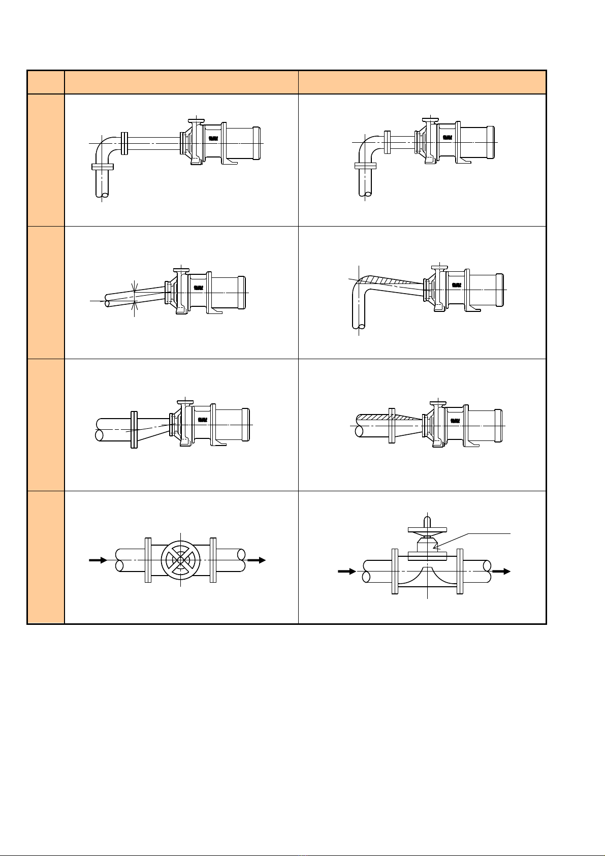
Fig. 4-4
Good Bad
Bend
Gradient piping
Piping with a reducer
Direction of gate valve
installation
L < 4D
Entrapped air
Entrapped air
L
≥
4D
Entrapped air
D: Pipe diameter
1/50

5. Notes on handling
5.1. Notes on the start-up
(1) Remove the external fan cover of the motor and confirm
that the external fan can be turned easily.
(2) Clean the supply tank and suction pipes as trash and/or
scales that have entered the suction pipes during the pipe
installation can cause a fatal damage.
(3) Confirm the rotational direction of the motor. (The direction
is indicated on the casing cover and the motor.)
Caution
If the bearing material is SiC, confirm the rotational direction
either after the priming or after removing the motor. Even an
instantaneous operation can cause damage.
(4) Completely open the valve on the suction piping.
(5) Perform priming to fill the pump with the fluid completely.
Discharge air using the discharge piping, etc. to perform
priming. If it is difficult to discharge air, turn the external fan
of the motor in the reverse direction manually three to four
times.
(6) Start the pump with the discharge valve completely closed.
(7) If the pump is fully primed, the discharge pressure will rise
immediately. Then open the discharge valve slowly and set
the operational pressure or discharge rate at a desired
level.
Caution
Possible Explosion
Pay extra attention to the priming operation because a
no-load operation or an operation with insufficient priming
can cause a fatal fault. In addition, note that there is a
possibility of explosion due to a rise in temperature in an
explosive atmosphere.
If the discharge pressure drops, stop the pump and find the
cause of insufficient priming.
Possible Explosion
A prolonged no-discharge operation will lead to a rise in
fluid temperature ultimately causing a danger of explosion.
Ensure to open the discharge valve as soon as possible.
Although the preferred time depends on the conditions of
the fluid and facility, it is recommended to open the valve
within one minute as a guideline. (SS-EN 13463-1)
i
Information
Sometimes, one priming operation is not sufficient to secure
enough initial fluid volume. Either repeat inching operation
and priming several times or release air from the suction
piping to amass sufficient initial fluid volume.
5.2. Notes on the operation
(1) Checking the sound
Sucking in air or objects from the suction pipe often cause
an abnormal sound with a vibration. A fluctuation of the
needle on the suction gauge is often caused by infiltration of
air.
(2) Inspection of vibration
A precaution is necessary for cavitation or vibration due to
faulty installation. Always adjust the discharge rate using
the discharge valve. Do not close the valve on the suction
piping.
(3) Others
Pay attention to the discharge pressure, suction, flow rate,
electric current value, etc. An abnormal fluctuation and/or a
drop in these values often is a result of a solid matter being
stuck or air being sucked in on the suction side.
Possible Explosion
In a self-priming pump, the fluid will be agitated by the
self-priming operation. Check the possibility of explosion if
the fluid is a flammable one listed in Dangerous Goods
Ordinance, Article 4 Dangerousness Characteristics.
Possible Explosion
Since the portion of the pump interfacing with the fluid is
made of a plastic material, the portion may become
electrically charged if it is used with a highly insulating fluid.
5.3. Notes on stopping
(1) Normally, the pump should be stopped after completely
closing the discharge valve. Closing the suction valve first
will cause cavitation and may result in a seizure.
(2) If the pump is run with the fluid forced in, close the suction
valve after stopping the pump.
(3) If the pump stops as a result of a power outage during an
operation, first turn off the power switch and, at the same
time, close the discharge valve manually.
5.4. Notes operational interruption
If the operation is interrupted for a prolonged period, drain the
pump. This is especially important in winter, when the fluid inside
the pump could freeze and the resulting expansion in the volume
could cause a crack or breakage of the piping.
5.5. Notes on the motor
(1) For the purpose of the operation in areas with a risk of
explosion, the maximum allowable temperature of the pump
fluid also depends on the motor like the pump's temperature
classification. In case of a flange motor, prohibit running the
motor exceeding the maximum allowable temperature
specified by the supplier for the shaft and the flange.
(2) The outer magnet is set on the motor shaft. In case of
disassembling/assembling, ensure to tighten the fastening
bolts for the motor shaft and outer magnet at our specified
standard torque. [Refer to 22.4 Tightening Torque for the
Outer Magnet Fastening Screws.]
Possible Explosion
If the motor is not set properly on the bracket or the outer
magnet is not secured properly with the fastening bolts,
there is a possibility that sparks will be generated during the
operation due to contacts between the outer magnet and
the bracket. (SS-EN 13463-5)
[Refer to 22.3. Gap between the Bracket and Outer
Magnet.]
5.6. Notes on the ambient temperature
The allowable ambient temperature range is from −10°C to 40°C.
(However, use the product under the normal room temperature
whenever possible.)
The symbol "X" is indicated on the pump label as the allowable
ambient temperature in compliance with EC Directive 94/9/EG.
(Refer to Chapter 22.)
5.7. Notes on the fluid
(1) Pay attention not to let bubbles being formed in the fluid.
(2) Ensure to keep the slurry density below 5% and the particle
diameter below 200 μm.
* The above conditions may differ depending on the type of
fluid and operational conditions. Use them as a reference.
5.8. Others
(1) Run the auxiliary pump attached to the piping once in a
while to confirm its readiness for operation.
(2) A no-load operation of the pump will cause a seizure of the
bearing and may result in a fatal accident and, thus, should
be avoided at all times.
(3) Use the pump at a designated discharge rate and water
head. Do not attempt to run it at an extremely high or low
discharge rate.
5.9. Ordering spare parts
For ordering spare parts, confirm the construction and the parts
name and inform them together with the type, parts name and
serial number to the supplier or Seikow Chemical Engineering &
Machinery. Note that the label is on the side of bracket.

6. MER type
6.
1
.
C
onstruction and parts name
No. Parts name Material Q’ty Remarks
No. Parts name Material Q’ty Remarks
001 Casing PVDF / ETFE 1
059 Magnet lining PVDF 1
002 Casing cover FC200 1
060 Rear casing C-PVDF 1 C-ETFE
013 Impeller PVDF / ETFE 1
096 Bracket ring SS400 1
018 Main shaft Al
2
O
3
/ SiC 1
102-01 O-ring (casing) FPM / EPDM 1 G-190
028 Bracket FC200 1
102-12 O-ring (drain plug) FPM / EPDM 1 P-9
038 Drain plug PVDF / ETFE 1
104-03 Casing bolt SUS304 6
051 Front bearing C/G-PTFE 1 Carbon/SiC
104-23 Motor bolt SUS304 4
052 Rear bearing C/G-PTFE 1 Carbon/SiC
104-31 Suction pipe cover bolt SUS304 6
053 Suction pipe cover FC200 1
104-42 Discharge pipe cover bolt SUS304 3
054 Front thrust Al
2
O
3
/ SiC 1
104-46 Outer magnet fastening screw
SNCM 2
055 Discharge pipe cover FC200 1
104-54 Rear casing bolt SUS304 2
056 Rear thrust Al
2
O
3
/ SiC 1
901 Motor 1
057 Outer magnet Rare earth 1
912 Adaptor ring SS400 1
058 Inner magnet Rare earth 1
(902) (Motor liner) SS400 1 *1
*1: When installing a 2.2kW-eG3/3.7kW general purpose motor, mount the 902 motor liner instead of an adaptor ring.

6.2. Maintenance and inspection
6.2.1. Routine inspection
Perform the following inspection and record the results.
(1) The fluid level of the supply tank
(2) The suction and discharge pressure
(3) The current of the motor and the bearing temperature
(4) Abnormal noise and abnormal vibration
(5) Leaks on flanges and O-ring
6.2.2. Regular inspection
Be careful in handling metals not to squeeze hands or finegers
since the outer and inner magnets are very strong (magnetic
force).
Also, be extra careful in handling the main shaft, bearings, and
thrust rings as they have the potential of break and may cause
serious injuries.
6.2.3. Abrasive limit of the bearing
A [mm] φB [mm] C [mm]
At the time of
delivery 6.0 20.5 5.0
At the time of
replacement 5.0 21.5 4.0
Fig. 6-1
A
φ
B
C
Front bearing Rear bearing
Components Inspection item Action/replacement timing
Casing
Accretion on the interface with the fluid Washing
Corrosion and swelling on the O-ring Replace if faulty
Presence of cracks Check the cause if present
Presence of wears, rubbing, or cracks on the front thrust Check the cause if present
Impellers
Accretion on the blades, presence of foreign matters Washing
Contact of entrance Check the cause if present
Inner magnet
Rubbing against the rear casing Check the cause if present
Presence of cracks on the edge and cylinder inner surfaces Check the cause if present
Accretion on the interface with the fluid Washing
Wear on the front bearing Check the cause if abnormal
Clogged cooling path on the front bearing Washing
Wear on the rear bearing Check the cause if abnormal
Rear casing
Rubbing against the inner magnet Check the cause if present
Accretion on the interface with the fluid Washing
Presence of wears, rubbing, or cracks on the rear thrust Check the cause if present
Main shaft
Presence of cracks Check the cause if present
Wear on the bearing Check the cause if abnormal
Outer magnet
Rubbing against the rear casing Check the cause if present
Connection condition of the outer yoke and the motor shaft, loose
screws
Redo tightening at the
proper position
Motor bearing Presence of abnormal noise Once in two years
(guideline)

6.3. Disassembling & assembling
6.3.1. Notes on disassembling
(1) Wear appropriate protective gear (rubber gloves, protective
goggles) before disassembling the pump.
Warning
There is a danger of injury resulting from the human body
getting in contact with the chemical during or after the
disassembling operation.
(2) Be careful in handling the main shaft and bearings as they
are vulnerable to physical damage.
(3) Since the inner and outer magnets are strongly magnetized,
pay attention to attraction of metallic dusts and metallic
items.
Warning
If a finger gets caught in between the inner or outer magnet
and a metal when they attract each other, a serious injury
can be expected.
6.3.2. Preparation for disassembling
(1) Ensure the safety of operation, for example securing the
footing.
(2) Turn OFF the main power to prevent an accidental operation
of the motor and indicate a maintenance work is in progress
with a sign so that nobody would turn on the power.
Warning
Possible Explosion
The worker may suffer a serious injury if the power is turned
on inadvertently during a disassembly operation. In
addition, it may cause an explosion in an explosive
atmosphere.
(3) Close the valves on the suction/discharge piping completely
and indicate that a maintenance work is in progress with a
sign so that nobody would release the valves.
(4) Before loosening flange bolts, wear a pair of rubber gloves,
protective goggles, etc. and drain the pump and piping from
the drain provided on the pump.
Warning
If the chemical splashes outside the pump and attaches to
the human body, it may results in a burn or a serious injury.
(5) As for the procedures for draining, refer to the common
example explained below and give a thorough
consideration to the fluid and working environment involved.
1) Release the pump drain.
2) Loosen the bolts on the discharge side drain connection
slowly and evenly. If the fluid leaks from the drain during
this operation, wait for the fluid to stop and retreat to a
safe position until the fluid comes to a complete stop.
Warning
(1) If the bolts on the pump flange on the discharge side
were loosened quickly, the fluid may scatter from the
drain and cause a serious injury to the worker.
(2) It is dangerous to stand in front of the drain during the
draining operation. Always check the standing position
while proceeding with the operation.
(6) Repeat the step 2) described above and confirm that the
drain operation is complete by lifting the piping with a
screwdriver or a similar tool when the bolts are removed.
6.3.3. Disassembling
(1) Remove the casing bolts (104-03), pull the casing cover
(002) and casing (001) towards the front and detach them
from the bracket (028). In doing this, the rear casing (060)
will be drawn out at the same time.
Photo 6-1
Photo 6-2

(2) Put down the pump with the suction flange facing down.
Photo 6-3
(3) Remove the rear casing bolts (104-54) and remove the rear
casing (060).
Photo 6-4
(4) Draw out the inner magnet (058+059) and the impeller
(013).
Photo 6-5
Photo 6-6
6.3.4. Assembling
For assembling the pump, follow the disassembling procedure in
reverse order.
(1) With the suction flange facing down, set the casing O-ring
(102-01) on the casing (001).
(2) Insert the inner magnet (058+059) and the impeller (013)
from above.
(3) Fit in the rear casing (060) from above, set the rear casing
bolts (104-54) and tighten them.
(Hold the tightening torque to the level of manual
tightening.)
(4) Hold the casing over (002), set it on the bracket (028), and
tighten the casing bolts (104-03) with a tightening torque of
21.5 N/m (2.2 kgf/m). In doing so, tighten the bolts in
diagonal order to avoid uneven clamping.
Warning
Since the inner and outer magnets attract each other, be
careful to avoid fingers being caught.
(5) Upon completion of assembling, remove the external fan
cover of the motor and confirm that the external fan can be
turned easily by hand.
6.3.5. Replacement of the motor and outer magnet
(1) Suspend the motor with a nylon sling, remove the motor
bolts (104-23), draw out the motor and outer magnet from
the bracket, and put down the motor with the external fan
facing down.
(2) Loosen the outer magnet fastening screws (104-46) and
draw out the outer magnet (057) from the main shaft of the
motor.
(3) To install, insert the outer magnet (057) into the main shaft
of the motor and tighten the outer magnet fastening screws
(104-46) observing the torque specified in 22.4 Tightening
Torque for the Outer Magnet Fastening Screws. In doing so,
align the bottom of outer magnet and the top of the motor
shaft. (Fig. 6-2)
Fig. 6-2
Motor shaft
Outer magnet
Same
surface

0.5mm以下
主軸
フロントスラスト
ケーシング
主軸挿入部
6.3.6. Replacement of the main shaft and front
thrust
(1) To remove, put a Phillips driver through the hole on the
casing support and tap on the driver head lightly with a
hammer with the tip in contact with the main shaft.
Photo 6-7
(2) To install, align the cuts on the main shaft (018), the front
thrust (054) and the shaft support portion of the casing
(001) and then tap on the rear end of the main shaft with a
plastic hammer until they are firmly in place.
Photo 6-8
Fig. 6-3
6.3.7. Replacement of the front bearing
(1) To remove, hold a round rod (24mm diameter) against the
bearing from the back of inner magnet (058+059) (from the
rear bearing (052) side) and tap on it with a plastic hammer.
Photo 6-9
(2) To install, align the cuts from the impeller side and press fit
the front bearing by tapping it lightly with a plastic hammer
by covering the rubbing surface with the front thrust (054)
with a cloth to avoid damaging the surface.
Photo 6-10
6.3.8. Replacement of the rear bearing and the rear
thrust
(1) To remove, lift the rear thrust with a sharp edge, such as an
edge of a cutting knife, after melting the melting teeth with a
hot-air welder.
Photo 6-11
(2) To install, align the cuts, melt the melting teeth at two
locations with a hot-air welder, and then crush them with a
round rod (4mm diameter).
0.5 mm or less
Inserted portion of
the casing main
shaft Front thrust
Main shaft

6.3.9. Replacement of the casing and casing cover
(1) Remove the discharge pipe cover bolts (104-42) and
remove the discharge pipe cover (055).
Photo 6-12
(2) Remove the suction pipe cover bolts (104-42) and remove
the suction pipe cover (053). Although the top cover can be
drawn out directly, remove the bottom cover by turning it so
that it won't hit the drain. If it is difficult to pull it apart due to
rust and/or stains, tap on it lightly with a plastic hammer.
Photo 6-13
(3) Remove the casing (001) from the casing cover (002) by
pushing the surface of the suction flange with a hand or by
tapping it lightly with a plastic hammer.
Photo 6-14
(4) To install, set the casing on the casing cover and hammer it
in lightly with a plastic hammer.
(5) Next, attach the bottom part of the suction pipe cover. In
doing this, insert the cover from the side avoiding the cover
hitting the drain. If the insertion is difficult, tap on it lightly
with a plastic hammer.
(6) Set the suction pipe cover bolts and tighten them.
(7) Set the discharge pipe cover bolts and tighten them.

7. MEH-040 type
7.
1
.
C
onstruction and parts name
No. Parts name Material Q’ty Remarks
No. Parts name Material Q’ty Remarks
001 Casing PVDF / ETFE 1
060 Rear casing C-PVDF 1 C-ETFE
002 Casing cover FC200 1
096 Bracket ring SS400 1
013 Impeller PVDF / ETFE 1
102-01 O-ring (casing) FPM / EPDM 1 G-190
018 Main shaft Al
2
O
3
/ SiC 1
102-12 O-ring (drain plug) FPM / EPDM 1 P-9
028 Bracket FC200 1
104-03 Casing bolt SUS304 6
038 Drain plug PVDF / ETFE 1
104-23 Motor bolt SUS304 4
051 Bearing C/G-PTFE 1 Carbon/SiC
104-31 Suction pipe cover bolt SUS304 6
053 Suction pipe cover FC200 1
104-42 Discharge pipe cover bolt SUS304 3
054 Front thrust Al
2
O
3
/ SiC 1
104-46 Outer magnet fastening screw
SNCM 2
055 Discharge pipe cover FC200 1
104-54 Rear casing bolt SUS304 2
056 Rear thrust Al
2
O
3
/ SiC 1
105 Mouth ring C/G-PTFE 1 Carbon/SiC
057 Outer magnet Rare earth 1
901 Motor 1
058 Inner magnet Rare earth 1
912 Adaptor ring SS400 1
059 Magnet lining PVDF 1
(902) (Motor liner) SS400 1 *1
*1: When installing a 2.2kW-eG3/3.7kW general purpose motor, mount the 902 motor liner instead of an adaptor ring.

7.2. Maintenance and inspection
In order to operate the pump in an orderly manner, it is
recommended to implement a regular inspection program and
keep the record. Shown below are common points of
maintenance.
7.2.1. Routine inspection
Perform the following inspection and record the results.
(1) The fluid level of the supply tank
(2) The suction and discharge pressure
(3) The current of the motor and the bearing temperature
(4) Abnormal noise and abnormal vibration
(5) Leaks on flanges and O-ring
7.2.2. Regular inspection
Be careful in handling metals not to squeeze hands or fingers
since the outer and inner magnets are very strong (magnetic
force).
Also, be extra careful in handling the main shaft, bearings, and
thrust rings as they have the potential of break and may cause
serious injuries.
7.2.3. Abrasive limit of the bearing
A [mm] B [mm] φC [mm]
At the time of
delivery 8.0 5.0 20.5
At the time of
replacement 7.0 4.0 21.5
Fig. 7-1
Mouth ring Bearing
Components Inspection item Action/replacement timing
Casing
Accretion on the interface with the fluid Washing
Corrosion and swelling on the O-ring Replace if faulty
Presence of cracks Check the cause if present
Presence of wears, rubbing, or cracks on the front thrust Check the cause if present
Impellers
Accretion on the blades, presence of foreign matters Washing
Contact of entrance Check the cause if present
Wear on the mouth ring Check the cause if present
Inner magnet
Rubbing against the rear casing Check the cause if present
Presence of cracks on the edge and cylinder inner surfaces Check the cause if present
Accretion on the interface with the fluid Washing
Wear on the bearing Check the cause if abnormal
Clogged cooling path on the bearing Washing
Rear casing
Rubbing against the inner magnet Check the cause if present
Accretion on the interface with the fluid Washing
Presence of wears, rubbing, or cracks on the rear thrust Check the cause if present
Main shaft
Presence of cracks Check the cause if present
Wear on the bearing Check the cause if abnormal
Outer magnet
Rubbing against the rear casing Check the cause if present
Connection condition of the outer yoke and the motor shaft, loose
screws
Redo tightening at the
proper position
Motor bearing Presence of abnormal noise Once in two years
(guideline)
This manual suits for next models
9
Table of contents
Other TEXEL Water Pump manuals

Popular Water Pump manuals by other brands

Zoeller
Zoeller 1461-0006 manual

AST
AST SOC GMP-050 Series instruction manual

Bestway
Bestway Built-in Sidewinder P3150 owner's manual

Homa
Homa Saniboy G 180-16W Original instruction manual

Gardena
Gardena PTU 3700/4 Operator's manual

GORMAN-RUPP
GORMAN-RUPP 02F1-GL Application, Installation, Operation, and Maintenance Manual

Ebsray
Ebsray RC SERIES Installation, operation & maintenance instructions

IWAKI AMERICA
IWAKI AMERICA MD SERIES instruction manual

Advantage Controls
Advantage Controls MicroTron O Series manual

Waspper
Waspper WP20CH/P instruction manual

Kremlin-Rexson
Kremlin-Rexson AIRMIX 08-120 Disassembly/Reassembly

Nakayama
Nakayama PRO NP1070 manual


