SoliTherm LT 58100-120V User manual

Version Nr. 1-1 - 10.01.2018 Doc. Nr. 99581001001 1 / 10
Table of Content LT 58100-120V
1. User manual 2 ...................................................................................................................
2. Legal regulations 2 ...........................................................................................................
3. Safety instructions 3 ........................................................................................................
4. Technical information 4 ...................................................................................................
5. Functional principle 4 ......................................................................................................
6. Technical data 5 ................................................................................................................
7. Mounting 6 .........................................................................................................................
8. Electrical connection 7 .....................................................................................................
9. Wiring diagram 7 ..............................................................................................................
10. Taking into operation 9 .................................................................................................
11. Trouble shooting 9 ........................................................................................................
12. Maintenance & Cleaning 9 ............................................................................................
13. Transport & Storage 10 .................................................................................................
14. Parts supplied 10 ............................................................................................................

Version Nr. 1-1 - 10.01.2018 Doc. Nr. 99581001001 2 / 10
1. User manual
This instruction manual contains information and instructions to enable the user to work safely,
correctly and economically on the unit. Understanding and adhering to the manual can help one:
Avoid any dangers.
●
Reduce repair costs and stoppages.
●
Extend and improve the reliability and working life of the unit.
●
PLEASE ENSURE TO USE THE RIGHT VERSION OF THE INSTRUCTION MANUAL SUITABLE FOR
YOUR UNIT.
Conditions of use
The unit is to be used exclusively for the dissipation of heat from control cabinets and enclosures in
order to protect temperature sensitive components in an industrial enviorment. To meet the conditions
of use, all the information and instructions in the instruction manual must be adhered to.
General danger
Indicates compulsory safety regulations which are not
covered by a specific pictogram such as one of the following.
High electric voltage
Indicates electric shock danger.
Important safety instruction
Indicates instructions for safe maintenance and operation of
the unit.
Attention
Indicates possible burns from hot components.
Attention
Indicates possible damage to the unit.
Instruction
Indicates possible danger to the environment.
2. Legal regulations
Liability
The information, data and instructions contained in this instruction manual are current at the time of
going to press. We reserve the right to make technical changes to the unit in the course of its
development. Therefore, no claims can be accepted for previously delivered units based on the
information, diagrams or descriptions contained in this manual. No liability can be accepted for
damage and production caused by:

Version Nr. 1-1 - 10.01.2018 Doc. Nr. 99581001001 3 / 10
Disregarding the instruction manual
●
Operating error
●
Inappropriate work on or with the unit
●
The use of non-specified spare parts and accessories
●
Unauthorised modifications or changes to the unit by the user or his personnel
●
The supplier is only liable for errors and omissions as outlined in the guarantee conditions contained in
the main contractual agreement. Claims for damages on any grounds are excluded.
3. Safety instructions
Upon delivery the unit is already meeting current technical standards therefore it can be safely taken
into operation. Only trained specialists are allowed to work on the unit. Unauthorised personnel must
be prohibited from working on the unit. Operating personnel must inform their superiors immediately if
any malfunction of the unit becomes apparent.
Please note that before starting to work on or with the unit, a procedure must be carried out inside the
cabinet on which the unit is to be mounted.
Before commencing work inside the cabinet, the control cabinet manufacturer's instruction must be
read with regards to:
Safety instructions.
●
Instructions on taking the cabinet out of operation.
●
Instructions on the prevention of unauthorised cabinet reconnection.
●
The electric equipment meets the valid safety regulations. One can find dangerous voltage (above 50V
AC or above 100V DC)
Behind the control cabinet doors.
●
On the power supply in the unit housing.
●
The unit has to be fused according to the type plate and the wiring diagram, and must be protected
externally from overloading and electrical faults via suitable protective devices such as ground fault
protection breakers.
Danger through incorrect work on the unit
The unit can only be installed and maintained by technical competent and
qualified personnel, using only supplied material according to the supplied
instructions.
Danger from electrical voltage
Only specialised personnel are allowed to maintain and clean the unit. The
personnel must ensure that for the duration of the maintenance and cleaning, the
unit is disconnected from the electrical supply.
Attention
Damage to the unit through the use of inappropriate cleaning materials. Please do
not use aggressive cleaning material.
Instruction
Damage to the environment through unauthorised disposal. All spare parts and
associated material must be disposed according to the environmental laws.

Version Nr. 1-1 - 10.01.2018 Doc. Nr. 99581001001 4 / 10
4. Technical information
Air-air heat exchangers are intended as complementary accessories to large industrial equipment
which include a motor-operated fan or blower together with a heat exchanger module. These may also
include an electric heater. The fan or blower is intended to recirculate air and allow heat exchange.
The heat exchanger is designed for air heat transfer only.
Cooling function may be controlled by an on-board or remote controller or thermostat. Heating
function, when installed is provided by an electrical heating element. The unit seals the cabinet which
ensures that the clean air inside does not come into contact with the ambient air which may well be
dirty or polluted. The unit is fit for purpose within the rated/declared ambient conditions (e.g. dusty
and oily air or high air temperatures between 23°F and 131°F), also indicating the rated allowable
ingress and environment.
Heat exchangers are used where the heat generated by energy losses in control cabinets must be
conducted away to protect temperature-sensitive components. The characteristic graph shown in the
section “Performance graph” applies to external (ambient) air as the coolant.
In air-to-air heat exchangers, the internal temperature of the control cabinet cannot be cooler than the
ambient temperature. There are natural limits to the cooling performance, dependent on the air supply
temperature and the requirement for a temperature difference of at least 9°F. Unlike systems in which
the heat generated is allowed to escape by air convection through ventilation slots, with the heat
exchanger, the clean air inside the control cabinet is prevented from mixing with the air outside, which
may well be unclean.
5. Functional principle
Functional principle
The heat exchanger is a cooling device that creates a heat-transfer through a large area of thin
aluminium sheet metal folded up in the heat exchanger core by means of forced convection. Used
within an enclosure, it uses the ambient air as cooling medium, thus avoiding the utilisation of
refrigerant.
The cooling performance of the heat exchanger is dependant on the ambient (external) air
temperature. The internal fan is set to be always on. The external fan is controlled via a thermostat.
When the cabinet temperature increases beyond the pre-set thermostat temperature, the external fan
is switched on and the heat exchanger starts cooling. Cooling stops when the cabinet temperature
cools below the pre-set temperature. Switching difference is of 12.6˚F (+/-7.2˚F).

Version Nr. 1-1 - 10.01.2018 Doc. Nr. 99581001001 5 / 10
6. Technical data
Order Number 581001001
Heat exchanger performance 55 W/°F
Temperature range -40°F - 149°F
Mounting External
Housing Material Mild steel, powder coated
Dimension HxWxD 36 x 18.x 8.6 inch
Weight 77 lbs.
Voltage / Frequency 120 V ~ 60 Hz
Rated current 1.8 A / 2.4 A
Max. power 280 W
Fuse 4 A (T)
Connection Connecting cable 6 ft.
NEMA Type NEMA type 12, 3, 3R, 4
Approvals CE, RoHS

Version Nr. 1-1 - 10.01.2018 Doc. Nr. 99581001001 6 / 10
7. Mounting
Danger from electrical voltage
The unit must be mounted by specialist personnel (qualified
electricians). The personnel must ensure that the cabinet is
disconnected from the electrical supply for the duration of the
mounting operation. Therefore take the cabinet out of operation,
following the relevant instructions before mounting work commences.
Danger through incorrect work on the unit. Only specialists are allowed
to put the unit into operation.
Mounting preparations
Several points must be checked before the unit can be mounted. These checks must be made to
ensure safety and the trouble-free operation of the unit. These checks must be carried out with
absolute thoroughness to ensure that the unit works perfectly.
Transport damage check
On delivery the carton containing the unit must be examined for signs of transport damage. Any
transport damage to the carton could indicate that the unit itself has been damaged in transit which in
the worst case could mean that the unit will not function.
Location and space requirements
The location of the cabinet must allow for sufficient air circulation to and from the unit. The unit should
be mounted roughly horizontally. It is therefore advisable to check that the cabinet is in a horizontal
position. The max. deviation from the vertical or horizontal should not excess 20 degrees.
Sealing
To guarantee that the unit works perfectly ensure that, the control cabinet is completely sealed (min.
NEMA 12) and a good seal exists between the control cabinet and the unit. If necessary the cabinet
mounting surface should be reinforced.

Version Nr. 1-1 - 10.01.2018 Doc. Nr. 99581001001 7 / 10
8. Electrical connection
The cooling unit is used where heat needs to be dissipated from electrical control cabinets or similar
enclosures in order to protect heat sensitive components. The unit has two completely separate air
circuits which ensure that the clean cabinet air does not come into contact with the ambient air which
may well be dirty or polluted. Control cabinet air conditioners can dissipate large quantities of heat
from sealed enclosures such as control cabinets into the ambient air and at the same time reduce the
cabinet internal temperature to below that of the ambient air.
The control cabinet air conditioner can function without problems in extreme ambient conditions (e.g.
dusty and oily air) with an standard operating temperature ranging between -4°F and 131°F. The
stated cooling capacities are according to DIN 3168.
Controller
The unit is equipped with a temperature controller which regulates the function of the refrigeration
cycle. On normal working conditions the display shows the temperature inside the enclosure. The
controller “set point” for the interior of the enclosure (parameter St / St1) is pre-set at 95°F and can be
adjusted between 68°F and 122°F.
The High temperature alarm (parameter AH) is preset at 131°F. The High Temperature Alarm relay is
delivered as “normally closed” (H1=1). If you need to change it to “normally open”, please modify
value of parameter H1 (H1=2).
Modifying controller parameters
1. Press the SET button for more than 3 sec. (if there are active alarms, mute the buzzer).The display
shows the parameter code ‘PS’ (password).
2. Only for parameters requiring password: Press the SET button to access the password setting, use
the UP and DOWN buttons to scroll the numbers until displaying, “22” (default password to access the
parameters), press the SET button to confirm the password
3. Use the UP and DOWN buttons to scroll the parameters. The LED corresponding to the category of
parameters will be on
4. Press SET to display the value associated with the parameter
5. Increase or decrease the value using the UP or DOWN button respectively
6. Press SET to temporarily save the new value
7. Press the SET button for more than 3 sec. to permanently save the new parameters and exit the
parameter setting procedure.
If no button is pressed for 60 sec. all changes made to the parameters, temporarily saved in the RAM,
will be cancelled and the previous settings restored. The cooling unit manufacturer is in no way liable
for any alterations the customer may make to the factory set parameters, unless the manufacturer has
authorized the customer in writing to change them.
Door Switch
The unit can be switched on and of via a door contact switch. When delivered the door contact
terminals are bridged on the female connector. To connect the door contact switch remove the bridge
and connect door contact switch. The contact must be closed when the cabinet door is closed.
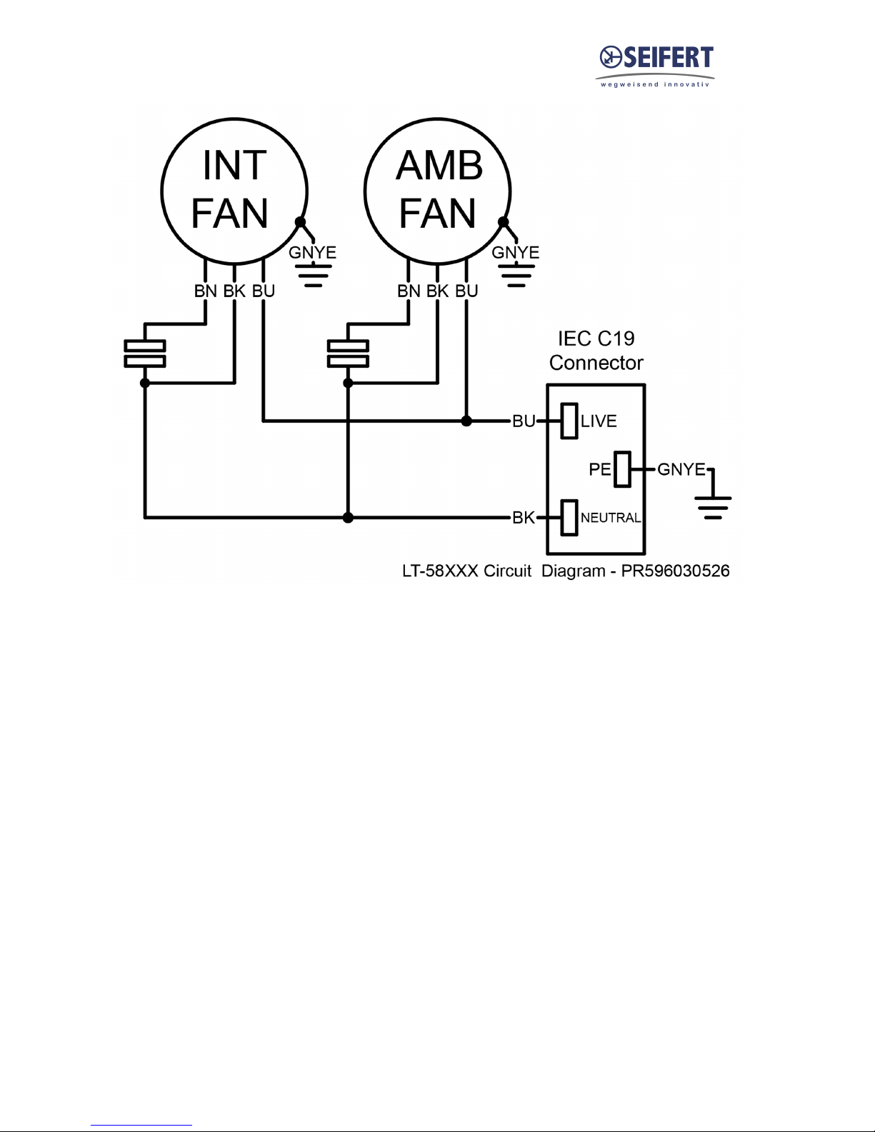
9. Wiring diagram
Version Nr. 1-1 - 10.01.2018 Doc. Nr. 99581001001 8 / 10

Version Nr. 1-1 - 10.01.2018 Doc. Nr. 99581001001 9 / 10
10. Taking into operation
As described in the chapter “Technical information”, the unit is controlled in relation to the cabinet
internal temperature. The required cabinet temperature can be set on the potentiometer on the
controller.The temperature adjustment range is between 32°F (left-hand stop) and 140°F (right-hand
stop). The thermostat is pre-set at 95°F.
To adjust the cabinet internal temperature proceed as follows:
Remove the MCB access plate on the front of the unit.
●
Using a screw driver turn the adjustment wheel on the potentiometer “TEMP” slightly to the right
●
(higher) or to the left (lower).
Please note that the setting for the alarm signal should be at least 41 - 50°F higher than the setting
●
for the cabinet internal temperature.
Check that the new adjustment meets the necessary requirements. If necessary, repeat the
procedure. Inspect and if necessary replace the MCB access plate sealing tape.
11. Trouble shooting
In case of a fault logon to our website www.saginawcontrol.com to locate your nearest servicing office
or find your nearest contact in the chapter “contacts” in this manual.
12. Maintenance & Cleaning
Danger from electrical voltage
Maintenance and cleaning must be carried out by specialists
(electricians). The personnel must ensure that for the duration of this
work the unit and the cabinet are disconnected from the electrical
supply and protected against unauthorised reactivation.
Danger through incorrect work on the unit.
The instructions in the cabinet manufacturer’s manual must be
adhered to!
Damage to the unit through incorrect maintenance and
repair! Maintenance and repair must be carried out by the
manufacturer or another specialist.
Fan replacement
The rated life expectancy of the fan is L10 =30,000 hours under normal operating conditions.
To replace the internal or external fan, please proceed as following:
Remove the internal access panel by unscrewing the 10 fixing screws.
●
Disconnect the blower cables from the connectors.
●
Unscrew the four screws fixing the blower bracket to the cabinet.
●
Unscrew the fan from the bracket.
●
Re-assembly with the new blower is in reverse order.
●
Make sure that the blower cable length is the same as the one of the removed fan to ensure that the
cable does not come in contact with the blower while in operation. Make sure that the correct polarity
is maintained. (Refer to circuit diagram). Inspect and if necessary replace the internal access panel
Version Nr. 1-1 - 10.01.2018 Doc. Nr. 99581001001 10 / 10
sealing tape.
In addition the unit should have regular functional tests (approx. every 2,000 hours depending on the
grade of ambient pollution).
13. Transport & Storage
Malfunction due to transport damage
On delivery the carton containing the unit must be examined for signs
of transport damage. Any transport damage to the carton could
indicate that the unit itself has been damaged in transit which in the
worst case could mean that the unit will not function.
Storage conditions
The unit can only be stored in locations which meet the following conditions:
Temperature range: 104°F to 158°F
Relative humidity (at 77°F): max. 95%
Returning the unit
Damage to the unit through incorrect transport.
To avoid transport damage the unit should be returned in the original
packing or in a packing case and must be strapped to a pallet!
If the unit cannot be returned in the original packing please ensure that:
A space of at least 30 mm. must be maintained at all points between the unit and the external
●
packing.
The unit must be firmly fixed in the packing.
●
The unit must be protected sufficiently by shock absorbing padding (hard foam corner pieces, strips
●
or cardboard corner pieces).
14. Parts supplied
1 x Heat exchanger
1 x Instruction manual
1 x EC Declaration
6 x Slotted Studs M6 * 25
6 x Washers A6,4 DIN125
6 x Lock nuts M6 DIN 985
1 x Tight tape
1 x Drain connector
1 x O-ring
Seifert Systems GmbH Seifert Systems Ltd. Seifert Systems AG Seifert Systems Inc. Seifert Systems Pty Ltd.
Haßlinghauser Str. 156 HF09/10 Wilerstrasse 16 75 Circuit Drive 105 Lewis Road
Hal-Far Industrial Estate North Kingstown Wantirna South
58285 Gevelsberg Birzebbuga, BBG 3000 4563 Gerlafingen RI 0285 3152 Victoria
Germany Malta Switzerland USA Australia
Tel. +49 (0) 2332 55124-0 Tel. +356 2220 7000 Tel. +41 (0) 32 675 35 51 Tel. +1 401-294-6960 Tel. +61 (3) 98 01 19 06
Fax +49 (0) 2332 5512429 Fax +356 2165 2009 Fax +41 (0) 32 675 44 76 Fax +1 401-294-6963 Fax. +61 (3) 98 87 08 45
Table of contents
Popular Heater manuals by other brands

Scarlett
Scarlett SC-2050 instruction manual

Polygroup
Polygroup SUMMER WAVES SHM-1004 owner's manual

EUROM
EUROM Golden 2000 Giant instruction manual

Frico
Frico IR3000 quick guide

Empire
Empire SR-10T-2 Installation instructions and owner's manual

radiance
radiance SC-Plus Installation & operation instructions


