Inelco Dania SSH 3.3kW User manual
08 - 2023 JD
System stationary heater
Stacjonarna nagrzewnica elektryczna
Dania SSH 3.3kW
Instruction manual / Instrukcja obsługi
PL
EN
2
EN
Electric System Stationary
Heater Dania SSH 3.3kW Product 88843067 TYPE 2210
Important: read the entire user manual before device us-
ing, repair or cleaning. Improper use may cause injuries,
burns, electric shock or re. The appliance is not intended
for use by persons (including children) with reduced physical, sen-
sory or mental capabilities, or lack of experience and knowledge,
unless they have been given supervision or instruction concerning
use of the appliance by a person responsible for their safety. Chil-
dren should be supervised to ensure that they do not play with the
appliance.
Keep these instructions in a safe place for future reference.
SAFETY WARNINGS!
Do not cover – danger of re!
The appliance has hot surfaces during operation!
Ensure that the area around the intake and the exhaust grille
is kept free from material which could obstruct or stop the air
ow through the appliance.
Do not place the heater where inammable materials may be
placed on or near the heater!
The appliance must not be covered either with clothes or sim-
ilar material since overheating of the appliance can result in a
re hazard.
Do not use this heater in the immediate surroundings of a
bath, a shower or a swimming pool!
Do not cover the heater, the heater must not be exposed to
excess dust and humidity!
Do not use the heater outdoors !
Do not place the heater immediately below a socket-outlet!
Use this heater xed to the wall by dedicated wall bracket.
Do not use this heater if it has been dropped!
Do not use if there are visible signs of damage to the heater!
The space heater must only be disassembled by the manufac-
turer or a qualied service engineer!
The power cable must only be connected or replaced by the
qualied specialist!
3
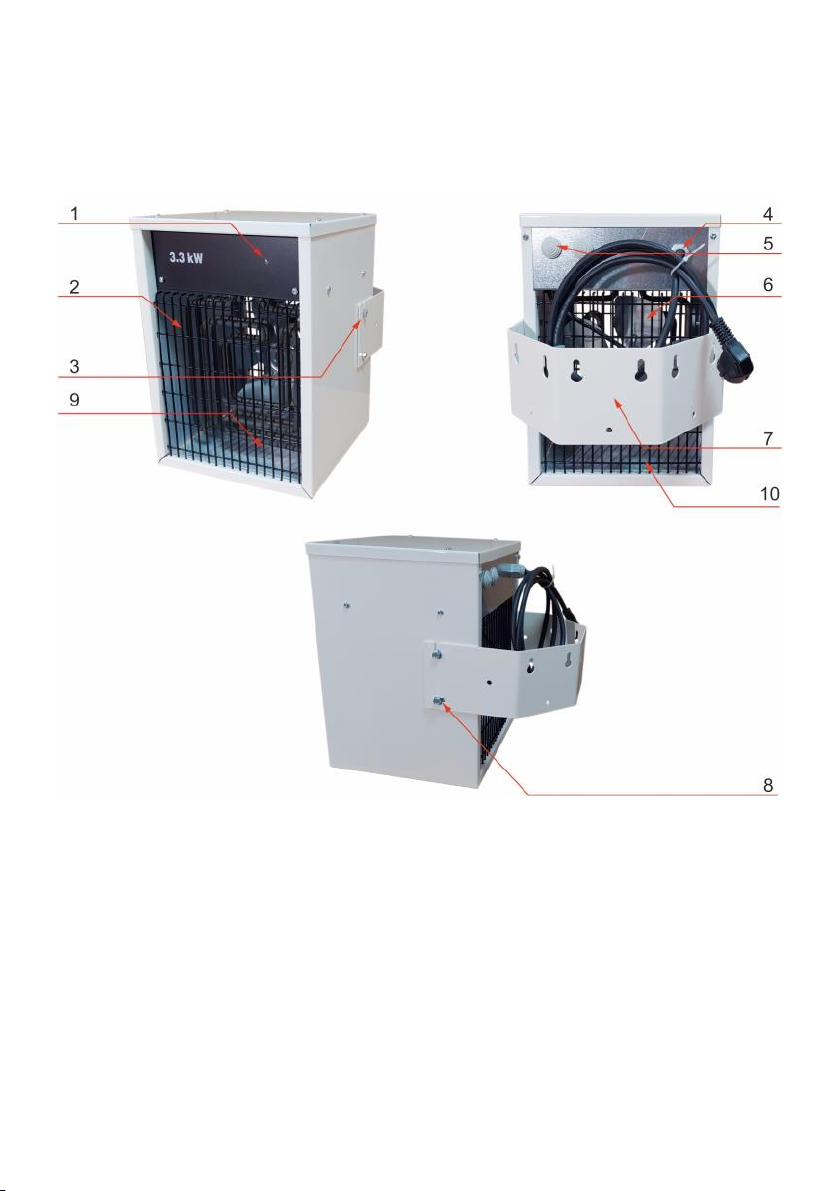
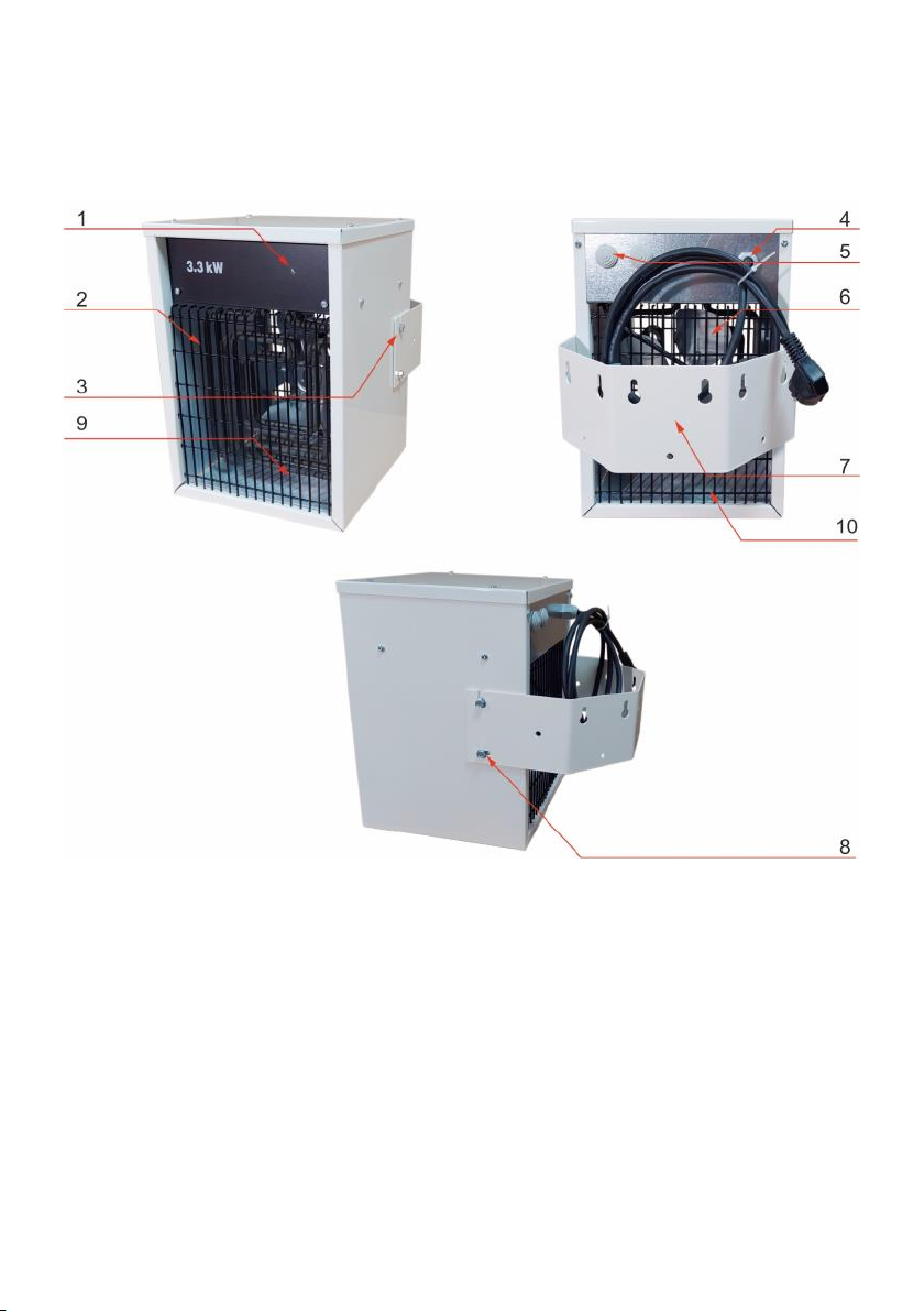
Figure 1. Unit elements description.
1. Control LED
2. Heating element
3. Wallmount xing screw
4. Power cable
5. Control cable entry dummy plug
6. Fan with electric motor
7. Wallmount bracket
8. Vertical air ow direction adjustment
9. Exhaust grille
10. Air intake

4
Purpose
The DANIA SSH electric stationary heaters are not intended for use
other than indoors. These heaters are suitable for the heating of ware-
houses, production halls, workshops, storage rooms, show rooms, gar-
ages etc.
Operation
The air is carried through the heater by a fan (gure 1 pos.6) and heat-
ed by heating elements (gure 1 pos.2) which are regulated by the ex-
ternal thermostat unit and Control Box . The air speed is non-
adjustable. There are two fan works regime available: fan works only
when thermostat is ON or fan works all the time -even when thermo-
stat is OFF. For details please refer to gure 5 or gure 6 appropriately .
Inelco recommend Salus 091FLV2 thermostat with programmer to be
used with DANIA SSH stationary heaters. For more details please refer
to gure 9.
IMPORTANT: the heater must be connected to the control
box and an external thermostat/ regulator. One control
box and one thermostat/regulator can control one heater
or a set of up to 6 heaters.
Switching on or off, selecting half or full output power or fan mode is
performed through the Control Box, which is wall mounted for easy
access. For details please refer to gure 10. Heaters is protected from
overheating via a built-in temperature limiter. To reset, see Overheat-
ing (page 12). Heater is mounted on a wall with a wallmount bracket,
which allows to obtain 3 various vertical and 3 various horizontal posi-
tions—please see gure 3 and gure 4.
Mechanical installation
The DANIA SSH 3.3kW stationary heater is intended for wall mounting.
The appliance must not be placed directly under a wall-outlet. The
minimum distances given in gure 2 must be kept. The heaters must
not be mounted on the ceiling.
1. Mark holes by means of the wallmount bracket.
2. Drill holes for the xing wall plugs.
5
4. Mount the fan heater on the bracket and adjust the heater to de-
sired vertical and horizontal position (refer to gures 3 and 4).
5. Screw the bottom bolt in and tighten all bolts.
Use wall fasteners appropriate for the wall material and weight of the
unit with a reasonable safety margin.
In order to ensure to the heater proper working conditions, the mini-
mum distances from the ceiling, walls located on the sides of the
heater and the minimum installation place height should be main-
tained.
The correct location of the heater installation will ensure effective
and uniform heating of the room, safety of use and will protect peo-
ple passing by from the possibility of collision with the heater.
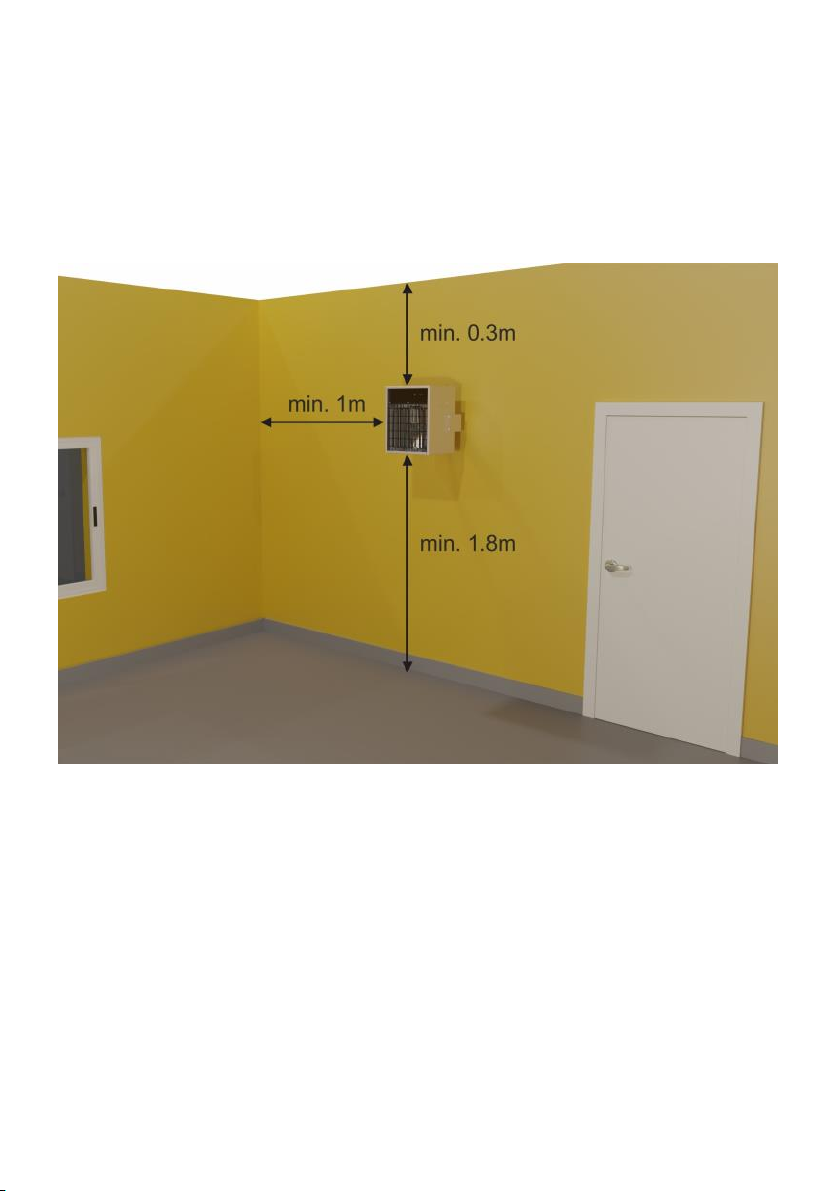
The recommended minimum distances are:
1. 0.3m from the ceiling
2. 1.0 m from the side walls
3. The minimum installation height from the oor is 1.8 m or higher
depending on the processes taking place near the heater.
Figure 2. Mounting on wall. Minimum distances.
6
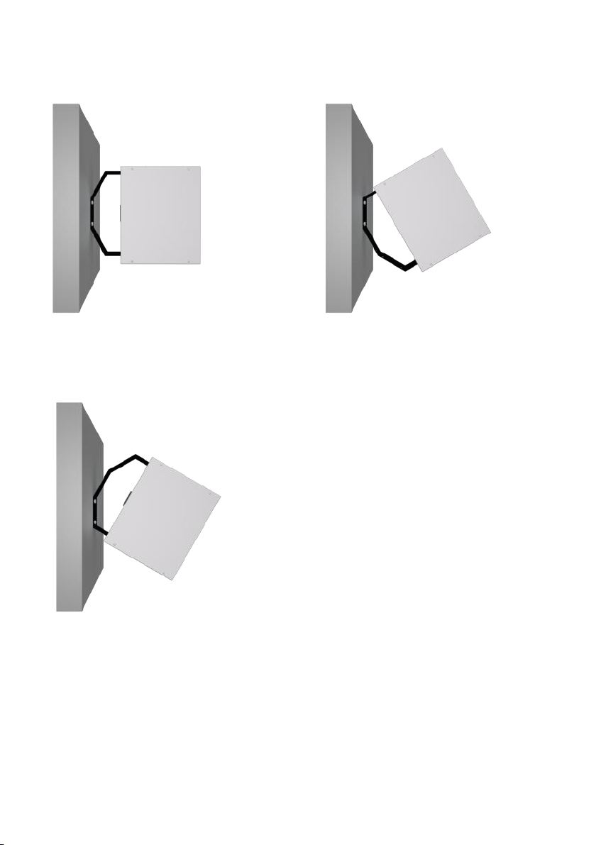
Figure 3. Mounting on the wall. Horizontal positions.
Pos.1 Pos.2
Pos.3
The wall bracket allows to obtain 3
various horizontal positions in rela-
tion to the mounting plane (wall):
pos.1 perpendicular to the wall
pos.2 tilted to the left
pos.3 tilted to the right
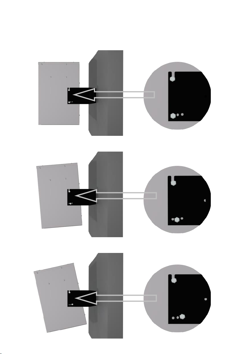
There are 3 positions of the heated air ow adjustment in the vertical
plane available:
1. horizontal airow (gure 4 pos. a)
2. slightly downward airow (Figure 4 pos. b)
3. slightly downward airow (Figure 4 pos. c).
To get right direction please choose one of mounting position available
in the wallmount bracket. For details please see gure 4.
7
Figure 4. Mounting on the wall. Vertical positions
A. Horizontal position
B. Slightly downward direction
C. Max downward direction

8
Electrical installation
The electrical installation should be carried out by a qualied electri-
cian in conformity with prevailing regulations.
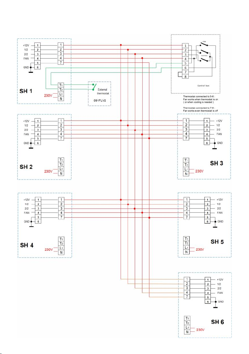
The heaters must be connected to 230V please refer to the schematic
gure 5 and gure 6.
Connection between the Control Box and DANIA SSH stationary heat-
er, should be made with a cable 0,75mm2 (or similar may be used).
The wire number should be in accordance to installation type chosen:
please refer to gure 5 and gure 6 accordingly.
On the back of the appliance there is a hole with entry dummy plug
(gure 1 pos. 5) to be used for the connection to the Control Box and
external thermostat.
Connections should be made in accordance with the attached dia-
grams:
1. Figure 5 if the installation consists only 1 heater
2. Figure 6 in case the installation consists of more than 1 heater
Figure 5. Wiring diagram for one heater installation
9
Figure 6. Wiring diagram for set of 2 up to 6 heaters
10
Figure 7. Heater power and steering connectors
To gain access to power cables connectors and control devices: con-
trol box and thermostat connectors, unscrew the screws securing
the cover of the heater housing and then remove the cover.
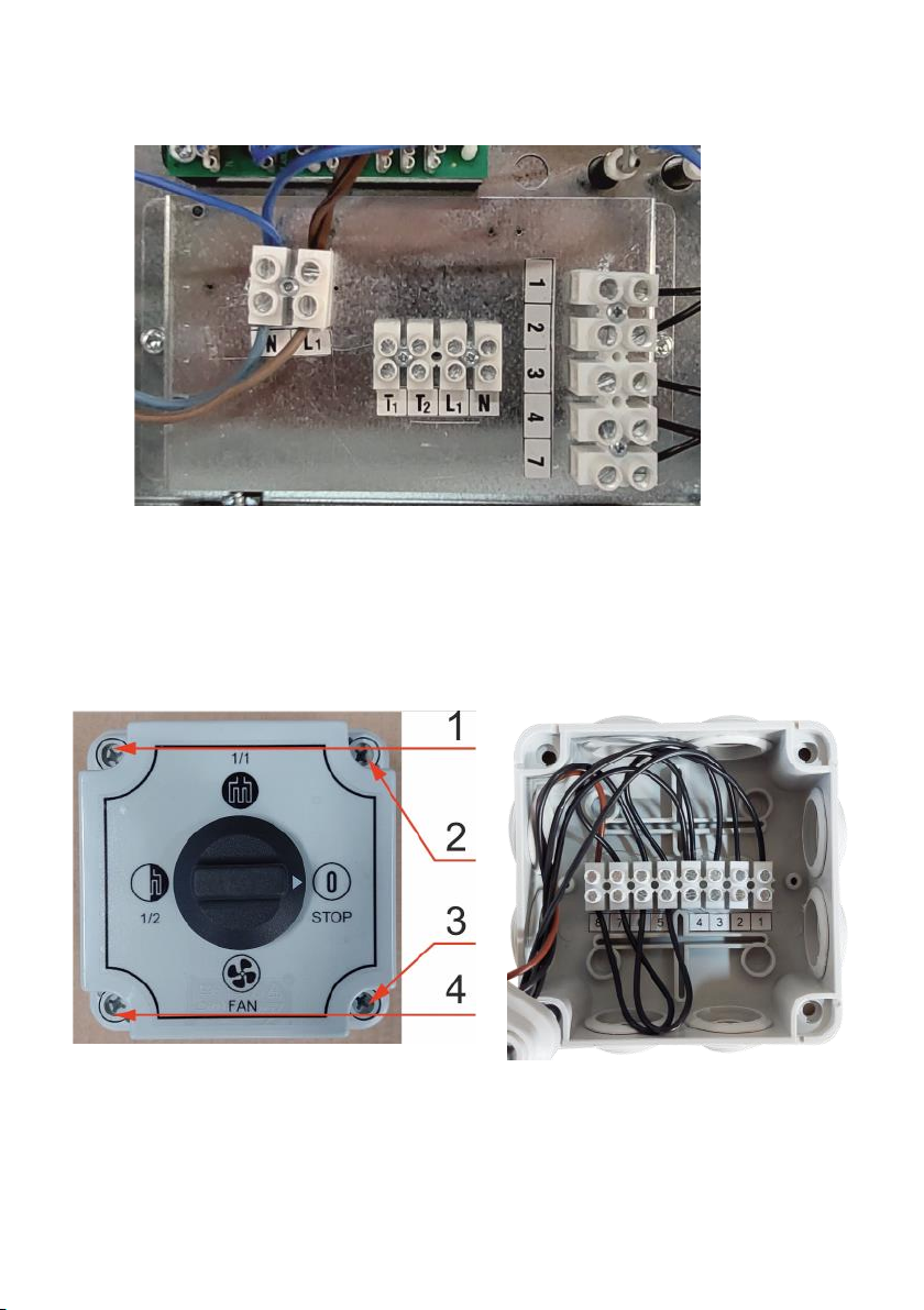
Figure 8. Control box connectors
To gain access to the control box connectors unscrew the screws
securing the cover (Fig. 8 p.1 ) and then remove the cover.
Fig. 8 p.1 Top cover screws location Fig. 8 p.2 Control box con-
nectors with wires.

11
Figure 9. Thermostat / wired programmer Salus 091FLV2
Inelco recommends SALUS 091FLV2 wired thermostat / programmer
to be used with stationary heaters Dania SSH series.
Thermostat manual instruction with wiring diagram is available at:
https://salus-controls.eu/
Important: use only thermostats with NO/COM voltage-free
relay on output. Using the product with a different solution
will damage the device.
Heater operation
First time use
While the manufacturing of the heaters, oil residues adhere to the
heating elements. The rst time of use, these residues will be burnt
off, thereby occasionally triggering re alarms. Appropriate precau-
tions should be taken in order to prevent this from happening.
Thermostat programming
To start the operation of the heater / group of heaters, the external
thermostat / programmer must be programmed in accordance with
the manufacturer's instructions.
More you will nd at: https://salus-controls.eu/
12
Control Box use
Use the control box to set the heating power level (50% or 100%) -
please refer to gure 10. The external thermostat will turn on the heat-
ing elements when the temperature in the room is below the temper-
ature currently set in the thermostat as temperature required. Control
LED (gure 1, pos. 1) is ON. Control LED is ON as well as fan mode is se-
lected (gure 10, pos. C). In fan mode the heating elements are OFF.
The external thermostat will automatically turn off the heating ele-
ments when the set temperature is reached.
Switching OFF
To switch the heater off turn the Control Box knob to 0 STOP position (please
see gure 10, pos.D).
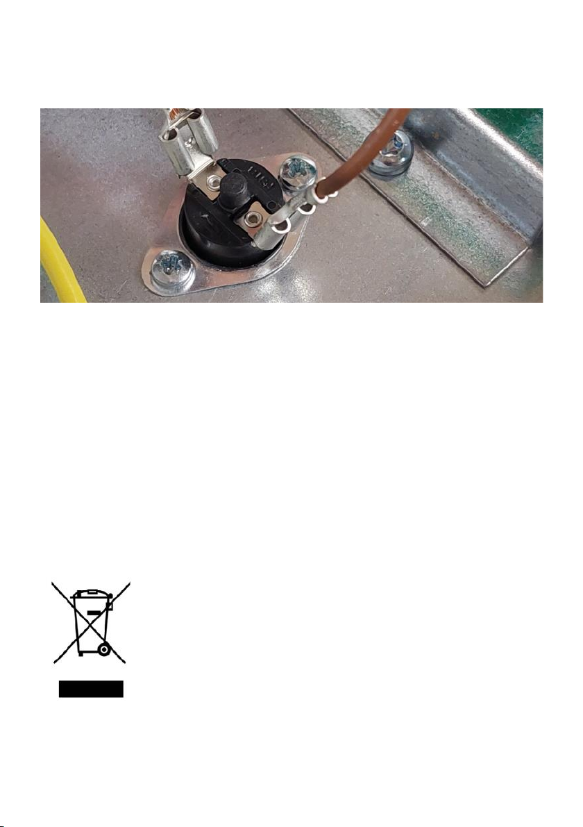
Overheating
If the temperature limiter has been triggered due to overheating, re-
set as follows:
1. Disconnect the electricity from the heater.
2. Investigate the matter and repair the fault.
3. Reset by opening the lid and pushing the button on top of the
temperature limiter (gure 11) until a click sound is heard.
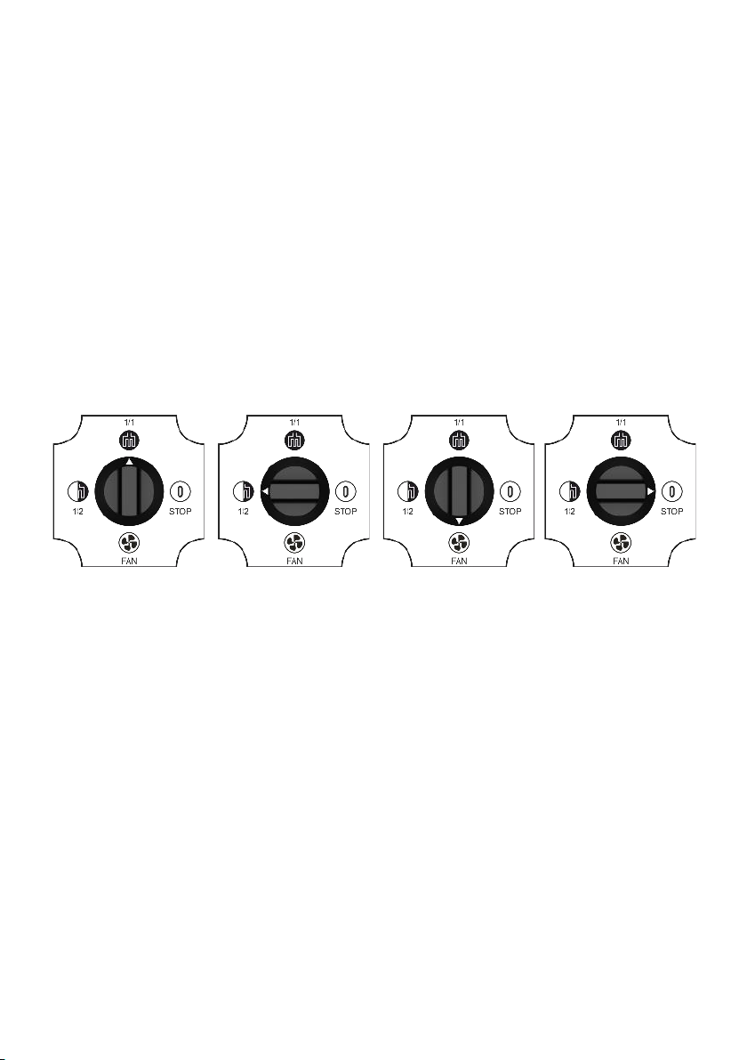
Figure 10. Control box available options.
A. Heating 100% B. Heating 50% D. Off
C. Fan mode
13
Maintenance
Clean the space heater with compressed air when it is disconnected
from the mains. If necessary, wipe the case with a damp cloth and mild
detergent. Do not use solvents or abrasives. Dry well before turning it
back on.
Guaranty
KEEP VALID RECEIPT OR GUARANTEE CARD
To obtain guarantee cover within the guarantee period, it is an abso-
lute must that either a valid receipt or the guarantee card is submitted
to the service center together with the appliance.
This symbol on Inelco product or its packaging means that the
product should not be disposed of with your other household
waste. It is your responsibility to dispose of your waste equip-
ment separately from the municipal waste stream.
The correct disposal of your end-of-life equipment will help pre-
vent potential negative consequences for the environment and
human health.
All trademarks, logos and brand names are the property of their re-
spective owners. All company, product and service names used in this
manual are for identication purposes only.
Figure 11. Temperature limiter.
14
15
All trademarks, logos and brand names are the property of their re-
spective owners. All company, product and service names used in this
manual are for identication purposes only.
Mains voltage [V]: 230V 50Hz
Max mains current [A]: 14.3A
Fan diameter [mm]: 230
Air ow [m3/h] 400
Product size [mm] 410x300x260
Heating power [kW]: 1,65kW/3.3kW
Protection class IP IP44
Technical data:

16
Systemowa nagrzewnica
stacjonarna Dania SSH 3.3kW Produkt 88843067 TYP 2210
Ważne: przed użyciem, naprawą lub czyszczeniem urzą-
dzenia przeczytaj instrukcję obsługi w całości.
Niewłaściwe użytkowanie może spowodować obrażenia,
oparzenia, porażenie prądem lub pożar. Urządzenie nie jest prze-
znaczone do użytku przez osoby (w tym dzieci) o ograniczonych
możliwościach zycznych, sensorycznych lub umysłowych, a także
nieposiadające doświadczenia i wiedzy, chyba że znajdują się pod
nadzorem lub zostały poinstruowane w zakresie obsługi urządzenia
przez osobę odpowiedzialną za ich bezpieczeństwo. Dzieci należy
nadzorować, aby mieć pewność, że nie bawią się urządzeniem.
Zachowaj tę instrukcję w bezpiecznym miejscu do wykorzystania w
przyszłości.
OSTRZEŻENIA DOTYCZĄCE BEZPIECZEŃSTWA!
Nie zakrywać – niebezpieczeństwo pożaru!
Urządzenie podczas pracy ma gorące powierzchnie!
Upewnij się, że obszar wokół kratki wlotowej i wylotowej jest wolny
od materiałów, które mogłyby utrudniać lub zatrzymywać przepływ
powietrza przez urządzenie.
Nie umieszczaj nagrzewnicy w miejscu, gdzie na obudowie lub w je-
go pobliżu mogą znajdować się materiały łatwopalne!
Urządzenia nie wolno przykrywać odzieżą ani podobnym materiałem,
ponieważ przegrzanie urządzenia może spowodować ryzyko pożaru.
Nie używaj nagrzewnicy w bezpośrednim sąsiedztwie wanny, prysz-
nica lub basenu!
Nie zakrywać nagrzewnicy, nie może być ona narażona na działanie
nadmiernego kurzu i wilgoci!
Nie używaj nagrzewnicy na zewnątrz budynków!
Nie umieszczaj nagrzewnicy bezpośrednio pod gniazdkiem!
Użyj dedykowanego uchwytu do umocowania nagrzewnicy na ścia-
nie.
Nie używaj nagrzewnicy, jeśli została upuszczona!
Nie używaj, jeśli na nagrzewnicy widoczne są oznaki uszkodzenia
Nagrzewnica może być otwierana i demontowana wyłącznie przez
producenta lub wykwalikowanego inżyniera serwisu!
Kabel zasilający może podłączyć lub wymienić wyłącznie wykwali-
kowany specjalista!
PL
17
Rysunek 1. Opis elementów urządzenia.
1. Dioda kontrolna LED
2. Element grzejny
3. Śruba mocująca uchwyt
4. Kabel zasilający
5. Zaślepka otworu na kabel urządzenia sterującego
6. Wentylator z silnikiem
7. Uchwyt do mocowania naściennego
8. Regulacja pochylenia w pionie
9. Kratka wylotowa
10. Kratka wlotowa

18
Przeznaczenie
Elektryczne systemowe nagrzewnice stacjonarne DANIA SSH są prze-
znaczone do użytku wyłącznie wewnątrz pomieszczeń. Nadają się do
ogrzewania magazynów, hal produkcyjnych, warsztatów, pomieszczeń
magazynowych, pomieszczeń socjalnych, salonów wystawowych, gara-
ży itp.
Działanie
Przepływ powietrza przez nagrzewnicę wymuszany jest za pomocą
wentylatora (rysunek 1 poz. 6). Przepływające powietrze jest podgrze-
wane przez elementy grzejne (rysunek 1 poz. 2), których praca jest re-
gulowana za pomocą zewnętrznego termostatu i Control Boxa. Pręd-
kość przepływu powietrza nie jest regulowana.
Dostępne są dwa tryby pracy wentylatora:
1. wentylator pracuje tylko wtedy, gdy elementy grzejne są włączone
2. wentylator pracuje cały czas - nawet gdy termostat wyłączy elemen-
ty grzejne.
Aby uzyskać szczegółowe informacje, patrz odpowiednio rysunek 5 lub
rysunek 6.
Inelco zaleca użycie termostatu Salus 091FLV2 z programatorem do
sterowania nagrzewnicami stacjonarnymi DANIA SSH. Więcej szcze-
gółów można znaleźć na rysunku 9.
Ważne: aby pracować nagrzewnica musi być połączona z
Control Box oraz z zewnętrznym termostatem. Jeden Control
Box i jeden termostat zewnętrzny mogą sterować jedną na-
grzewnicą lub zespołem obejmującym do 6 nagrzewnic.
Włączanie i wyłączanie, wybór połowy lub pełnej mocy grzania oraz
wybór trybu wentylatora odbywa się za pomocą Control Boxa, który
jest montowany na ścianie w celu zapewnienia łatwego dostępu.
Szczegółowe informacje znajdują się na rysunku 10. Nagrzewnice są
zabezpieczone przed przegrzaniem poprzez wbudowany ogranicznik
temperatury. W sytuacji zadziałania tego zabezpieczenia, aby je zrese-
tować, wykonaj czynności opisane w rozdziale Przegrzanie.

19
Nagrzewnica montowana jest na ścianie za pomocą uchwytu ścienne-
go, który umożliwia uzyskanie 3 różnych pozycji w pionie i 3 różnych
pozycji w poziomie – patrz rysunek 3 i rysunek 4.
Instalacja mechaniczna
Nagrzewnice stacjonarne DANIA SSH 3,3kW przeznaczone są do mon-
tażu naściennego. Urządzeń nie należy umieszczać bezpośrednio pod
gniazdem zasilania. Należy zachować minimalne odległości podane na
rysunku 2. Nagrzewnic nie wolno montować na sucie.
Zaznacz lokalizację otworów na ścianie korzystając z uchwytu ścienne-
go jako szablonu. Wywiercić otwory na kołki mocujące. Zamontuj
uchwyt na ścianie za pomocą odpowiednich kołków mając na uwadze
żądane położenie w poziomie (ewentualne odchylenie w lewo lub w
prawo). Zamontuj nagrzewnicę w uchwycie i wyreguluj jej położenie w
pozycji pionowej (patrz rysunki 3 i 4). Wkręcić dolną śrubę i dokręcić
wszystkie śruby.
Należy używać elementów mocujących odpowiednich do materiału
ściany i ciężaru urządzenia, zachowując niezbędny margines bezpie-
czeństwa.

20
Rysunek 2. Montaż na ścianie. Minimalne odległości.
Aby zapewnić nagrzewnicy odpowiednie warunki pracy należy za-
chować minimalne odległości od sutu, ścian pomieszczenia znajdu-
jących się po bokach oraz minimalną wysokość miejsca montażu.
Właściwe umiejscowienie nagrzewnicy zapewni efektywne i równo-
mierne ogrzewanie pomieszczenia, bezpieczeństwo użytkowania
oraz zabezpieczy przechodzące osoby przed możliwością kolizji z
urządzeniem.
Zalecane minimalne odległości to:
1. 0,3 m od sutu
2. 1,0 m od ścian bocznych
3. Minimalna wysokość montażu od podłogi wynosi 1,8 m lub więcej
w zależności od procesów zachodzących w pobliżu nagrzewnicy.
Table of contents
Languages:
Other Inelco Heater manuals


 Operation and maintenance instructions")
