Solo Golden Tube Audio SE-40 User manual

Golden Tube Audio SE-40
Page 2of 36
Preface ....................................................................................................................................................................3
Document Control...............................................................................................................................................3
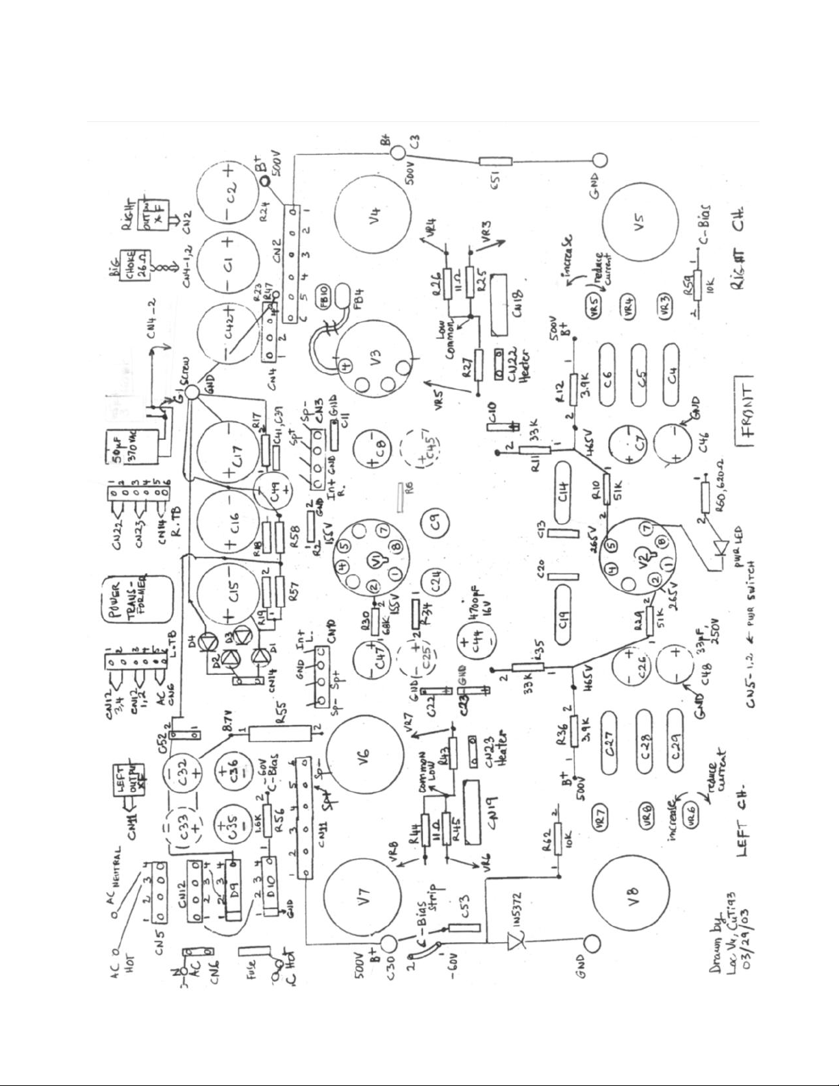
SE-40 Original Parts Diagram ..................................................................................................................................4
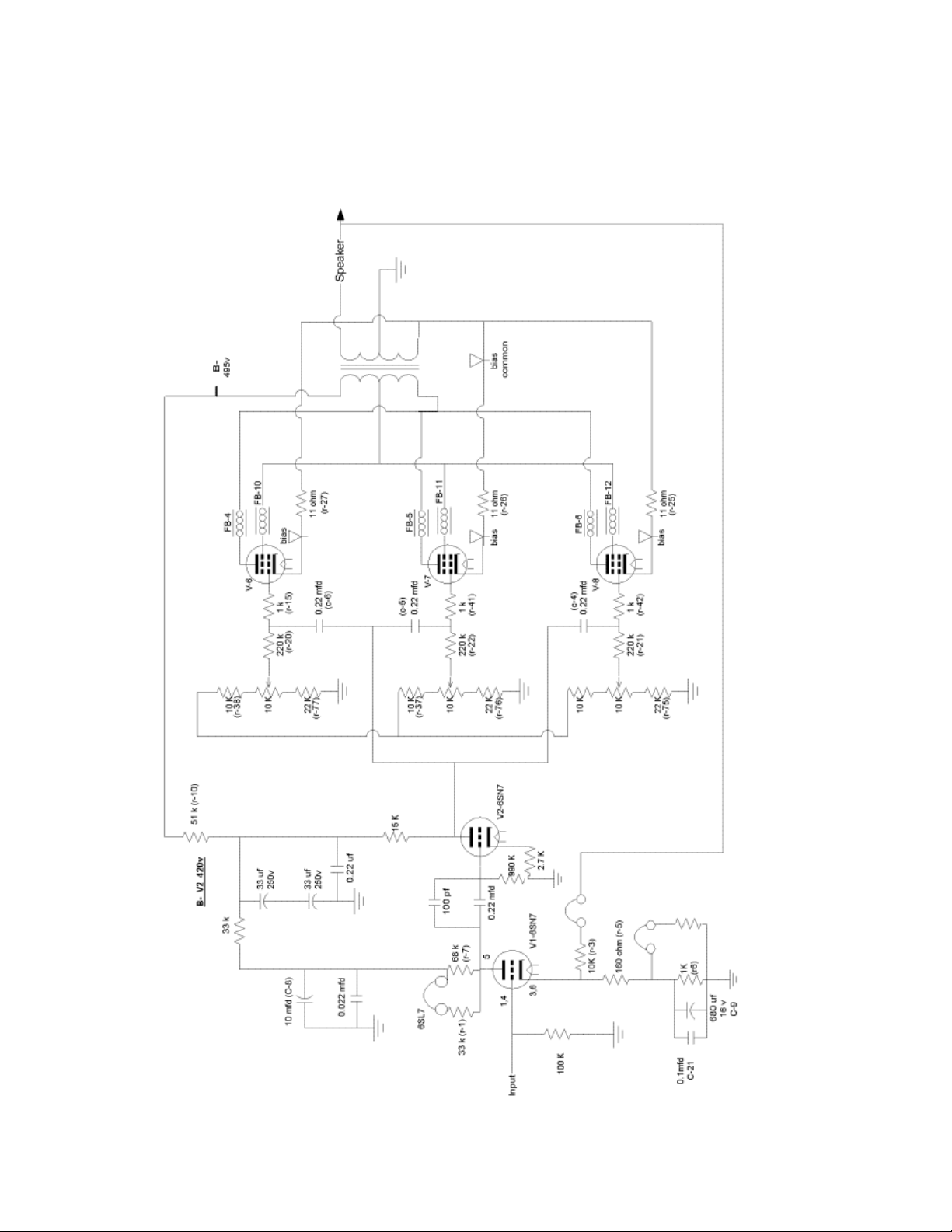
Left Channel Schematic...........................................................................................................................................5
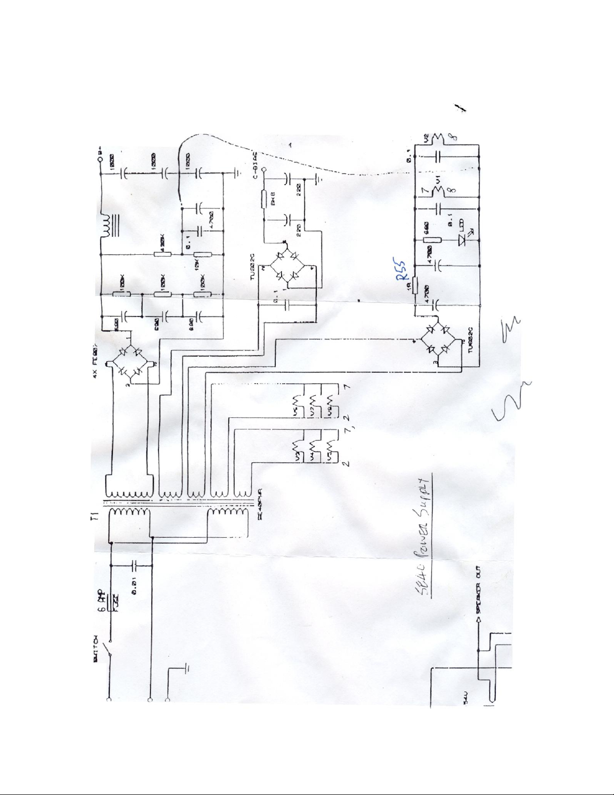
Power Supply Schematic.........................................................................................................................................6
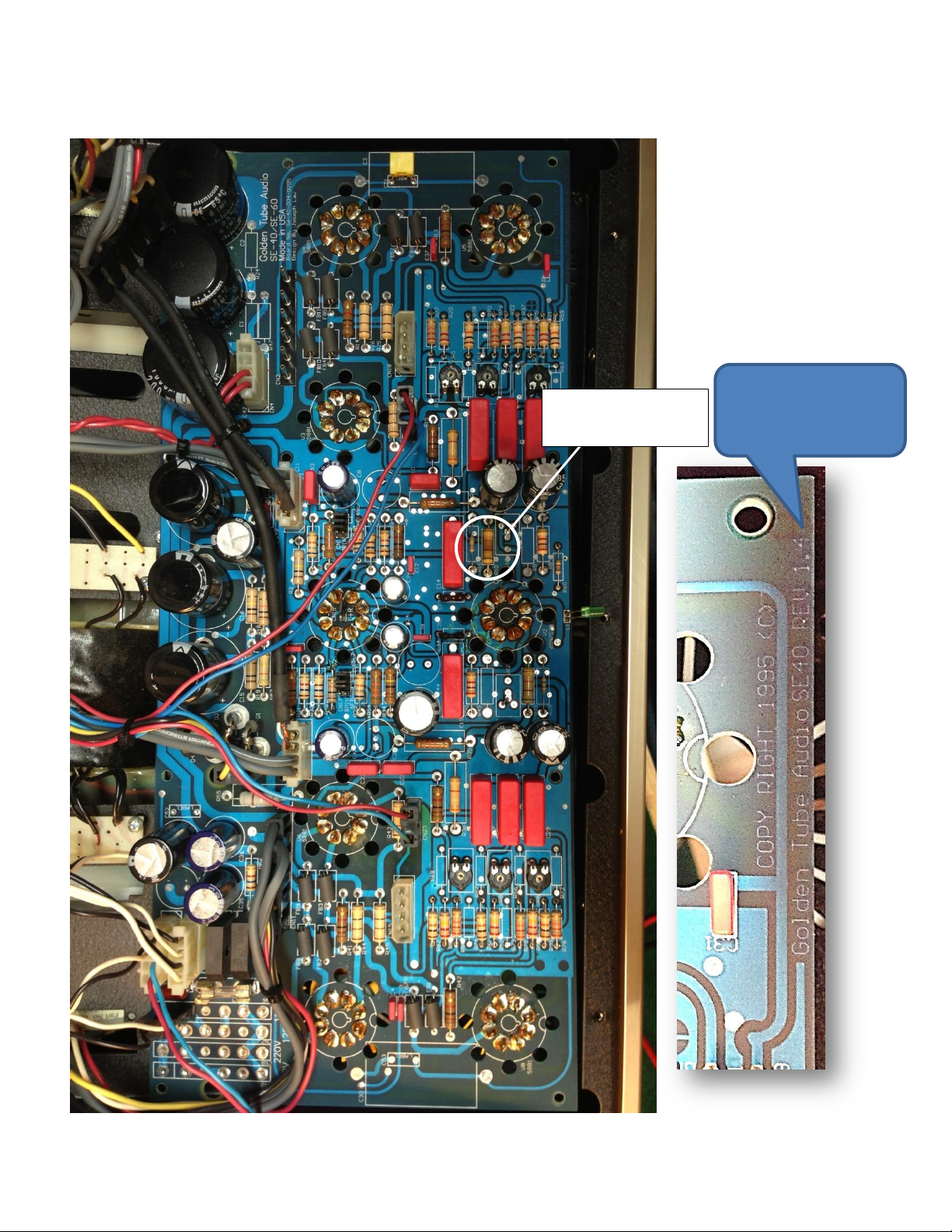
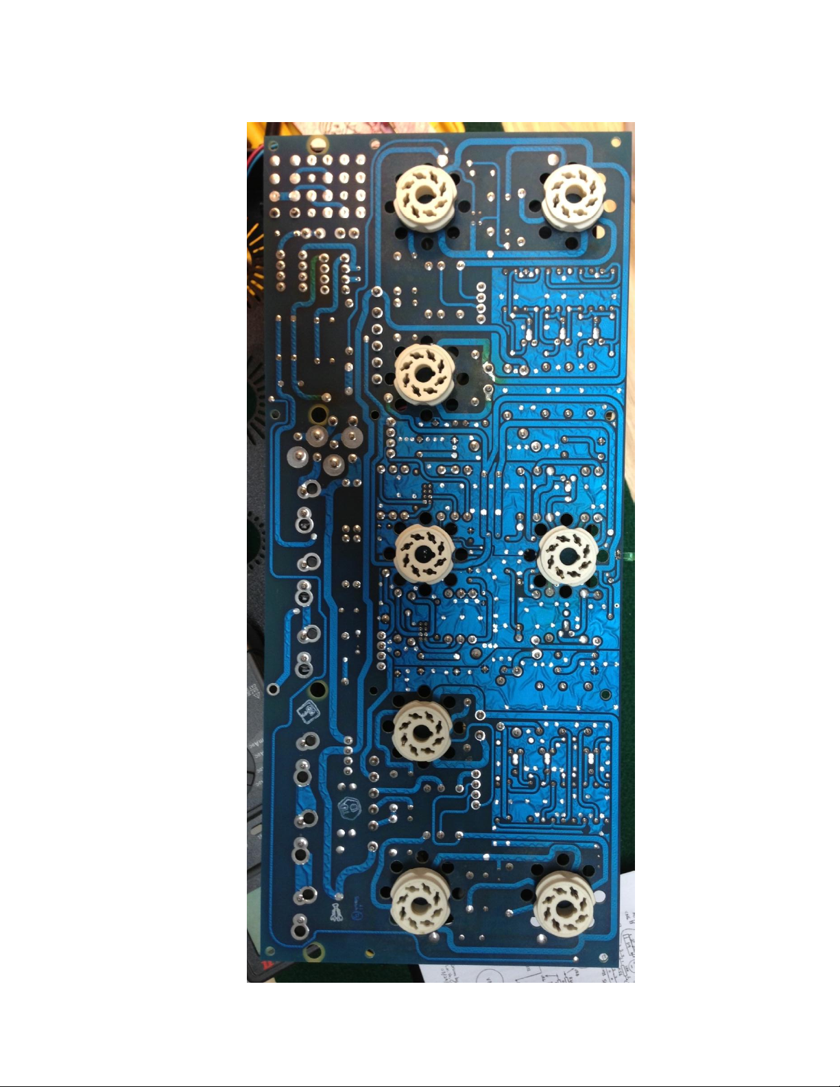
Original Circuit Board v1.4 –Bottom Side ..............................................................................................................7
Original Circuit Board v1.4 –Top Side ....................................................................................................................8
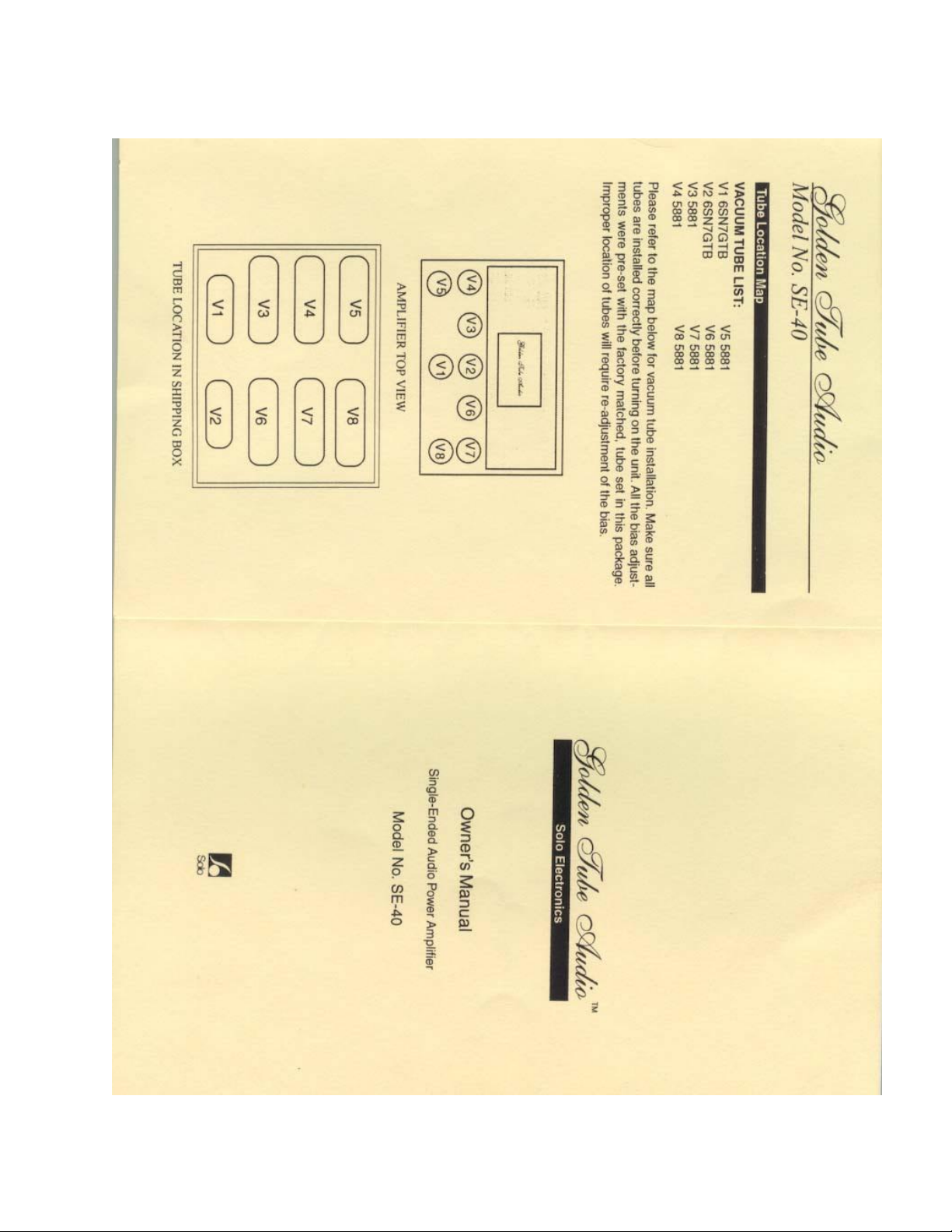
SE-40 Owner’s Manual............................................................................................................................................9
Biasing the Amp ....................................................................................................................................................20
What is the Proper Bias Set Value?...................................................................................................................20
Before Starting..................................................................................................................................................20
Tools Needed ....................................................................................................................................................20
Removing the Bottom Cover.............................................................................................................................21
Setting the Bias .................................................................................................................................................22
Underneath GTA SE-40 .....................................................................................................................................23
Red Plate Condition ..........................................................................................................................................24
Replacing Tubes ....................................................................................................................................................25
Factory Tubes....................................................................................................................................................25
Factory Output Tube Cross-Reference..............................................................................................................26
Factory Selectable Input Tubes.........................................................................................................................26
Tube Swapping......................................................................................................................................................27
Other 6L6 Varieties ...........................................................................................................................................27
Troubleshooting....................................................................................................................................................28
Dead channel ....................................................................................................................................................28
Hum...................................................................................................................................................................29
Red Glowing Tubes ...........................................................................................................................................29
Low gain ............................................................................................................................................................29
Static Noise .......................................................................................................................................................29
References ............................................................................................................................................................30
Appendix - Sovtek Tube Specs ..............................................................................................................................32

Golden Tube Audio SE-40
Page 3of 36
Preface
This service manual is an open source collaboration effort of the members of the Golden Tube community
group at http://groups.yahoo.com/neo/groups/golden_tube/info
This manual is a collection of contributions from various forum members edited and consolidated into on
handy guide to assist in the self-support of maintaining the highly regarded Golden Tube Audio SE-40 amplifier
manufactured by the now defunct Solo Electronics of Hayward California in the 1990’s.
Though the best efforts of the community were involved in making this manual and reviewing and editing it’s
contents, it is possible errors or omissions herein could be present.
As always, proceed with caution and consult a certified technician experienced with tube electronics should
you have any doubts or concerns about your own skill or ability. Even though audio tube technology is 100
years old, thousands of factory new tube audio gear is sold annually. Consult Ham radio shops, guitar shops,
and specialty Hifi shops to locate a qualified technician in town.
Document Control
Version
Published
Date
Change Control
1.0
09-10-2013
First version follow draft review
1.1
09-10-2013
Added Sovtek Tube Specification section
1.2
09-23-2013
Edited Tube Cross-ref section for clarity; within Reference section added Parts
suppliers
1.3
09-27-2013
Selectively edited for grammar and clarity, resolved a broken link, replacement
tube cross-reference chart

Golden Tube Audio SE-40
Page 4of 36
SE-40 Original Parts Diagram
Parts Placement and Key Test Points

Golden Tube Audio SE-40
Page 5of 36
Left Channel Schematic
GTA built versions from 1.0 to 1.4. It’s unknown which version this schematic pertains. There is debate how
accurate this drawing may be or for which version.

Golden Tube Audio SE-40
Page 6of 36
Power Supply Schematic

Golden Tube Audio SE-40
Page 7of 36
Original Circuit Board v1.4 –Bottom Side
Board pics on Pages
6 & 7 are version 1.4
Burnt R10
51K Carbon Resistor

Golden Tube Audio SE-40
Page 8of 36
Original Circuit Board v1.4 –Top Side

Golden Tube Audio SE-40
Page 9of 36
SE-40 Owner’s Manual

Golden Tube Audio SE-40
Page 10 of 36

Golden Tube Audio SE-40
Page 11 of 36

Golden Tube Audio SE-40
Page 12 of 36

Golden Tube Audio SE-40
Page 13 of 36

Golden Tube Audio SE-40
Page 14 of 36

Golden Tube Audio SE-40
Page 15 of 36

Golden Tube Audio SE-40
Page 16 of 36

Golden Tube Audio SE-40
Page 17 of 36

Golden Tube Audio SE-40
Page 18 of 36

Golden Tube Audio SE-40
Page 19 of 36

Golden Tube Audio SE-40
Page 20 of 36
Biasing the Amp
What is the Proper Bias Set Value?
The bias values recommended in this service manual are intended for factory tubes or factory equivalent
tubes. Maximum bias for factory tubes is 640mV, given drift and fluctuation the bias should be no more
630mV.
Quoting Loc, “Some tubes reach their stable bias sooner than others, the final/stable state is about 20 minutes
after turn on, so just go back & forth across all 6 tubes to set them within 10 mV of each other. With long use,
tube bias can drift by 20mV in difference; if more than 20mV of variance, then re-adjusting is needed. There is
no clear cut limit, just an approximate”.
Helpful insight from Loc…
Some tubes are more sensitive than others, since all 6 tubes share one common source B+ for current,
some could draw more bias and read higher than 640mV, and others will read lower. This is normal, just
adjust the other tubes to raise the bias, then it will reduce the current goes to the higher sensitive
tube(s). I recommend the value of 600mV and with 10% tolerance; it could be between 540 to 660mV.
Remember that the bias does not need to be accurate. If measuring the bias when playing music, you will
see how the bias fluctuates. The bias should be stable and not jumping around or continues to increasing
higher. As long as bias operates less than 20mV from each other, it’s OK, people tend to be perfect right
on the dot, there is no audible difference if tubes within 20 mV of bias to each other per channel.
Before Starting
The following is a procedure to bias the SE-40:
Inspect the tubes for any discoloring, damage, loose glass to base, etc. It may even be a good time to test
tubes in a tube tester.
After handling the tubes, they should be carefully wiped clean of dust and finger prints. This promotes
even heat dissipation and aids visual inspection too.
The trim pots work backwards from what you probably expect (!). eg, Counter-clockwise increases the
gain.
The nomenclature of the trim pots and the valves are not intuitively labeled.
Important: Page 12 of the factory manual shows the bias harness pin-out from the female side of the
connector and not the male connector on the circuit board. Use the diagram below for reference.
Tools Needed
Small plastic slotted screwdriver for Trim pot tuning
#2 Phillips screwdriver for chassis bottom cover removal
Digital multi-meter
(2) Original factory biasing connector & cable or an after-market PC
5.25” hard drive power splitter cable
Soft clean cloth
Plastic nitrate gloves to protect from electrical shock
Plastic Screwdriver
Table of contents