Solt SR5-BPR User manual

User's Guide
■ Thank you for purchasing Solt wireless calling system products.
■ Please read this user's quide carefully before using and follow the instructions.
■ Specification and instructions are subject to change without notice.
SR5-BPR

3
.................................................
.............................................................
......................................................................
...............................................................
..........................................................
....................................................
.........
........................................
..................................
.............................................
.................................
Important Safety Instructions
Name of each Part
Components
Type of set mode
E1. Frequency setting
E2. Call bell ID registration
E3. Setting of the time for prevention of duplicate reception
E4. Transmission delay time setting
E5. Individual deletion of the call bell ID
E6. [No Receive] bell ID setting
Installation guide and notice for attention
3
4
5
5
6
7
8
9
10
11
12
Contents
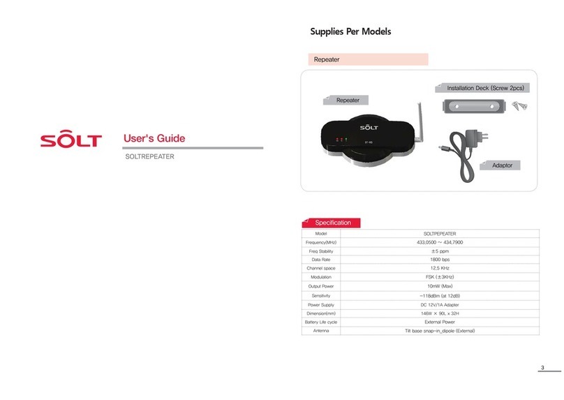
Specification
Model SR5-BPR
Frequency(MHz) CE, FCC : 433.1500 / 434.6500
KC : 447.8750 / 447.9750
Freq Stability ±5 ppm
Data Rate 1800 bps
Channel space 12.5 KHz
Modulation FSK (±3KHz)
Output Power 10mW (Max)
Sensitivity -118dBm (at 12dB)
Power Supply DC 12V/1A Adapter
Dimension(mm) 146W × 90L x 32H
Battery Life cycle External Power
Antenna Tilt base snap-in_dipole (External)
Be sure to unplug the power plug while
holding it firmly. If cord is unplugged
by pulling out, some parts of the cord
can be disconnected and it may cause
risky situation. [
It may cause fire.
]
Do not touch the power plug with
wet hand.
[There is a risk of electric shock.]
Power precautions
Warning
Warning
Warning
Caution
Caution
Caution Caution
Caution
Caution
Caution
Caution
Caution
Be sure to insert the power plug to
the end of the inner part.
[If the connection is unstable, it may
cause fire.]
Do not use one socket for multiple
devices at the same time. [It may cause
fire due to overheating of the socket.]
Do not separate, repair or remodel the
product by user own decision. In case
repair is needed, contact service cen-
ter. [It may cause fire or electric shock.]
not press or scrape the screen surface
strongly with hand or sharp object (nail,
pencil, pen, etc.) [The screen surface
can be damaged or it can cause failure.]
If power plug is dropped or case is
broken, unplug the power cord. [If it is
used as it is, it may cause fire or
elec-
tric shock. Please contact service center.]
Do not spray inside or outside of the
product with water or clean it with
benzene or thinner. [This can lead to
poor insulation of the electric device
and cause electric shock or fire.]
Do not install the product at humid,
dusty or watery place. [It may cause
an electric shock or fire.]
If possible, avoid installing the product
at the place near to metal sheet,
wire or LED light. [Distance between
transmission and reception can be
shortened depending on surrounding
environment.]
If inside of the product is exposed to
water or foreign substance, contact
service center. [There is the risk of
fire or electric shock due to the
damage to internal components.]
In case of thunderstorm or lighting or
if the power plug is not used for long
time, unplug the power cord. [There is
the risk of electric shock or fire.]
Warning
Caution
This is for the case with the possibility of serious injury or death if this is not observed.
This is for the case with the possibility of minor injury or damage to the product
if this is not observed.
Safety Instruction contains the information to prevent the unexpected risk or damage in
advance by using the product in correct way and it should always be observed all the times.
Important Safety Instructions
Use precautions

4 5
.&/6
&4$ ⶸⶼⶾ ⶺ
4&5
183
② Status Indicating light
Name for each part
Top side
Bottom side
① Folding antenna: 180 degree rotation and angle
adjustment can be done.
⑤ User setting button
③ Bracket fixing hole
④ Set screen window
⑥ Adapter Input: DC12V 1A
(Please be sure to use the adapter
provided with the product.)
Adapter is one of expendable supplies.
When necessary, please purchase an adapter with DC12V 1A
PWR Red light when the power is on
RX Waiting for reception : Red light flashing
TX During transmission : Red light flashes and
then light off
MENU
ESC
·Menu button for setting mode
·
English/ numeric change button
▲ ▼ ·Up/Down direction button
◀ ▶ ·Left / Right direction button
SET
PWR
·set value saving button
·Power ON/OFF button
DC12V 1A
[Picture of bracket mounting]
[Back side cover]
Type of set mode
User can set following modes with user set button.
E1 FrEq
Frequency setting
The function to set the frequency of the repeater.
E2 rEgT
Call bell ID registration
The function to register the ID of the call bell to be relayed.
E3 dUPT
Setting of the time for prevention of duplicate reception
(Default setting is 5 seconds)
The function to restrict reception for call from the same call bell.
E4 TXdT
Transmission delay time setting (TX Delay Time)
The function to set the delay time of the transmission after receiving call.
E5 dELE
Individual deletion of the call bell ID
The function to delete registered call bell individually.
E6 NOrX
[No Receive] bell ID setting
The function to set the call bell which user does not want to receive among
the registered call bells.
Main body
Components
Adapter
Bracket
(with 2 screws)

6 7
Frequency setting
·The function to set frequency of the repeater.
·[E1 FrEq] is displayed on the screen.
·[E1 FrEq] is displayed on the screen.
※
default frequencies :
·[-------] is displayed on the screen.
·The frequency regulated by certification
body is displayed.
⑴ Press the MENU button and enter the setting mode.
⑵ Press the SET button at [E1].
⑶ Select the frequency with up/down button (▲ ▼).
⑷ Press SET button, then set value is saved.
⑸ Press MENU button, then it turns to standby for reception status.
MENU
ESC ▲◀ ▶ SET
PWR
▼
MENU
ESC ▲◀ ▶ SET
PWR
▼
MENU
ESC ▲◀ ▶ SET
PWR
▼
MENU
ESC ▲◀ ▶ SET
PWR
▼
MENU
ESC ▲◀ ▶ SET
PWR
▼
·The set default frequencies are different as
per the certified model as follow;
CE model 4346500
FCC model 4346500
KC model 4479750
⑸ After completion of the registration, press the SET button.
⑹ Press MENU button, then it turns to standby for reception status.
Call bell ID registration
·The function to register the ID of the call to be relayed.
·[E1 FrEq] is displayed on the screen.
·[E2 rEgT] is displayed on the screen,
and then "1" flashes.
⑴ Press the MENU button and enter the setting mode.
⑵
Select [E2] mode with Upward (▲) button and press SET button, and then "1" flashes.
⑶
Set the number (bell ID) you want with Up/Down, Left/Right (▲▼◀▶) and MENU button.
MENU
ESC ▲◀ ▶ SET
PWR
▼
MENU
ESC ▲◀ ▶ SET
PWR
▼
MENU
ESC ▲◀ ▶ SET
PWR
▼
Number
Alphabet
Left / right (◀▶) button
Press MENU button for three seconds
Number / Alphabet that can be expressed
Move digit number
Number and alphabet conversion
(Ex: When "1" is registered, and then number on the screen is automatically increased
to '2'.
When 'A' is registered, it is automatically increased to 'b' on the screen.)
·In order to register a bell as automatically increased number repeat process (4)
and for registration for other numbers repeat process (3) and (4).
⑷
When call bell button to be registered is pressed, set number is registered
with a "beep" sound and number is automatically increased to the number
next to the registered number and it is displayed on the screen.
·[E2 rEgT] is displayed,
and then [-------] is displayed.
MENU
ESC ▲◀ ▶ SET
PWR
▼

8 9
·[E3 dUPT] is displayed on the screen.
⑷ Press SET button,and then set value is saved.
⑸ Press MENU button, then it turns to standby for reception status.
MENU
ESC ▲◀ ▶ SET
PWR
▼
MENU
ESC ▲◀ ▶ SET
PWR
▼
Setting of the time for prevention
of duplicate reception
·The function to restrict reception of the same call bell
during set time.
·[E1 FrEq] is displayed on the screen.
·[E3 dUPT] is displayed on the screen.
·Set number is displayed on the screen.
⑴ Press the MENU button and enter the setting mode.
⑵ Browse [E3] mode with UP (▲) button and press SET button.
⑶ Set the desired set value with up/down button (▲▼).
MENU
ESC ▲◀ ▶ SET
PWR
▼
MENU
ESC ▲◀ ▶ SET
PWR
▼
MENU
ESC ▲◀ ▶ SET
PWR
▼
·[-------] is displayed on the screen.
Default setting is 5 seconds and [005] is
displayed on the screen.
·[E4 TXdT] is displayed on the screen.
·[-------] is displayed on the screen.
Transmission delay time setting
·The function to set delay time for transmitting
after receiving call bell.
·[E1 FrEq] is displayed on the screen.
·[E4 TXdT] is displayed on the screen.
·Set number is displayed on the screen.
⑴ Press the MENU button and enter the setting mode.
⑵ Browse [E4] mode with UP (▲) buttons, and then press SET button.
⑶ Set desired set value with up/down button (▲▼).
MENU
ESC ▲◀ ▶ SET
PWR
▼
MENU
ESC ▲◀ ▶ SET
PWR
▼
MENU
ESC ▲◀ ▶ SET
PWR
▼
⑷ Press SET button, and then set value is saved.
⑸ Press MENU button, then it turns to standby for reception status.
MENU
ESC ▲◀ ▶ SET
PWR
▼
MENU
ESC ▲◀ ▶ SET
PWR
▼
Default set value is 2 seconds and [020] is
displayed on the screen.

10 11
·To delete another call bell ID, (3) and (4)
process is needed to be repeated.
⑷ When the right (▶) button is pressed, then selected ID is deleted
and a beep sound output is made.
MENU
ESC ▲◀ ▶ SET
PWR
▼
Individual deletion of the call bell ID
·The function to delete registered call bell individually.
·[E1 FrEq] is displayed on the screen.
·After [E5 dELE] is displayed on the screen,
then the call bell ID registered at the first is
displayed on the screen.
·The call bell ID selected is displayed
on the screen.
⑴ Press the MENU button and enter the setting mode.
⑵ Browse [E5] mode with up (▲) button and press SET button,
then the call bell ID registered at the first is displayed.
⑶ Select the call bell ID to be deleted with Up/Down (▲▼) button.
MENU
ESC ▲◀ ▶ SET
PWR
▼
MENU
ESC ▲◀ ▶ SET
PWR
▼
MENU
ESC ▲◀ ▶ SET
PWR
▼
⑸ When MENU button is pressed after pressing SET button, it turns to
standby for reception status.
MENU
ESC ▲◀ ▶ SET
PWR
▼
·[E5 dELE] is displayed,
and then [-------] is displayed.
·The call bell ID selected is displayed
on the screen.
·[E6 NOrX] is displayed,
and then [-------] is displayed.
[No Receive] bell ID setting
·The function to set call bell which user does not
want to receive among the registered call bells.
·[E1 FrEq] is displayed on the screen.
⑴ Press the MENU button and enter the setting mode.
⑶ Select the call bell ID not to be received with Up/Down (▲▼) button.
MENU
ESC ▲◀ ▶ SET
PWR
▼
MENU
ESC ▲◀ ▶ SET
PWR
▼
⑷
Set "to be received/ not to be received" with the right direction (▶) button.
⑸ When MENU button is pressed after pressing SET button, it turns to
standby for reception status.
MENU
ESC ▲◀ ▶ SET
PWR
▼
MENU
ESC ▲◀ ▶ SET
PWR
▼
· Whenever right direction (▶) button
is pressed, ( ) icon is on
and off in turn and the ID set by the icon
is not received.
/P3FDFJWF
·After [E6 NOrX] is displayed on the screen,
then the call bell ID registered at the first is
displayed on the screen.
⑵ Browse [E6] mode with UP (▲) button and press SET button,
then the call bell ID registered at the first is displayed.
MENU
ESC ▲◀ ▶ SET
PWR
▼

For smooth use of the product, be sure to install the product carefully together with attention
for followings.
Installation guide and notice for attention
Determining the location for installation
※ Install in the place with 100% reception rate.
※ Humidity or flooding is the cause of malfunctioning for this product, therefore, be sure to install the
product on the place water cannot reach.
If product should be installed outside of the building, be sure to install it under the eaves or on the
place where rain cannot reach.
As shown in the picture, it is most reliable to
install the product on the location A and in case
of location B, even though it is located within the
range of reception rate, it is unstable location
because it is close to border line.
Receiver location
100% reception rate
Fixing the cradle (Be sure to fix the cradle when the location for installation is determined.)
Placing the repeater on the fixed cradle (Fix it until you hear click sound.)
Connecting power supply (Be sure to use the adapter provided with the product.)
It is the best case when product is fixed on the ceiling as shown in the picture above and
antenna points downward, and in case this is not possible, installs the product close to
ceiling as much as possible.
Other Solt Repeater manuals
