Solter OPTIMATIC User manual

MANUAL DE INSTRUCCIONES
INSTRUCCIONES PARA EL USO Y EL MANTENIMIENTO,
LEA ATENTAMENTE ESTE MANUAL ANTES DE USAR LA
PANTALLA PROTECTORA.
INSTRUCTION MANUAL
INSTRUCTIONS FOR USE AND MAINTENANCE, READ THIS
MANUAL CAREFULLY BEFORE USING THE PROTECTIVE
SCREEN.
MI-03102-08 10/2020

INTRODUCCIÓN
Agradecemos su deferencia hacia nuestra marca y esperamos le sea de gran utilidad la pantalla de soldadura
que acaba de adquirir. El presente manual de instrucciones contiene las advertencias necesarias para una
correcta utilización dentro de las máximas condiciones de seguridad para el operario. Los filtros de soldadura
SOLTER deben ser empleados por personal experto que conozca y comprenda los riesgos involucrados en la
utilización de las mismas. En caso de incomprensión o duda sobre este manual les rogamos que se pongan
en contacto con nosotros. La manipulación del filtro de soldadura conlleva un peligro importante de lesión.
Rogamos se abstenga de efectuar cualquier manipulación en el filtro o casco. Sólo personal técnicamente
preparado puede realizarlo.
SOLTER Soldadura, S.L. declina toda responsabilidad por prácticas negligentes en la utilización y/o
manipulación. Este manual debe adjuntarse y conservarse con el modelo de filtro adquirido. Estos filtros están
diseñados y aprobados de acuerdo con la Norma Europea EN 379.
Es responsabilidad de las personas que los utilicen y reparen que el producto no deje de cumplir los requisitos
de las normas mencionadas.
ANTES DE EMPEZAR A SOLDAR
Antes de usar cualquiera de los filtros de soldadura asegúrese de retirar los films de protección
correspondientes, mantenga limpia el área de visión y la parte frontal del filtro ya que ahí se encuentran los
sensores que se ocupan del oscurecimiento del filtro.
Inspeccionar todas las partes operativas antes de usar la pantalla y comprobar que no existen signos de
deterioro. Cualquier parte deteriorada debe sustituirse inmediatamente antes de su utilización. Verificar el
funcionamiento del filtro antes de cada uso.
Asegúrese también de que la sujeción del mismo a la pantalla de protección es correcta para evitar que el
mismo se pueda desprender ante cualquier impacto pudiendo provocar daños personales al usuario.
En caso de que el DIN de oscurecimiento del filtro sea regulable, ajuste correctamente antes de cualquier
aplicación, para saber el grado adecuado para todas las aplicaciones consulte el apartado TABLA DE
ELECCIÓN DE FILTROS SEGÚN APLICACIÓN del manual de la pantalla de protección.
CARACTERÍSTICAS TÉCNICAS
2
MODELO
OPTIMATIC 150
FLIP UP
OPTIMATIC 100
OPTIMATIC 55
OPTIMATIC 50
Policarbonato
110x90x8mm
110x90x8mm
110x90x8mm
110x90x8mm
Área de visión
89×39mm
96x39mm
96x39mm
91x39mm
CE
1/1/1/2
1/1/1/2
1/1/1/2
1/1/1/2
Oscurecimiento
Ajustable (DIN
4/9-13) INTERIOR
Ajustable (DIN
4/9-13)
Ajustable (DIN
4/9-13)
Fijo (DIN 11)
Tipo de
Alimentación
Placas solares y 1
pila recambiable
CR 2032
Placas solares y 1
pila recambiable
CR 2032
Placas solares
Placas solares
On / Off
Automático
Automático
Automático
Automático
Sensibilidad
Ajustable (Interior)
Ajustable (Interior)
Ajustable (Interior)
Ajustable (Interior)
Baja (LOW)
Alta (HIGH)
Velocidad Oscuro /
Claro
0,1s MIN
1,0s MAX
0,1s MIN
1,0s MAX
0,1s MIN
1,0s MAX
0,1s SLOW
0,8s FAST
Rango Temperatura
de trabajo
- 10ºC a + 60ºC
- 10ºC a + 60ºC
- 10ºC a + 60ºC
- 10ºC a + 60ºC
Peso
0,8 Kg
0,8 Kg
0,75 Kg
0,75 Kg
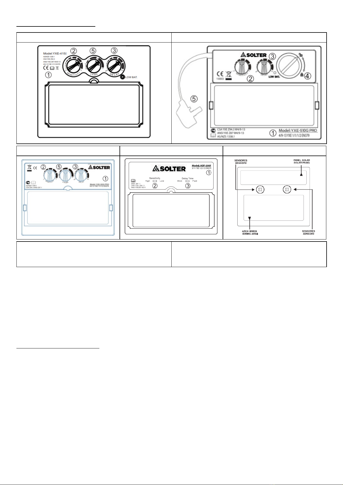
PARTES DE LOS FILTROS
Todos los filtros vienen marcados tal como indica el certificado CE de cada modelo. En este marcaje se
especifica con el primer número el grado de protección DIN que tiene el filtro cuando está en estado abierto
(claro), el siguiente número indica el grado DIN en estado cerrado (oscuro) indicando el grado mínimo y el
máximo. El símbolo que hay entre los dos números nos indica si el ajuste del grado DIN es manual o
automático. Los tres siguientes números nos indican el tipo de óptica, la dispersión de luz del filtro y la
homogeneidad de la visión del filtro según normativa.
Los tres números siguientes indican la Normativa Europea con la que cumple el filtro.
AJUSTES DE LOS FILTROS
Oscurecimiento .
En todos los modelos podemos ajustar el grado DIN manualmente.
El ajuste del grado DIN dependerá de la aplicación de la cual nos queramos proteger y de su potencia. El
grado DIN es el grado de oscuridad del filtro durante el proceso de soldadura.
Sensibilidad.
Ajusta la intensidad de luz necesaria para que el filtro pase de estado abierto a estado cerrado (oscuro). La
posición LOW la sensibilidad a la luz es baja, en posición HIGH la sensibilidad a la luz es alta.
Retraso.
Ajusta el tiempo que tarda el filtro en volver a estado abierto (claro) original una vez finalizado el proceso de
soldadura. Para el modelo OPTIMATIC 50 la posición SLOW el retraso es de 0,1s, en posición FAST el
retraso es de 0,8s. Para los modelos OPTIMATIC 100 / 55 el retraso se puede regular desde 0,1s hasta 1,0s.
3
OPTIMATIC 150 FLIP UP
OPTIMATIC 100
OPTIMATIC 55
OPTIMATIC 50
PARTE FRONTAL
1-Marcaje según normativa CE
3- Ajuste del retraso
5- Oscurecimiento
2- Ajuste sensibilidad
4- Pila intercambiable CR 2032
Funciones.
Algunos filtros permiten operar en dos modos de funcionamiento: Soldadura o amolado.
Amolado: Se usa para aplicaciones de amolado de materiales. En este modo, la función de oscurecimiento
está apagada. Lo que permite tener una visión clara con la seguridad de que la máscara protegerá la cara de
cualquier posible daño por proyecciones.
Soldadura: Se usa para la mayoría de aplicaciones de soldadura. En este modo, la función de
oscurecimiento está encendida. En el momento en el que perciba un ópticamente un arco, seleccione el nivel
de protección, el tiempo de retardo y el nivel de sensibilidad adecuado.
AJUSTE DEL ARNES
Altura del arnes (Posicion W)
Ajuste el arnés en la profundidad adecuada en la cabeza para asegurar un equilibrio correcto y estable.
Estrechar el arnés (Posición Y)
Pulse el botón de ajuste de la parte trasera del arnés y gire hacia la derecha o la izquierda hasta la posición
adecuada.
4
El modo amolado está pensado para realizar trabajos de amolado, no de soldadura.
Antes de volver a soldar asegúrese de volver a dejar la perilla en la posición de soldadura.
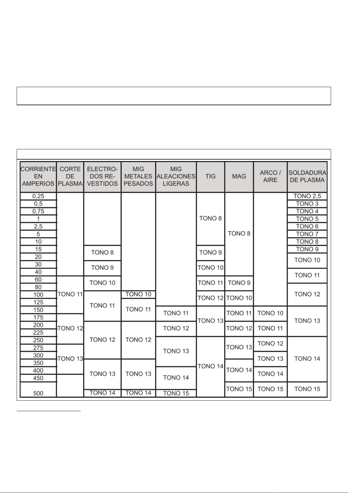
TABLA PARA ELECCIÓN DE FILTROS SEGÚN APLICACIÓN

Ajustar distancia (Posición Z)
Ajuste la distancia entre la cara y la lente aflojando por igual las dos tuercas exteriores y presione hacia
dentro para liberarlo de las ranuras de ajuste.
Ajuste del ángulo (Posición X)
Cuatro pernos en el lado derecho superior del arnés proporcionan un ajuste para la futura inclinación del
casco. Para ajustar, afloje la perilla de ajuste del lado derecho, a continuación, levante la pestaña del brazo de
control y muévelo a la posición deseada y finalmente vuelva a apretar la perilla de ajuste.
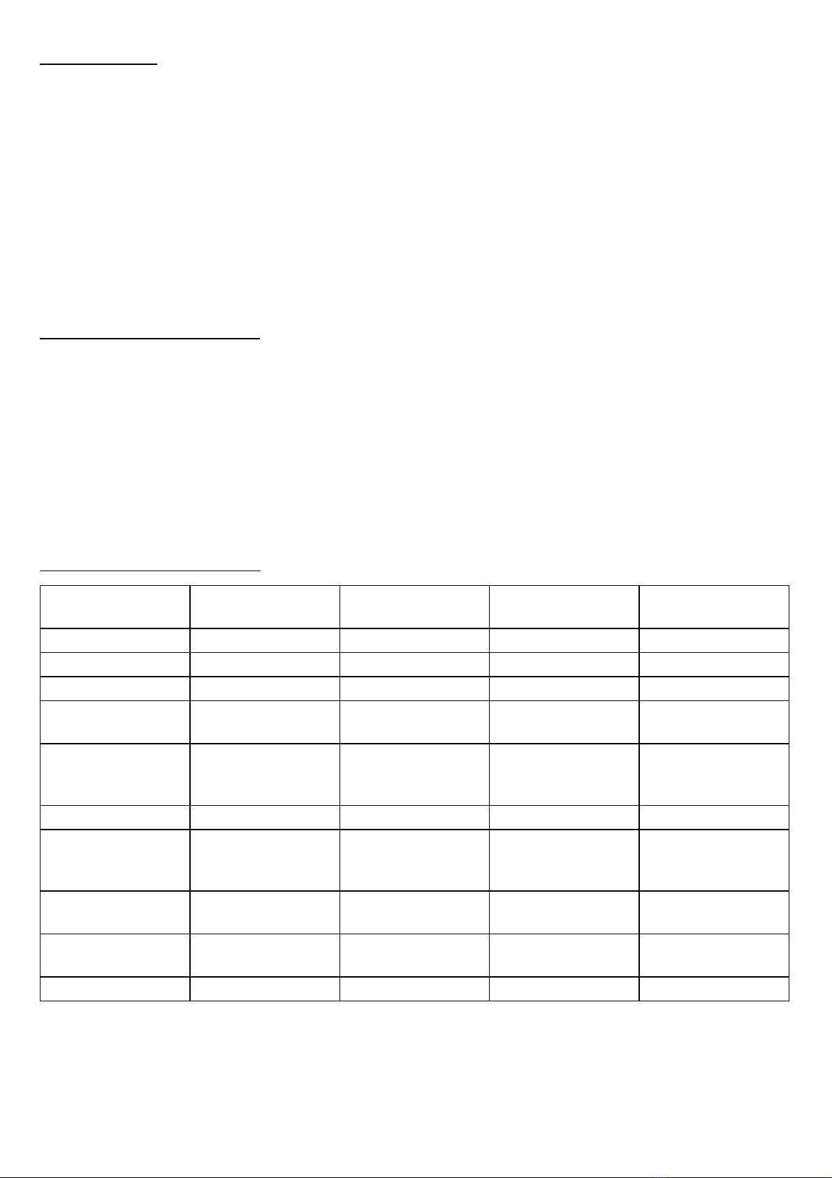
POSIBLES ANOMALÍAS
5
PROBLEMA
POSIBLES SOLUCIONES
Oscurecido irregular del filtro
La cinta de ajuste ha sido posicionada incorrectamente o el ángulo
del casco respecto a nuestra área de visión no es el adecuado.
El filtro no se oscurece o parpadea
(filtros automáticos)
El filtro protector frontal está dañado o en mal estado.
Los sensores están sucios.
La corriente de soldadura es demasiado baja.
Respuesta del filtro lenta
(filtros automáticos)
La temperatura ambiente de trabajo es demasiado baja.
Visión insuficiente
Los filtros protectores frontal o posterior están sucios.
Índice de protección incorrecto.
Insuficiente luz en el ambiente de trabajo.

DESPIECE
6
INTRODUCTION
We appreciate your deference to our brand and we hope the welding screen you have just purchased will be of
great use to you. This instruction manual contains the necessary warnings for correct use within the maximum
safety conditions for the operator. SOLTER welding filters must be used by expert personnel who know and
understand the risks involved in using them. In case of misunderstanding or doubts about this manual, please
contact us. Handling the weld filter carries a significant risk of injury. Please refrain from doing any
manipulation on the filter or helmet. Only technically trained personnel can do it.
SOLTER Welding, SL declines all responsibility for negligent practices in use and / or handling. This manual
should be attached and kept with the filter model purchased. These filters are designed and approved in
accordance with European Standard EN 379.
It is the responsibility of the people who use and repair them that the product does not fail to meet the
requirements of the aforementioned standards.
BEFORE STARTING TO WELD
Before using any of the welding filters be sure to remove the corresponding protection films, keep the viewing
area and the front part of the filter clean since there are the sensors that take care of the filter darkening.
Inspect all operating parts before using the display and check for signs of deterioration. Any damaged part
must be replaced immediately before use. Check the operation of the filter before each use.
Also make sure that the attachment to the protection screen is correct to prevent it from detaching in the event
of any impact, which could cause personal injury to the user.
In case the filter darkening DIN is adjustable, adjust correctly before any application. To find out the
appropriate degree for all applications, consult the section FILTER CHOICE CHART ACCORDING TO
APPLICATION of the protection screen manual.
TECHNICAL SPECIFICATIONS
7
MODEL
OPTIMATIC 150
FLIP UP
OPTIMATIC 100
OPTIMATIC 55
OPTIMATIC 50
Polycarbonates
110x90x8mm
110x90x8mm
110x90x8mm
110x90x8mm
Viewing Area
89 × 39mm
96x39mm
96x39mm
91x39mm
CE
1/1/1/2
1/1/1/2
1/1/1/2
1/1/1/2
Dimming
Adjustable(DIN 4 /
9-13) INTERIOR
Adjustable (DIN 4 /
9-13)
Adjustable (DIN 4 /
9-13)
Fixed (DIN 11)
Power Type
Solar panels and 1
replaceable battery
CR 2032
Solar panels and 1
replaceable battery
CR 2032
SolarSolar
SolarSolar
On / Off
Automatic
Automatic
Automatic
Automatic
Sensitivity
Adjustable (Indoor)
Adjustable (Indoor)
Adjustable (Indoor)
Adjustable (Indoor)
Low (LOW)
High (HIGH)
Speed Dark / Light
0 , 1s MIN
1.0s MAX
0.1s MIN
1.0s MAX
0.1s MIN
1.0s MAX
0.1s SLOW
0.8s FAST
Working
temperature range
- 10ºC to + 60ºC
- 10ºC to + 60ºC
- 10ºC to + 60ºC
- 10ºC to + 60ºC
Weight
0.8 Kg
0.8 Kg
0.75 Kg
0.75 Kg

PARTS OF THE FILTERS
All filters are marked as indicated by the CE certificate of each model. In this marking, the first number
specifies the degree of DIN protection that the filter has when it is in the open state (clear), the next number
indicates the DIN degree in the closed state (dark) indicating the minimum and maximum degree. The symbol
between the two numbers tells us if the DIN degree setting is manual or automatic. The next three numbers
indicate the type of optics, the filter's light dispersion and the uniformity of the filter's vision according to
regulations.
The next three numbers indicate the European Regulation with which the filter complies.
FILTER ADJUSTMENTS
Darkening .
In all models we can adjust the DIN degree manually.
The DIN degree setting will depend on the application from which we want to protect and its power. DIN grade
is the degree of darkness of the filter during the welding process.
Sensitivity.
Adjusts the light intensity required for the filter to change from an open state to a closed (dark) state. In the
LOW position the sensitivity to light is low, in the HIGH position the sensitivity to light is high.
Delay.
Adjusts the time it takes for the filter to return to the original open (clear) state after the welding process is
complete. For the OPTIMATIC 50 model, the SLOW position the delay is 0.1s, in the FAST position the delay
is 0.8s. For the OPTIMATIC 100/55 models the delay can be adjusted from 0.1s to 1.0s.
8
OPTIMATIC 150 FLIP UP
OPTIMATIC 100
OPTIMATIC 55
OPTIMATIC 50
FRONT PART
1-Marking according to standard iva CE
3- Delay adjustment
5- Darkening
2- Sensitivity adjustment
4- CR 2032 interchangeable battery

Functions.
Some filters allow it to operate in two modes of operation: welding or grinding.
Grinding: Used for material grinding applications. In this mode, the dimming function is off. This allows a clear
vision with the assurance that the mask will protect the face from any possible damage from projections.
Welding: Used for most welding applications. In this mode, the dimming function is on. The moment an arc is
optically perceived, select the appropriate level of protection, delay time, and sensitivity level.
CHOOSING HARNESS
Harness height (Position W)
Adjust the harness to the appropriate depth on the head to ensure correct and stable balance.
Tighten the harness (Position Y)
Press the adjustment button on the back of the harness and turn it to the right or left to the appropriate
position.
Adjust Distance (Z Position)
Adjust the distance between the face and the lens by loosening the two outer nuts equally and press inward to
release it from the adjustment slots.
9
Grind mode is intended for grinding work, not welding.
Before re-welding be sure to return the knob to the welding position.
TABLE FOR FILTERS ACCORDING TO APPLICATION

Angle Adjustment (X Position)
Four bolts on the upper right side of the harness provide an adjustment for future helmet lean. To adjust,
loosen the adjustment knob on the right side, then lift the tab on the control arm and move it to the desired
position and finally retighten the adjustment knob.
POSSIBLE FAULTS
10
PROBLEM
POSSIBLE SOLUTIONS
Irregular darkening of the filter
The adjustment strap has been incorrectly positioned or the angle of
the helmet with respect to our vision area is not adequate.
The filter does not darken or flickers
(automatic filters)
The front protective filter is damaged or in poor condition.
The sensors are dirty.
The welding current is too low.
Slow filter response
(automatic filters)
The working ambient temperature is too low.
Insufficient vision
The front or rear protective filters are dirty.
Wrong protection index.
Insufficient light in the work environment.
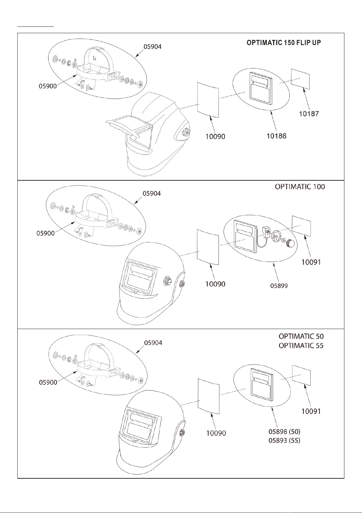
EXPLODED
11

ASISTENCIA TÉCNICA SOLTER
ATENCIÓN AL CLIENTE
Email: solter@solter.com
Todos los clientes propietarios de equipos SOLTER en caso de avería o consulta técnica no duden en
ponerse en contacto con nosotros y nuestro equipo de profesionales atenderá sus consultas de inmediato.
DECLARACIÓN DE CONFORMIDAD
S OLTER soldadura, S.L. NIF: B- 17245127
CTRA. NACIONAL 260, KM 122
17530 CAMPDEVÀNOL (GIRONA) SPAIN
Declaro bajo mi responsabilidad que el producto
Nombre:
OPTIMATIC 150 FLIP UP / OPTIMATIC 50 / OPTIMATIC 55 / OPTIMATIC 100
Al que se refiere esta declaración está en conformidad con la(s) siguiente(s) norma(s) o documento(s)
normativo(s).
EN 175, EN 379
Siguiendo las prescripciones de la(s) Directiva(s)
2006/95/CE (LVD, EMC), 2002/95/EC (ROHS), 2002/96/EC (WEE), 89/686/CEE
Campdevànol a Noviembre de 2020
INFORMACIÓN DE LA GARANTÍA.
Ofrecemos una garantía limitada para este producto contra cualquier defecto de material y mano de obra
durante un período de 12 meses a partir de la fecha de compra por parte del usuario final / consumidor.
Las condiciones de la garantía son las siguientes:
La garantía solo será valida con la presentación de la factura de compra vinculada al número de serie del
equipo. También debe figurar la fecha de compra.
La garantía no cubre defectos por mal uso, instalación incorrecta, modificación o manipulación del producto.
No nos responsabilizamos de daños causados por un mal uso o uso incorrecto del equipo.
La garantía está limitada a la reparación de los componentes defectuosos.
En el caso de que el producto sea reparado o reemplazado, el periodo de garantía seguirá siendo válido para
el periodo restante.
WARRANTY INFORMATION.
We offer a limited warranty for this product against any defects in material and workmanship for a period of 12
months from the date of purchase by the end user / consumer.
The warranty conditions are as follows:
The guarantee will only be valid with the presentation of the purchase invoice linked to the serial number of the
equipment. The date of purchase must also appear.
The warranty does not cover defects due to misuse, incorrect installation, modification or manipulation of the
product.
We are not responsible for damage caused by misuse or incorrect use of the equipment.
The warranty is limited to the repair of defective components.
In the event that the product is repaired or replaced, the warranty period will remain valid for the remaining
period
12
Table of contents
Languages:
Other Solter Welding Accessories manuals


Popular Welding Accessories manuals by other brands


Sealey
Sealey PWH620.V2 Instructions for use

A.C.E. International Company
A.C.E. International Company ArcOne Singles Series manual

Lincoln Electric
Lincoln Electric MINIFLEX K2376-1 Technical specifications

GYS
GYS WELDING BOOTH Assembly & instruction manual

ThermOweld
ThermOweld CX-7 instructions

Sundstrom
Sundstrom SR 592 operation instruction


