ProArc PT-750 User manual
OWNER’S MANUAL
Important:Read these instructions before installing, operating or servicing this product.
MODEL
:
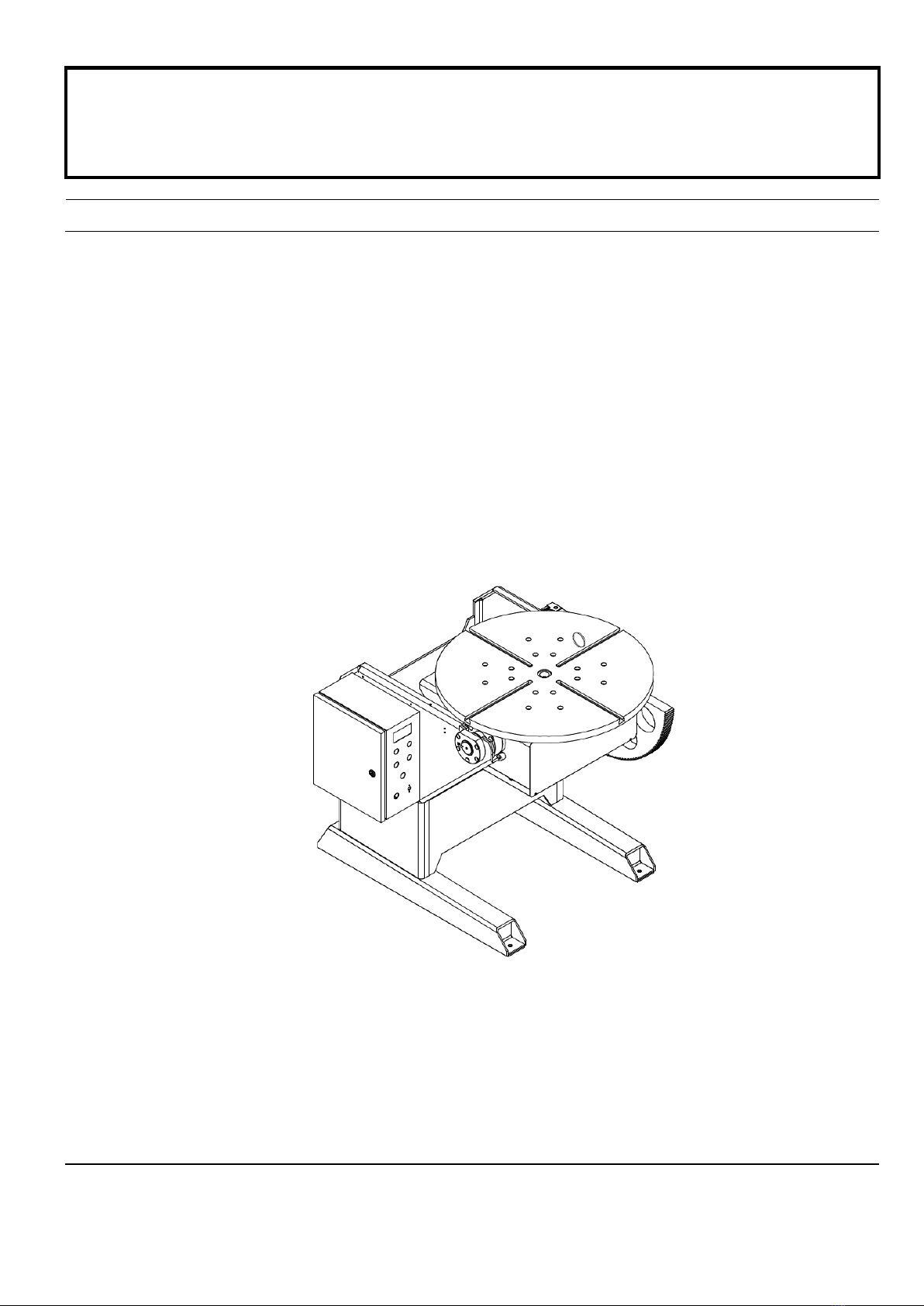
PT–750 / PT–1500
WELDING POSITIONER
Serial Number
:
1307016 ~ and later
Date
:
Aug, 26, 2013
UNITED PROARC CORPORATION
No.3 Gungye 10th Road, Pingjen Industrial Park, Tel No:88634696600
Pingjen City, Taoyuan 324, Taiwan Fax No:88634694499
http://www.proarc.com.tw E-Mail:customerservice@proarc.com.tw
RD-8422E


TABLE OF CONTENTS
Introduction
General information
Maintenance
Operation instruction
Service
Parts list
Diagram
Appendix
Circuit
Revised
Introduction .......................................................................................................i
Safety precautions............................................................................................ii
Limited warranty...............................................................................................iii
1.1 Introduction ................................................................................................1
1.2 Specifications.............................................................................................2
2.1 Maintenance...............................................................................................3
3.1 Operation instruction ..................................................................................4
3.2 Sequence diagram .....................................................................................5
4.1 Trouble shooting guide...............................................................................6
5.1 Part List ‒Machine (PT-750)......................................................................8
5.2 Part List ‒Machine (PT-1500)...................................................................10
5.3 Part List ‒Ground.....................................................................................12
5.4 Part List ‒Control box...............................................................................14
6.1 Control system box....................................................................................16
6.2 Main circuit................................................................................................17
6.3 Remote control circuit................................................................................18
6.4 Inside input / output connect interface.......................................................19
6.5 Input / output connect interface .................................................................22
A:Rotation parameter settings.......................................................................24
B:Tilt parameter settings...............................................................................25
Wiring diagram................................................................................................26
Revision ..........................................................................................................28

i
INTRODUCTION
Read and understand this entire manual regarding the rules for users’
safety before installing, operating, or servicing the equipment.
A procedure, which if not properly followed, may cause injury to the
operator or others in the operating area
Equipment identification
Receipt of equipment
The identification number (specification or part number), model, and serial
number of this unit usually appear on a nameplate attached to the control panel;
record these numbers for future reference.
When you receive the equipment, check it against the shipping documents.
Make sure it is complete and inspect the equipment for possible damage
during shipping. If there is any damage, notify the carrier immediately to file a
claim.
Furnish complete information concerning damage claims or mistakes in
shipment to United ProArc Corporation:No. 3 Gungye 10th Road, Pingjen
Industrial Park, Pingjen City, Taoyuan 324, Taiwan. Include the quipment
identification number along with a description of the parts in question.
Move the equipment to the installation site before uncrating the unit. Use care
to avoid damaging the equipment when using bars, hammers, etc. to uncrate
the unit.
Falling machine due to lifting device failure may cause death or injury.
﹡Lifting device may fail when overloaded.
﹡Avoid sudden jerks, drops or swinging.
﹡Check lifting device components visually for looseness and signs of metal
fatigue.
﹡Before changing any hardware, check grade and size of bolts, and replace
with bolts of equal or higher size and grade. Additional copies of this manual
may be purchase by contacting United ProArc Corporation.
﹡Before operating, be sure to adjust correct input voltage.
WARNING
WARNING
WARNING

ii
SAFETY PRECAUTIONS
Operation and maintenance involve potential hazards. All operators and
personnel should be alerted to possible hazards and precautions should
be taken to prevent possible injury.
Electrical safety
Maintenance
Individual safety
Machine:
﹡Terminate the main power on the external NFB.
﹡
The counter, safety device against excess current and electrical installation, are
compatible with its maximum power and its main voltage.
﹡
The connection, single-phase or three-phase, is possible on a stand compatible
with the plug of its cable link.
﹡
If the cable is connected with the electrical network, the earth, must never be cut by
the protection device against electrical shocks.
Work place:
﹡
Be very careful to avoid contact between metal part and phase conductor and the
neutral of electric network.
﹡
Electrical messes of different electrical machine and apparatus are connected
between themselves and with the terminal of earth neutral wire.
Interventions:
﹡
Before control and repair, see the apparatus is switched off and insulated.
﹡
Connection with fixed installation cable is impossible.
﹡
Switch off by fixed connection is multi-polar (phase and neutral).
﹡
It’s on “Stop” and connection is impossible.
﹡
Some apparatus are provided with starting circuit HT HF (with a plate). Never enter
into the corresponding switch cupboard.
﹡
Only qualified persons are authorized for intervention concerning electrical
installation.
﹡Often check the insulation and connection good state Of apparatus and electrical
accessories: taps, appliance cords, coatings, switch, extension cords, etc.
﹡Maintenance and repair of insulating coatings operations are very important.
﹡
Do repair with a specialist or better replace defective accessories.
﹡
Check regularly the right adjustment and the non-heating of electrical connections.
﹡
The operator must be dressed and protected in relation with his work.
﹡
Avoid contacting metal parts connected or accidentally connected.
﹡Wear leather gloves with gauntlet.
﹡
Safety clothes: gloves, apron, safety shoes protect the operator and his assistants
against burns of hot parts, projections and slag.
WARNING

iii
LIMITED WARRANTY
UNITED PROARC CORPORATION warrants all new equipment to be free from defects in material and
workmanship for a period of one (1) year, provided that the equipment is installed and operated according to
instructions stated in this manual.
UNITED PROARC’s obligation under this warranty policy is expressly limited to the replace or repair, at its
option, of the defected part only. ProArc’s option to repair or replacement of a defected part under this
warranty shall be based on FOB Taiwan basis.
UNITED PROARC CORPORATION shall not be liable for any loss or consequential damage or express
accruing directly or indirectly from the use of equipment covered by this warranty.
This warranty supersedes all previous ProArc warranties and is exclusive with no other guarantees or
warranties expressed or implied.
This warranty excludes the consumable parts that are used in normal operation.

1
1.1 INTRODUCTION
Instruction
Main features
﹡Welding positioned is normally used in the rotating and welding of the pipe or round
work pieces.
﹡It can be applied on all kinds of welding: SMAW, MIG, TIG, Plasma, etc.
﹡It can adopt different fixture to get the welding effects you require.
﹡The table can be tilted for 0~135°, which is convenient for all angles of the pipe
welding or for adjusting welding angles. (It can adopt either manual or electrical
operation.)
﹡The table has a through hole of φ1”, which is convenient for the long pipe welding
or the purge shielding gas.
﹡On the table, there are 4 slots, suitable for all kinds of grippers.
﹡Farthing current: 800amps 100%.
﹡All units are high frequency protected.
2
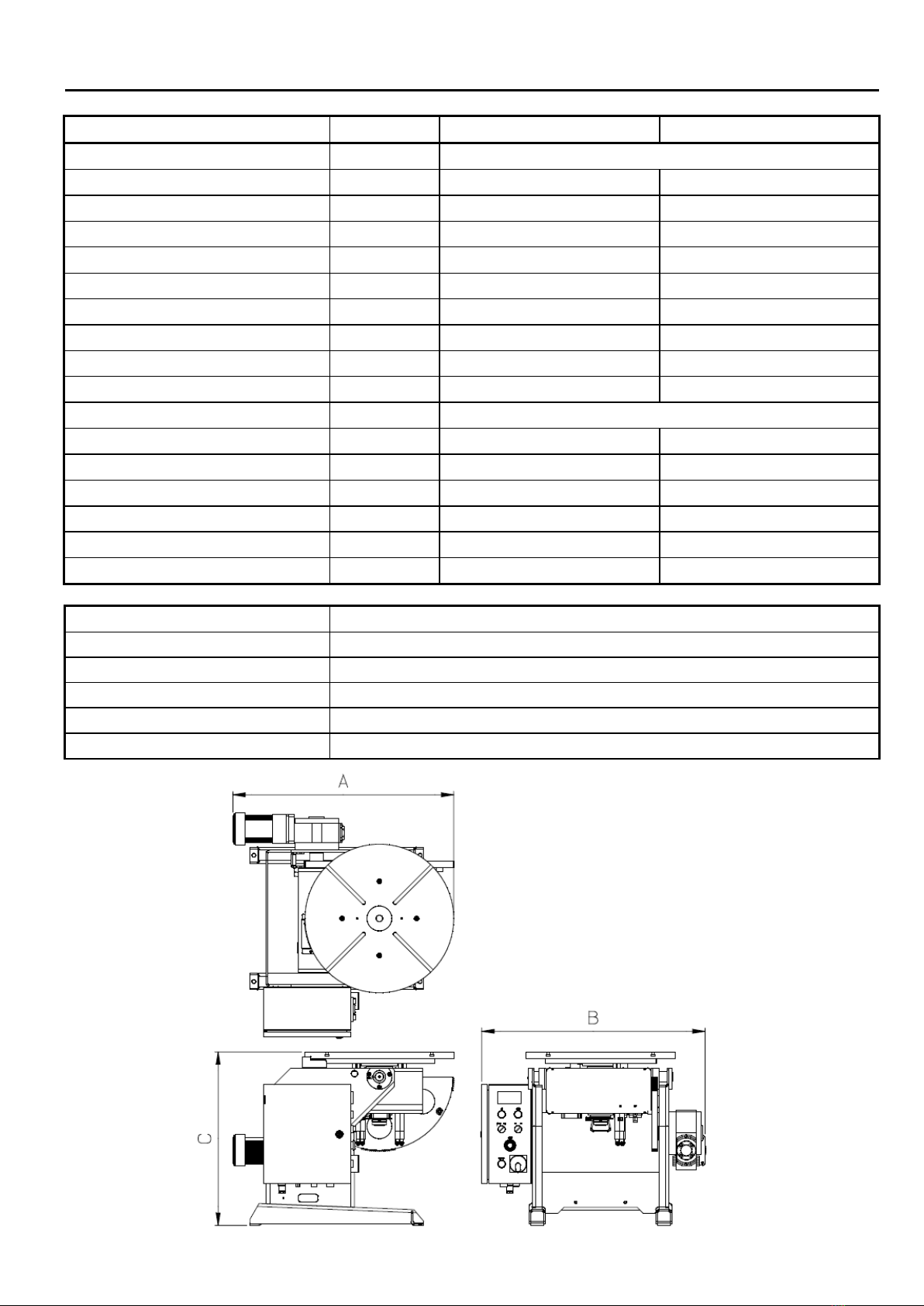
1.2 SPECIFICATION
MODEL
UNIT
PT-750
PT-1500
Power input
1 Phase 220V 50/60Hz
Rated capacity
KVA
1.5
3
NFB capacity
A
6
10
Capacity(Horizontal / Vertical)
kg
750 / 500
1,500
Rated center of gravity
mm
300
300
Rated eccentricity
mm
300
300
Table diameter
mm
600
800
Rotation speed
rpm
0.05~1
0.05~1
Spindle thru hole
mm
25
35
Ear thing
Amp
400
800
Tilt range
deg.
0~135
Tilt speed (135°deg)
sec
45
58
Overall length (A)
mm
900
1,240
Overall width (B)
mm
910
1,190
Overall height (C)
mm
700
990
Center to floor (AD type)
mm
600(600~975) 850(850~1300)
Weight
kg
323
750
Installation location
Altitude 1000M or below , Free from corrosive gas and liquid.
Ambient temperature
0~+40
℃(
non-condensing and not frozen
)
Ambient humidity
Below 90%RH
(
non-condensing
)
Storage temperature
-20~+60
℃(
non-condensing and not frozen
)
Storage humidity
Below 90%RH
(
non-condensing
)
International projection
IP 22

3
2.1 MAINTENANCE
Routine maintenance ﹡After using the machine, make sure to turn off the input main power to prevent
the leakage of the electricity.
﹡To make sure the function of the machine could work well for a long time,
please keep clean all around the machine and the switch from the oil pollution.
﹡To make the machine run normally, the control box, the machine and the table
should be kept clean all the time.
﹡Check regularly the lubrication of the reducer to extend the lifetime of the
machine.
﹡Check cable if damaged or melted due to overheat.
﹡Check the contactor, relay and other connectors if loosen or melted.
﹡Check every limit switch is fixed or loses function.
﹡Give the machine cleaning and the anti-rust maintenance regularly.
﹡Change and refill the lubrication of the worm reducer regularly.
4
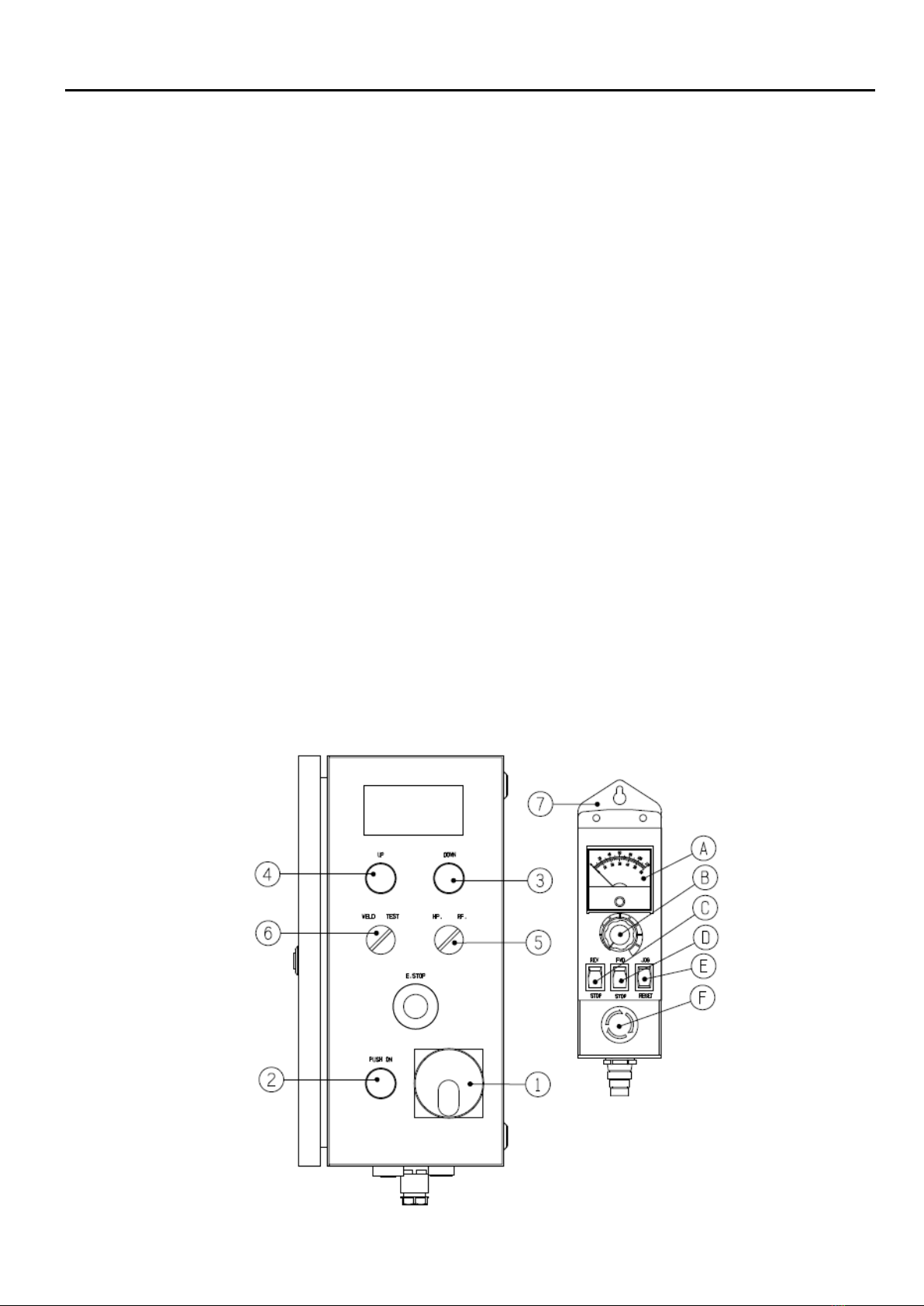
3.1 OPERATION INSTRUCTION
1. Rotary’s power switch:System’s control power switch .
2. “Start” switch (Power):Turn ON the main power switch, press the control power switch ( power light ) to
start operation.
3. Tilt direction switch (Down):Press button to move down direction; release to stop.
4. Tilt direction switch (Up):Press button to move up direction; release to stop.
5. HP / RF switch (H.P / R.F):
a. H.P:the turning speed of rotation table is only controlled by hand pendant,foot switch has rotation /
stop function。
b. R.F:the maximum speed of rotation table is controlled by hand pendant speed knob,the speed of
rotation table can be adjusted accordingly using foot variable speed control。
6. Test / Weld switch (Test / Weld):
Weld:The welding output of JN1 is activated when pressing “Run” button of remote control device.
Test:The welding output of JN1 is always off。
7. Remote control device:
A. Speed meter:Shows the speed data (Hz.)
B. Speed knob:To increase speed, turn clockwise.
To decrease speed, turn counter clockwise.
C. Forward / Reverse:Indicates forward and reverse direction of the table.
Caution
:
[ While turning, please avoid changing direction. ]
D. Run / Stop:Set the “Forward / Reverse” direction followed by pressing the “Run” button to turn the
table continuously. Press “Stop” button to stop the turning.
E. Jog / Reset:While the machine is not in motion, you can adjust to desired position max speed by
pressing “Jog” function. When the inverter driver displays an error message, press
“Reset” to clear the error and reset the system.
F. E-stop button:Press the emergency stop button to terminate the driver circuit.

5
3.2 SEQUENCE DIAGRAM

6
4.1 TROUBLE SHOOTING GUIDE
SYMPTOM POSSIBLE CAUSE/ REMEDY
1. The power indicator light doesn't lit
A. NFB jumps off.
Check main circuit for any disconnection or short.
B. No power input.
Inspect the AC power input voltage.
C. Power supply no DC24V output.
1. Inspect and make sure the switching power supply AC
input voltage is correct.
2. Check / replace the fuse when necessary.
D. Control PCB damaged.
Please refer to symptom no. 2.
E. The indicator light breaks down.
1. Make sure the voltage indicator is DC24V.
2. Check / replace LED when necessary
2. Control PC board indicator ( LED
lamp) doesn’t lit or damaged
A. No AC or DC power input.
Inspect the AC220V/DC24V power input voltage.
B. Fuse burn down.
Check/replace F1 & F2 fuse when necessary.
3. Inverter – no display
A. Inverter has no power input.
Check if magnetic contactor is defective, replace when
necessary.
B. Inverter has power input.
Check if inverter’s digital remote panel is defective, replace
when necessary.
4. Inverter – displays ALM A. Inverter driver displays “ALM” error.
Check display status and refer to inverter driver’s manual
trouble shooting guide.
5. The turntable has no movement
A. Remote control breaks down.
Please refer to symptom No. 7.
B. Foot switch is damaged.
Please refer to symptom No. 8.
C. Failed control PC board.
Please refer to symptom No. 2.
D. Inverter breaks down, no output.
Please refer to symptom Nos. 3 & 4.
E. Failed motor.
Check if there is input power voltage AC220V, refer to
possible cause No 5.F.
F. The reducer is damaged.
Replace a new reducer.

7
4.1 TROUBLE SHOOTING GUIDE
SYMPTOM POSSIBLE CAUSE/ REMEDY
5. The tilt cannot move or over tilt
A. Tilt direction switch breaks down.
Check / replace a new switch.
B. Failed control PC board.
Please refer to symptom No. 2.
C. Inverter breaks down, no output.
Please refer to symptom Nos. 3 & 4.
D. Limit switch breaks down.
(a) Inspect if limit switch contactor is in normal condition,
replace when necessary.
(b) Make sure the dog is in correct position, adjust when
needed.
E. Failed motor.
Check if there is input power voltage AC220V refer to
possible cause No.6.F.
F. The reducer is damaged.
Replace a new reducer.
6. Remote switch has no action or
speed control knob disable
A. Snap switch damaged.
Check / replace the snap switch contactor if necessary.
B. Potentiometer damaged.
Measure the potentiometer resistance (5KΩ), replace a new
one if needed.
C. Indicator not working.
Change the indicator.
7. Foot remote-speed control disable
A. Foot remote control’s limit switch damaged.
(a) Check if the limit switch contactor is in normal condition,
replace when necessary.
(b) Make sure the dog is in correct position, adjust when
needed.
B. Potentiometer damaged.
Measure the potentiometer resistance (5KΩ), replace a new
one if needed.

8
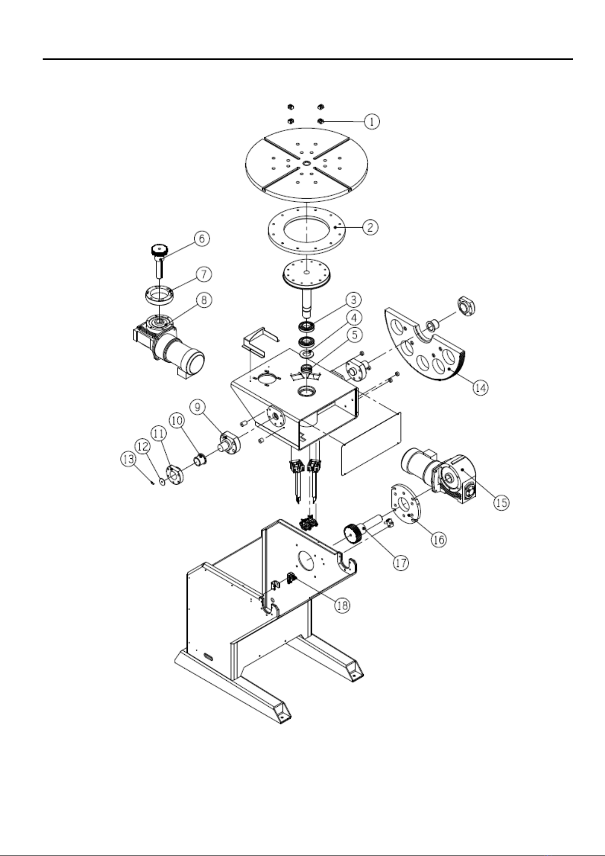
5.1 PARTS LIST – MACHINE ( PT – 750 )
Fig. No. Part No. Description Qty. Remark
1
0127-0002 T – nut 4 M12
2
5014-1020000-10 Rotation–Gear 1
3
*
0305-1001 Bearing 1
4
0305-0801 Bearing 1
5
5014-1030000-20 Rotation – Drive pinion 1
6
*
0353-0102 Worm reducer 1
*
0350-0023 Motor reducer 1
7
5014-1090000-10 Home limited bracket 1
8
0120-0004 Precision lock – Nut 1
9
5014-2160000-20 Tilting – Main shaft 1
10
5014-2030000-20 Tilting shaft 1
11
*
0332-3501 Self lubricating bearing 2
12
*
5014-2040000-20 Tilting – Bearing housing 2
13
5015-2100000-10 Angle scale 1
14
5015-2110000-20 Indicator 1
15
*
0353-0103 Worm reducer 1
*
0350-0027 Motor reducer with brake 1
16
5014-2020000-20 Drive pinion 1
17
*
3242-2002 Limit switch 2
*Recommended spare parts
**Option

9
5.1 PARTS LIST – MACHINE ( PT – 750 )

10
5.2 PARTS LIST – MACHINE( PT – 1500 )
Fig. No. Part No. Description Qty. Remark
1 * 0127-0001 T – Nut 4 M16
2 5015-1020000-10 Rotation – Gear 1
3 * 0305-1101 Bearing 2
4 5015-1060000-10 Rotation – Spacer 1
5 0120-0005 Precision lock – Nut 1
6 5015-1030000-20 Rotation – drive pinion 1
7 5015-1070000-10 Rotation – Reducer flange 1
8
*
0350-0028 Motor reducer 1
*
0353-0103 Worm reducer 1
9 5015-2030000-10 Tilting – Main shaft 1
10 5015-2050000-10 Self lubricating bearing 2
11 5015-2040000-10 Tilting – bearing housing 2
12 5015-2100000-10 Angle scale 1
13 5014-2250000-21 Indicator 1
14 5015-2010000-20 Tilting – Gear 1
15 * 0353-0140 Worm reducer 1
* 0350-0001 Motor reducer with brake 1
16 5015-2060000-20 Tilting – Reducer flange 1
17 5015-2020000-20 Tilting – drive pinion 1
18 * 3241-2002 Limit switch 2
* Recommended spare parts
** Option
11
5.2 PARTS LIST – MACHINE( PT – 1500 )

12
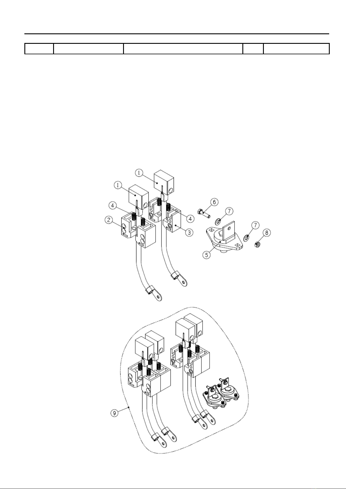
5.3 PARTS LIST ‒GROUND (PT-750)
Fig. No.
Part No.
Description
Qty.
Remark
1
*
5010-2050102-10 Carbon brush 2
2
*
5010-2040100-20
PE plastic body
2
3
*
0144-0028 Spring 4
4
0106-0803
Hex cap screws (cupper)
1
5
0121-0804 Washer (cupper) 2
6
*
4000-039046
Terminal
1
7
0123-0802 Nut (cupper) 1
8
*
5015-3080020-21 Ground 1st
*Recommended spare parts
** Option
13
5.3 PARTS LIST ‒GROUND (PT-1500)
Fig. No.
Part No.
Description
Qty.
Remark
1
*
5010-2050102-10
Carbon brush
4
2
*
5010-2040400-10 PE plastic body 2
3
5010-2040500-10
PE plastic body
2
4
*
0144-0028
Spring
8
5
*
4000-039046
Terminal
2
6
0106-0803 Hex cap screws (cupper) 2
7
0121-0804
Washer (cupper)
4
8
0123-0802
Nut (cupper)
2
9
*
5015-3080000-21
Ground
1st
*Recommended spare parts
** Option

14
5.4 PARTS LIST – CONTROL BOX
Fig. No.
Part No.
Description
Qty.
Remark
1
3221-2003
No Fuse breaker
1
NFB (PT-750)
2
3323-0002 Power supply 1 PS
3
*
6652-1121 PC Board 1 PCB
4
3332-1201
EMI filter
1
RF (PT-750/1500)
5
*
3224-1005
Magnetic contactor
1
MC
6
**
3021-2002 Inverter 1 INV2 (PT-750)
**
3021-2005 Inverter 1 INV2 (PT-1500)
7
**
3021-2001
Inverter
1
INV1 (PT-750)
**
3021-2004
Inverter
1
INV1 (PT-1500)
8
3061-1006 Meter 1
9
3214-4003 Push button 1 DN
10
3214-4005
Push button
1
UP
11
3211-4105
Select button
2
SW1,SW2
12
3214-2002 ES Push button 1
3214-1005 Contact 1
13
3214-4006
Push button
1
PB1
14
3216-1003
Rotaries switch
1
CS1
15
3122-7002 Female plug 1 JN4
16
3122-4003 Female socket 2 JN2/JN3
17
3124-2005
Male socket 4Pin
1
18
3534-3005
Power cable gland
1
P1
19
3122-4004 Female socket 10Pin 1 JN5
20
3123-3003 Female plug 4Pin 1
3124-3003
Male socket 4Pin
1
21
3242-1001
Foot switch latch ass'y
1st
3M
21-1
3121-6002 Male plug 1
**
3455-0002 Shielded cable M 3M or 7.5M
22
3023-0002
Pendant Inverter
1st
Remote Control
22-1
**
3457-4006
Pendant inverter cable
1st
3M
**
3457-4007 Pendant inverter cable 1st 7.5M
* Recommended spare parts
** Option
This manual suits for next models
1
Table of contents
Other ProArc Welding Accessories manuals


Popular Welding Accessories manuals by other brands


Miller
Miller Classic Clearlight owner's manual

Nederma
Nederma 10500133 user manual

Inverter Fusion
Inverter Fusion Fusion MultiClean operating instructions

ESAB
ESAB Eye-Tech 10-12 Select instructions

jbc
jbc SB03CC instruction manual

COWLEY INDUSTRIES
COWLEY INDUSTRIES LM05 Installation and operating instructions


