Solter Hellmet Devil User manual

MI03170-07
07/2022

1
INTRODUCCIÓN
Agradecemos su deferencia hacia nuestra marca y esperamos le sea de gran utilidad la pantalla de soldadura que
acaba de adquirir. El presente manual de instrucciones contiene las advertencias necesarias para una correcta
utilización dentro de las máximas condiciones de seguridad para el operario. Los filtros de soldadura SOLTER deben
ser empleados por personal experto que conozca y comprenda los riesgos involucrados en la utilización de los
mismos. En caso de incomprensión o duda sobre este manual le rogamos que se ponga en contacto con nosotros. La
manipulación del filtro de soldadura conlleva un peligro importante de lesión. Rogamos se abstenga de efectuar
cualquier manipulación en el filtro o casco. Sólo personal técnicamente preparado puede realizarlo.
SOLTER Soldadura S.L., declina toda responsabilidad por prácticas negligentes en la utilización y/o manipulación.
Este manual debe adjuntarse y conservarse con el modelo de filtro adquirido. Estos filtros están diseñados y
aprobados de acuerdo con la Norma Europea EN 379.
Es responsabilidad de las personas que los utilicen y reparen que el producto no deje de cumplir los requisitos de las
normas mencionadas.
ANTES DE EMPEZAR A SOLDAR
Antes de usar cualquiera de los filtros de soldadura asegúrese de retirar los films de protección correspondientes,
mantenga limpia el área de visión y la parte frontal del filtro ya que ahí se encuentran los sensores que se ocupan del
oscurecimiento del filtro.
Inspeccionar todas las partes operativas antes de usar la pantalla y comprobar que no existen signos de deterioro.
Cualquier parte deteriorada debe sustituirse inmediatamente antes de su utilización. Verificar el funcionamiento del
filtro antes de cada uso.
Asegúrese también de que la sujeción del mismo a la pantalla de protección es correcta para evitar que se pueda
desprender ante cualquier impacto pudiendo provocar daños personales al usuario.
En caso de que el DIN de oscurecimiento del filtro sea regulable ajústelo correctamente antes de cualquier aplicación,
para saber el grado adecuado para todas las aplicaciones consulte el apartado TABLA DE ELECCIÓN DE FILTROS
SEGÚN APLICACIÓN del manual de la pantalla de protección.
CARACTERÍSTICAS TÉCNICAS
PROPIEDADES
DEVIL / GUARDIAN / WELDER / JOB / ARMY /
STREAMPUNK / R-10
R-20 DI
R-10XL
Área de visión
100 x 60 mm
100 x 53 mm
100 x 100 mm
Policarbonato delantero
115 x 104 mm
117 x 136 mm
Clase Óptica
1/1/1/1
Sensores de arco
4
Oscurecimiento variable
Si (Externo)
Rango Oscurecimiento
DIN 5-8 / 9-13 (Externo)
Modo Amolado
DIN 4 (Externo)
Sensibilidad Variable
Si (Externo)
Tiempo de reacción
(claro>oscuro)
1/30000 s
Tiempo conmutación
(oscuro>claro)
0,1 – 1,0 s
Protección UV / IR
DIN 16
Tipo de energía
Panel Solar y Batería reemplazable CR2450 / CR2032 para R-20
Peso
0,57 Kg.
0,53 Kg.
0,66 Kg.
2

Marcado CE
Todos los filtros vienen marcados tal y como indica el certificado CE de cada modelo. En este marcaje se especifica
con el primer número el grado de protección DIN que tiene el filtro cuando está en estado abierto (claro), el siguiente
número indica el grado DIN en estado cerrado (oscuro) indicando el grado mínimo y el máximo. El símbolo que hay
entre los dos números nos indica si el ajuste del grado DIN es manual o automático. Los tres siguientes números nos
indican el tipo de óptica, la dispersión de luz del filtro y la homogeneidad de la visión del filtro según normativa.
Los tres números siguientes indican la Normativa Europea con la que cumple el filtro.
AJUSTES DE LOS FILTROS ANALÓGICOS
1 - Placa Solar
2 - Normativa
3 - Modo Soldadura
4 - Oscurecimiento
5 - Pila intercambiable CR2450
6 - Ajuste retraso
7 - Ajuste sensibilidad
8 - Sensores Arco
9 - Área de visión
3

Oscurecimiento, grado DIN.
El ajuste del grado DIN dependerá de la aplicación de la cual nos
queramos proteger y de su potencia. El grado DIN es el grado de
oscuridad del filtro durante el proceso de soldadura. Ajustar con la rueda
entre 9 y 13.
Sensibilidad
Ajusta la intensidad de luz necesaria para que el filtro pase de estado abierto a estado cerrado (oscuro). La posición
MIN la sensibilidad a la luz es baja, en posición MAX la sensibilidad a la luz es alta.
Retraso
Ajusta el tiempo que tarda el filtro en volver a estado abierto (claro) original una vez finalizado el proceso de
soldadura. Para los modelos HELLMET la posición MIN el retraso es de 0,1s, en posición MAX el retraso es de 1s.
4

AJUSTES DEL FILTRO DIGITAL
SET. Para ajustar los parámetros de sensibilidad, oscurecimiento y retraso, se debe pulsar SET, seleccionar el
parámetro deseado y ajustar el valor requerido con las teclas + y -.
MODE. Pulsador para ajustar el modo entre soldadura, corte y amolado.
Pulsadores + y -. Utilizador para aumentar o disminuir los valores de sensibilidad, oscurecimiento y retraso.
Funciones extras de los filtros
Algunos filtros permiten operar en varios modos de funcionamiento: Soldadura, amolado y corte por plasma.
Amolado: Se usa para aplicaciones de amolado de materiales. En este modo, la función de oscurecimiento está
apagada. La protección está en estado claro, lo que permite tener una visión clara con la seguridad de que la
máscara protegerá la cara de cualquier posible daño.
Con la finalidad de ahorrar batería, en los modelos analógicos, seleccione el modo amolado siempre que no esté
soldando.
El modo amolado está pensado para realizar trabajos de amolado, no de soldadura.
Antes de volver a soldar asegúrese de volver a dejar la perilla en la posición de soldadura.
Soldadura: Se usa para la mayoría de las aplicaciones de soldadura. En este modo, la función de oscurecimiento
5
está encendida. Seleccione el nivel de protección, el tiempo de retardo y el nivel de sensibilidad adecuado.
Corte por plasma: Utilizado para cortar con equipos de plasma, se puede regular el oscurecimiento entre 5 y 8.
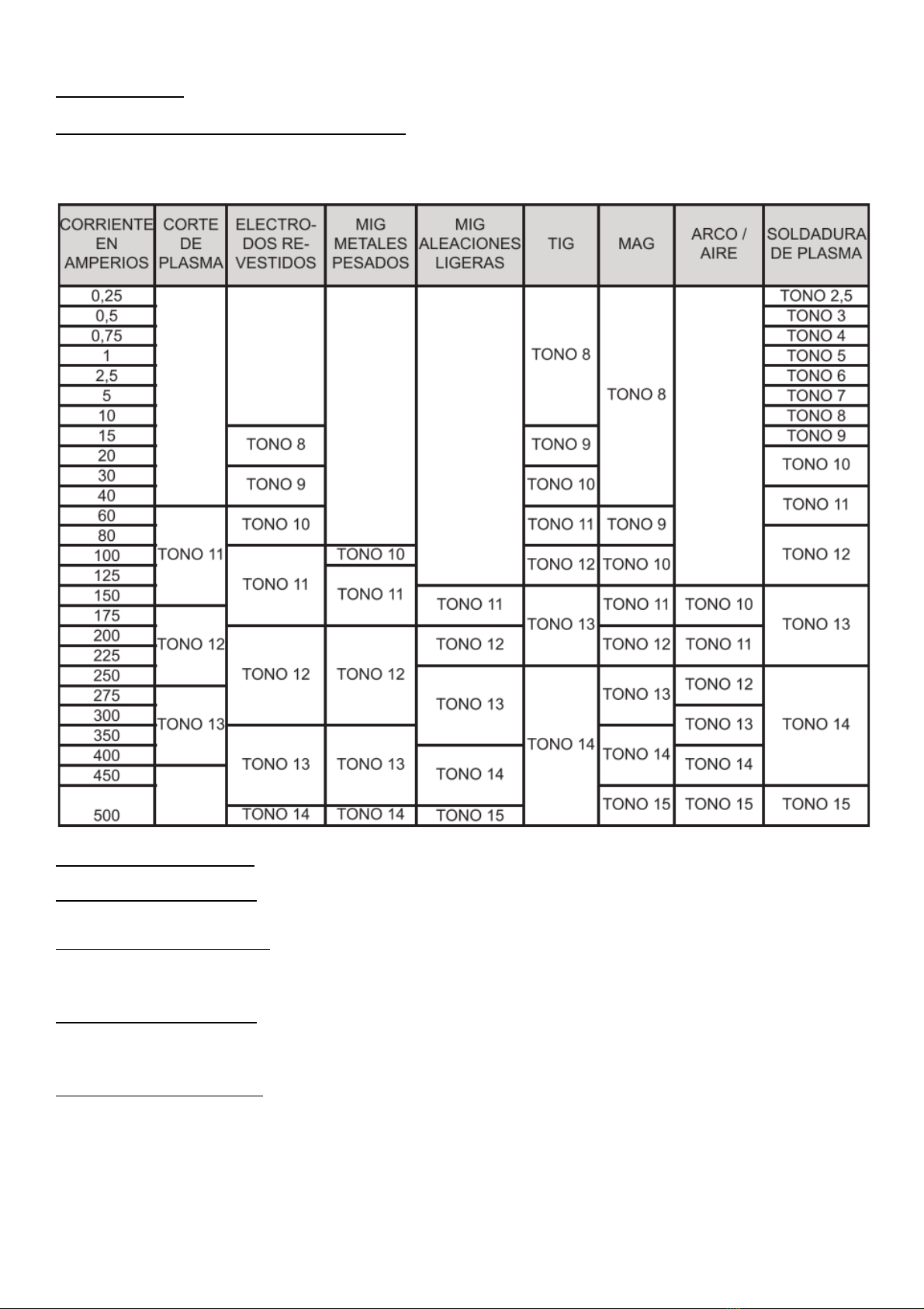
AJUSTE DEL GRADO DE PROTECCIÓN
En caso de disponer de un filtro con DIN regulable, ajustar el grado según la aplicación de la cual nos queremos
proteger. Ver la siguiente tabla.
AJUSTES DEL ARNÉS
Altura del arnés (Posición W)
Ajuste el arnés en la profundidad adecuada a su cabeza para asegurar un equilibrio correcto y estable.
Estrechar el arnés (Posición Y)
Pulse el botón de ajuste de la parte trasera del arnés y gire hacia la derecha o la izquierda hasta la posición
adecuada.
Ajustar distancia (Posición Z)
Ajuste la distancia entre la cara y la lente aflojando por igual las dos tuercas exteriores y presione hacia dentro para
liberarlo de las ranuras de ajuste.
Ajuste del ángulo (Posición X)
Cuatro pernos en el lado derecho superior del arnés proporcionan un ajuste para la futura inclinación del casco. Para
ajustar, afloje la perilla de ajuste del lado derecho, a continuación, levante la pestaña del brazo de control y muévalo a
la posición deseada. Finalmente, vuelva a apretar la perilla de ajuste.
6

POSIBLES ANOMALÍAS
PROBLEMA
POSIBLES SOLUCIONES
Oscurecido irregular del filtro
La cinta de ajuste ha sido posicionada incorrectamente o el ángulo del
casco respecto a nuestra área de visión no es el adecuado.
El filtro no se oscurece o parpadea
La batería CR2450 o CR2032 (modelo digital) está agotada. Sustituyala.
El filtro protector frontal está dañado o en mal estado.
Respuesta del filtro lenta
Los sensores están sucios.
La corriente de soldadura es demasiado baja.
La temperatura de trabajo es demasiado baja.
Visión insuficiente
Los filtros protectores frontal o posterior están sucios.
Índice de protección incorrecto.
Insuficiente luz en el ambiente de trabajo.
DESPIECE
POS.
CÓDIGO
JOB
GUARDIAN
DEVIL
WELDER
STEAMPUNK
ARMY
R-10
R-20 DI
R-10XL
1
10088
10086
2
05861
10188
30052
3
10089
10198
10087
4
05863
05863
5
05864
30051
6
06770
06771
06772
06773
10300
10074
10044
10170
10075
7

INTRODUCTION
We appreciate your deference to our brand and we hope the welding helmet you have just purchased will be of great
use to you. This instruction manual contains the necessary warnings for correct use within the maximum safety
conditions for the operator. SOLTER welding filters must be used by expert personnel who know and understand the
risks involved in using them. In case of misunderstanding or doubts about this manual, please contact us. Handling
the weld filter carries a significant risk of injury. Please refrain from doing any manipulation on the filter or helmet. Only
technically trained personnel can do it.
SOLTER Welding SL, declines all responsibility for negligent practices in use and / or handling. This manual should be
attached and kept with the filter model purchased. These filters are designed and approved in accordance with
European Standard EN 379.
It is the responsibility of the people who use and repair them that the product does not fail to meet the requirements of
the aforementioned standards.
BEFORE STARTING TO WELD
Before using any of the welding filters be sure to remove the corresponding protection films, keep the viewing area
and the front part of the filter clean since there are the sensors that take care of the filter darkening.
Inspect all operating parts before using the display and check for signs of deterioration. Any damaged part must be
replaced immediately before use. Check the operation of the filter before each use.
Also make sure that the attachment to the protection screen is correct to prevent it from detaching in the event of any
impact, which could cause personal injury to the user.
If the filter darkening DIN is adjustable, adjust it correctly before any application. To find out the appropriate degree for
all applications, consult the section FILTER CHOICE CHART ACCORDING TO APPLICATION of the protection
screen manual.
TECHNICAL CHARACTERISTICS
PROPERTIES
DEVIL / GUARDIAN / WELDER / JOB / ARMY /
STEAMPUNK / R-10
R-20 DI
R-10XL
Viewing area
100 x 60 mm
100 x 53 mm
100 x 100 mm
Front
polycarbonate 115 x 104 mm
117 x 136 mm
Optical class
1/1/1/1 Arc
sensors
4
Dimming variable
Yes (External)
Darkening range
DIN 5-8 / 9-13 (External)
Grinding mode
DIN 4 (External)
Sensitivity Variable
Yes (External)
Reaction time (light>
dark)
1/30000 s
Switching time (dark>
light)
0.1 - 1.0 s
UV / IR protection
DIN 16
Type of energy
Solar panel and replaceable battery CR2450 / CR2032 for R-20
Weight
0,57 Kg.
0,53 Kg.
0,66 Kg.
CE marking
All filters are marked as indicated by the CE certificate of each model. In this marking, the first number specifies the
degree of DIN protection that the filter has when it is in the open state (clear), the next number indicates the DIN
degree in the closed state (dark) indicating the minimum and maximum degree. The symbol between the two numbers
tells us if the DIN degree setting is manual or automatic. The next three numbers indicate the type of optics, the filter's
8

light dispersion and the uniformity of the filter's vision according to regulations.
The next three numbers indicate the European Regulation with which the filter complies.
ADJUSTMENTS OF THE ANALOG FILTERS
1 - Solar
2 - Regulations
3 - Welding Mode
4 - Darkening (DIN)
5 - CR2450 interchangeable battery
6 - Delay adjustment
7 - Sensitivity adjustment
8 - Arc sensors
9 -viewing area
Darkening, DIN grade.
The DIN degree setting will depend on the application from which we want to
protect and its power. DIN grade is the degree of darkness of the filter during
the welding process. Adjust with the wheel between 9 and 13.
Sensitivity
Adjusts the intensity of light necessary for the filter to go from the open state to the closed state (dark). In the MIN
position the sensitivity to light is low, in the MAX position the sensitivity to light is high.
9

Delay
Adjusts the time it takes for the filter to return to the original open (clear) state after the welding process is complete.
For HELLMET models the MIN position the delay is 0.1s, in the MAX position the delay is 1s.
DIGITAL FILTER SETTINGS
SET. To adjust the sensitivity, darkening and delay parameters, press SET, select the desired parameter and adjust
the required value with the + and - keys.
MODE. Push button to adjust the mode between welding, cutting and grinding.
+ And - buttons. User to increase or decrease sensitivity, darkening and delay values.
Extra functions of the filters
Some filters allow it to operate in various operating modes: welding, grinding and plasma cutting.
Grinding: Used for material grinding applications. In this mode, the dimming function is off. The protection is in a clear
state, allowing you to have a clear view with the assurance that the mask will protect your face from any possible
damage.
In order to save battery life, on analog models, select grinding mode whenever you are not welding.
Grind mode is intended for grinding work, not welding.
10

Before re-welding be sure to return the knob to the welding position.
Welding: Used for most welding applications. In this mode, the dimming function is on. Select the protection level,
delay time, and appropriate sensitivity level.
Plasma cutting: Used to cut with plasma equipment, the darkening can be adjusted between 5 and 8.
ADJUSTING THE DEGREE OF PROTECTION
In case of having a filter with adjustable DIN, adjust the degree according to the application from which we want to
protect ourselves . See the following table.
HARNESS ADJUSTMENTS
Harness Height (Position W)
Adjust the harness to the appropriate depth for your head to ensure correct and stable balance.
Tighten the harness (Position Y)
Press the adjustment button on the back of the harness and turn it to the right or left to the appropriate position.
Adjust Distance (Z Position)
Adjust the distance between the face and the lens by loosening the two outer nuts equally and press inward to release
it from the adjustment slots.
Angle Adjustment (X Position)
Four bolts on the upper right side of the harness provide an adjustment for future helmet lean. To adjust, loosen the
adjustment knob on the right side, then lift the tab on the control arm and move it to the desired position. Finally,
retighten the adjustment knob.
11

POSSIBLE ANOMALIES
PROBLEM
POSSIBLE SOLUTIONS
Irregular darkening of the filter
The adjustment strap has been incorrectly positioned or the angle of the
helmet with respect to our vision area is not adequate.
Filter does not darken or flicker
The CR2450 or CR2032 (digital model) battery is exhausted. Replace it.
The front protective filter is damaged or in poor condition.
Slow filter response
Sensors are dirty.
The welding current is too low.
The working temperature is too low.
Insufficient vision
The front or rear protective filters are dirty.
Wrong protection index.
Insufficient light in the work environment.
EXPLODED VIEW
POS.
CÓDIGO
JOB
GUARDIAN
DEVIL
WELDER
ARMY
STEAMPUNK
R-10
R-20DI
R-10XL
1
10088
10086
2
05861
10188
30052
3
10089
10198
10087
4
05863
05863
5
05864
30051
6
06770
06771
06772
06773
10074
10300
10044
10170
10075
12
ASISTENCIA TÉCNICA SOLTER
ATENCIÓN AL CLIENTE
Email: solter@solter.com
Todos los clientes propietarios de equipos SOLTER en caso de avería o consulta técnica no duden en
ponerse en contacto con nosotros y nuestro equipo de profesionales atenderá sus consultas de inmediato.
DECLARACIÓN DE CONFORMIDAD
S OLTER soldadura, S.L. NIF: B- 17245127
Camí de la Creu, 25
17530 CAMPDEVÀNOL (GIRONA) SPAIN
Declaro bajo mi responsabilidad que el producto
Nombre:
HELLMET DEVIL / GUARDIAN / WELDER / JOB / ARMY / STEAMPUNK / R-10 / R-10XL / R20 DI
Al que se refiere esta declaración está en conformidad con la(s) siguiente(s) norma(s) o documento(s)
normativo(s).
EN 175, EN 379
Siguiendo las prescripciones de la(s) Directiva(s)
2006/95/CE (LVD, EMC), 2002/95/EC (ROHS), 2002/96/EC (WEE), 89/686/CEE
Campdevànol a Julio de 2022
INFORMACIÓN DE LA GARANTÍA.
Ofrecemos una garantía limitada para este producto contra cualquier defecto de material y mano de obra
durante un período de 12 meses a partir de la fecha de compra por parte del usuario final / consumidor.
Las condiciones de la garantía son las siguientes:
La garantía solo será valida con la presentación de la factura de compra vinculada al número de serie del
equipo. También debe figurar la fecha de compra.
La garantía no cubre defectos por mal uso, instalación incorrecta, modificación o manipulación del
producto.
No nos responsabilizamos de daños causados por un mal uso o uso incorrecto del equipo.
La garantía está limitada a la reparación de los componentes defectuosos.
En el caso de que el producto sea reparado o reemplazado, el periodo de garantía seguirá siendo válido
para el periodo restante.
WARRANTY INFORMATION.
We offer a limited warranty for this product against any defects in material and workmanship for a period of
12 months from the date of purchase by the end user / consumer.
The warranty conditions are as follows:
The guarantee will only be valid with the presentation of the purchase invoice linked to the serial number of
the equipment. The date of purchase must also appear.
The warranty does not cover defects due to misuse, incorrect installation, modification or manipulation of
the product.
We are not responsible for damage caused by misuse or incorrect use of the equipment.
The warranty is limited to the repair of defective components.
In the event that the product is repaired or replaced, the warranty period will remain valid for the remaining
period
13
This manual suits for next models
8
Table of contents
Languages:
Other Solter Welding Accessories manuals


