Solton DX4 User manual

www.solton-acoustic.de
ENGLISH
USER MANUAL
A PRODUCT OF SOLTON ACOUSTIC GERMANY

Contents.................................................................................1
Control elements.......................................................................4
Rear panel features introduction ...............................................5/6
Audio input and output connections ..........................................7
Stereo Mode........... ....................................................................8
Bridge Mode................................................................................9
...............................9
Important note......................................................................................2/3
.
Professional Power Amplifier Specifications
1
Contents
2
CAUTION
RISK OF ELECTRIC SHOCK
DO NOT OPEN
SAFE GUARDS
Electrical energy can perform many useful functions. This unit has been engineered and
manufactured to assure your personal safety .Improper use can result in potential electrical
Shock or fire hazards .In order not to defeat the safeguards , observe the following precautions
for its installation , use and servicing.
WARNING: TO PREVENT FIRE OR ELECTRIC SHOCK, DO NOT EXPOSE THIS
EQUIPMENT TO RAIN OR MOISTURE.
CAUTION
RISK OF ELECTRIC SHOCK:
OPEN ONLY IF QUALIFIED
AS SERVICE PERSONNEL
Explanation of Graphical Symbols
WARNING NOTICES
IMPORTANT NOTE
ATTENTION: This unit must be protected from damp because of the risk of fire and the
possibility of electric shocks.
1. Make sure that you have the correct mains voltage. Only operate the unit at the mains
voltage marked on the rear panel.
2. Make sure that nothing especially no metal objects are inserted into the device. This
could result in electric shock or malfunction.
3 . lf the unit is subjected to extreme fluctuations of temperature e.g.On being transported
from outside into a heated room,condensation can form.The unit should not be used until
it has reached room temperature.
4. In the event of water or any other fluid being accidentally spilt on the unit switch the
unit off immediately and send it to a qualified service workshop for inspection.
5. Make sure that the unit is always well ventilated and never exposed to direct sunlight
6. Do not use sprays to clean the unit as they have a detrimental effect on the unit and could
ignite suddenly.
7. The machine use single power switch, please cut off the power before fix.
8. Please do not put the cup, vessel of flower or container above the machine, In case the
leak out water then cause the leakage current off the machine.
Important Note
User responsibility
1. Mains connection grounding
Your amplifier must be connected to a
grounded socket outlet.
2. Speaker output hazard
Power amplifiers are capable of producing
hazardous output voltages. To avoid electrical
shock, do not touch any exposed speaker wiring
while the amplifier is operating. The external wiring
connected to the speaker terminals shall be installed
by a qualified instructed person or ready-made leads
or cords of appropriate capacity shall be used.
Astheamplifieroutputsproducehighvoltage,do
not connect or disconnectspeaker cables when
the mains power is on.Also, attach the safety cover
on the speaker terminals for safe operation and to
comply with electrical product approvals.
3. Radio interference
This product uses radio
frequency energy and if not used or installed in
accordance with these operating instructions, may
cause interference to other equipment, such as radio
receivers. However, there is no guarantee that
Interference will not occur in a particular installation.
If this equipment does cause harmful interference
toradioortelevisionreception,whichcanbedetermined
by turning the equipment on and off, the user
is encouraged to try to correct the interference by
one or more of the following measures:
Reorient or relocate the antenna.
Increase the separation between the equipment
and receiver.
Connect the equipment to an outlet on a circuit
different from that to which the receiver is
CheckiftheaffectedunitcomplieswiththeEMC
limits forimmunity,(CE-labeled).Ifnot,address
theproblemwiththemanufacturerorsupplier.
AllelectricalproductssoldintheECmustbeappr-
ovedforimmunityagainstelectromagneticfields,
highvoltageflashes,andradiointerference.
ConsultthedealeroranexperiencedRadio/TV
technicianforhelp.
WARNING
If you are not 100% confident of your
Competence to replace the mains plug, engage
Qualified personnel to do the job.
Once a suitable AC supply is connected, the
amplifier can be turned on using the front panel
power switch. The amplifier then goes through a
soft-start sequence as it self-checks its circuits. The
fans will blow at high speed before dropping to idle,
and the -power LED -will illuminate.
Inrush poweris controlled and limited during -softstart,
enabling multiple amplifiers to be powered up
Simultaneously.
Grounding
There is no ground lift switch or terminal on the
amplifiers. The signal ground is always floating,
via a resistor, to chassis and therefore the
grounding system is automatic.
In the interests of safety, never disconnect the earth
(Ground) pin on the AC power cord.
Use balanced input connections to avoid hum and
Interference.
The amplifier uses a forced-air cooling system with
Air flow from front to rear, maintaining a low operating
temperature within defined limits.
Your amplifier is very powerful and can be
potentiallydangeroustobothloudspeakersand
humans alike. Many loudspeakers can be easily
damagedordestroyedbyoverpoweringthem.Always
check the speaker's continuous and peak power
capabilities.Although the amplifier's attenuators can
be used toreduce theoverallgain,anincrease ofthe
input signal can result in full output power, which
may causedamagetoconnectedspeakers.
4. Speaker damage
5 .Maintenance
Forsafeandreliableoperation,thedustcovers behind
thefrontpanelshould be cleanedregularly.If thedust
filters are not maintained there will be safety risks.
For example the unit can ignite the dust and a fire
will occur due to high internal temperatures. There
is also a risk that the unit will malfunction since it is
dependent on constant airflow from front to rear. If
thedustfiltersarenotcleanandtheunitmalfunctions,
any resultant problems will not be covered by
the warranty.
3

F ront panel
The front panel LED area includes the following indicators per channel:
1. LEVEL CONTROL
Calibrated detente potentiometers to alter the total gain of the power amplifier . In order to avoid
distortions in mixing consoles upstream , these controls should normally be positioned between 0 and
10 . The calibrated markings show the additional attenuation directly.
2.MUTE LED
MUTE - Au protection under mute position.
3.Clip/limit indicator
This indicator signals if the amplifier output is clipping or limiting. It has two different indication states:
If the clip limiter is not engaged, it has an increased time constant, and it illuminates for a longer
Period.
6. TEMP
This LED lights up if the limiter has been activated and the power amplifier is being operated at the
clip level .If the LED flashes briefly ,this is not a cause for concern. If this LED is lit permanently ,the
volume should be reduced to avoid overload damages to the connected loudspeaker systems.
7.VHF
VHF-Very High Frequency protection active (output muted)(Yellow constant)
9.POWER Switch
Turn the unit power on or off
4.SIG / HI-IMP LED
Green SIGNAL Indicates output signal levels in normal operating range
5.ACLIVE LED
Thes Led lights up when the unit is powered.
Hi-Imp - High-impedance/open load detected (Orange)
8.CPL LED
CPL - (Orange constant with output muted): Low impedance / short circuit detection fault
Control elements
4
1
2
3
4
5
6
7
8
9
If the Clip limiter is engaged, It has a short time constant and it illuminates briefly.
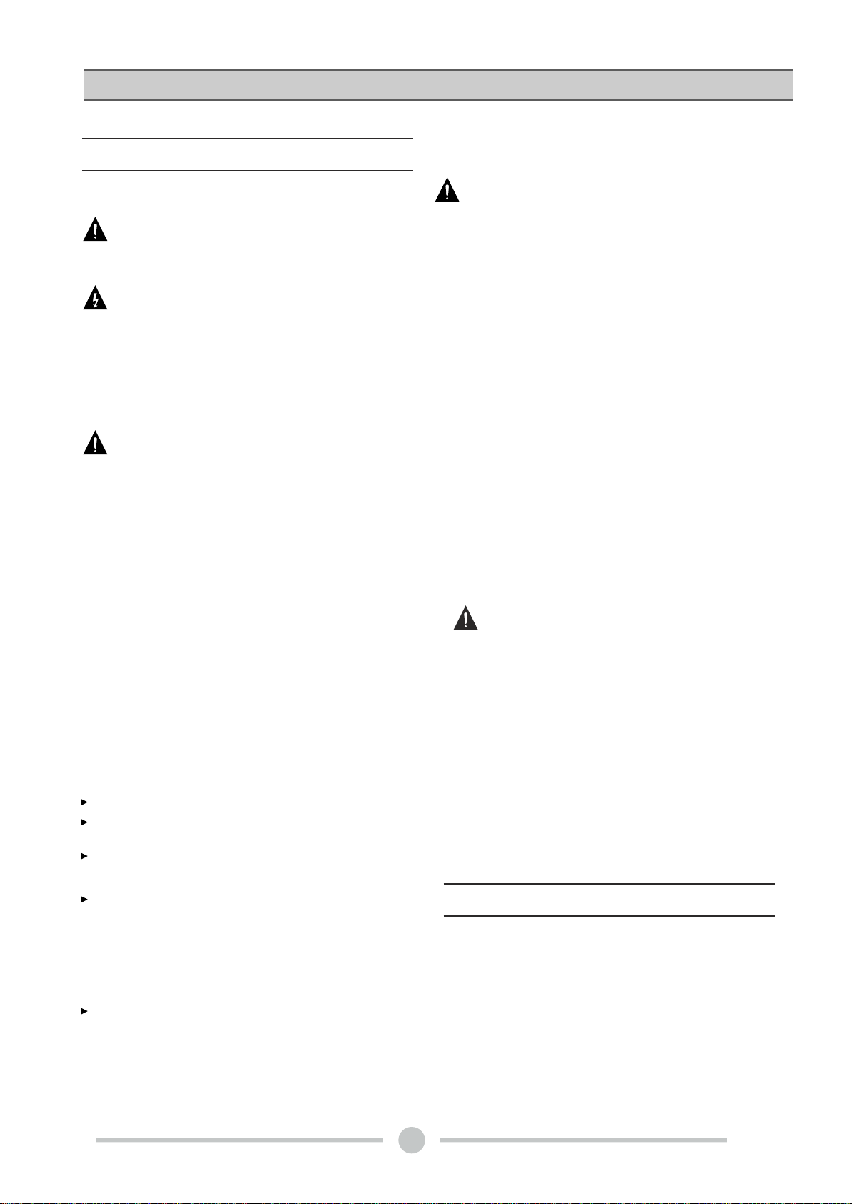
Rear view of 4-channel model fitted with Speakon connectors
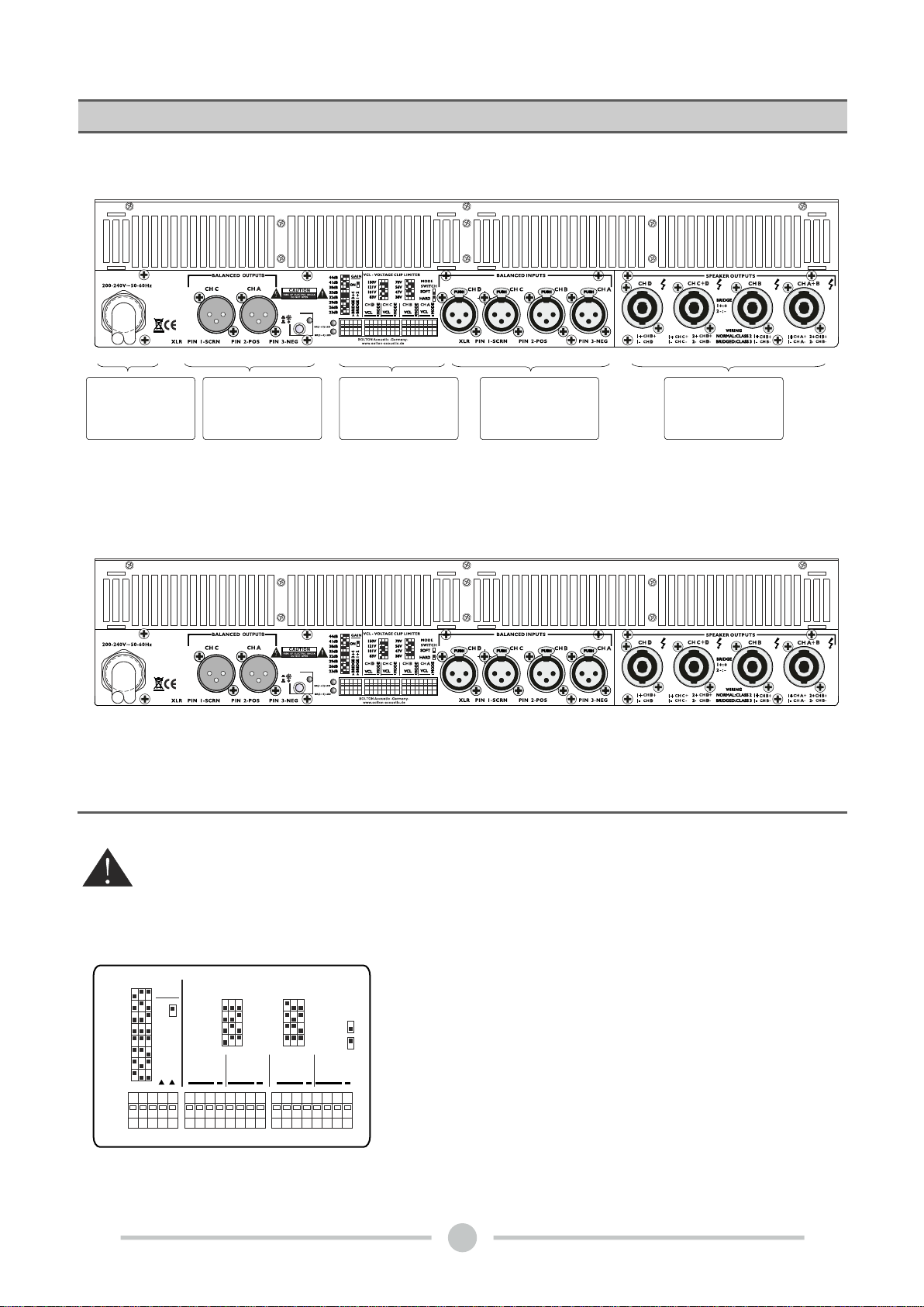
6.2.2 The DIP switch features
The following features may be adjusted using the DIP
switches on the rear-panel of the amplifier.Gain -
Globally set for all channels, from +23 dB to +44dB in 3
dB steps.
Bridge A+B and C+D - Switches the channel pairs into
bridge mode operation An automatic -6 dB gain
compensation is applied.
Four-channel model shown. Two-channel versions have VCL and Bridge Mode switches for
channels1and 2 only. All models have different VCL values.Functions are otherwise
identical.
5
BRIDGE 3+4
BRIDGE 1+2
150V
121V
101V
83V
70V
56V
47V
38V SOFT
HARD
CH 4 CH 3 CH 2 CH 1
VCL
MODE
MODE
VCL
MODE
VCL VCL
MODE
44dB
41dB
38dB
35dB
32dB
29dB
26dB
23dB
VCL - VOLTAGE CLIP LIMITER
MODE
SWITCH
GAIN
ON
Rear panel features introduction
XLR connectors for
inputs and loop thru 4 channel version
shown with Neutrik
Speakon output
connectors
Mains input 200V
or 240V operation DIP switches
for adjusting key
features
(See below)
2 channel version
shown with Neutik
Speakon output
connectors
CHA/CHC
PARALLEL
STEREO
CHA/CHC
PARALLEL
STEREO
6
VCL - Voltage Clip Limiter adjustment is provided for eight
discrete levels for each channel for each channel. Select the
setting most appropriate for connected speakers.
Mode - Select VCL mode to either Hard or Soft operation. For
channels driving sub-woofers and low-frequency drivers, it is
recommended to use the Hard setting for optimal operation. For
mid- and high- frequency drivers, always select Soft.
VCL - VOLTAGE CLIP LIMITER
150V
121V
101V
83V
70V
56V
47V
38V
VCL - in Bridge Mode
DX4
300V
242V
202V
166V
140V
112V
94V
76V
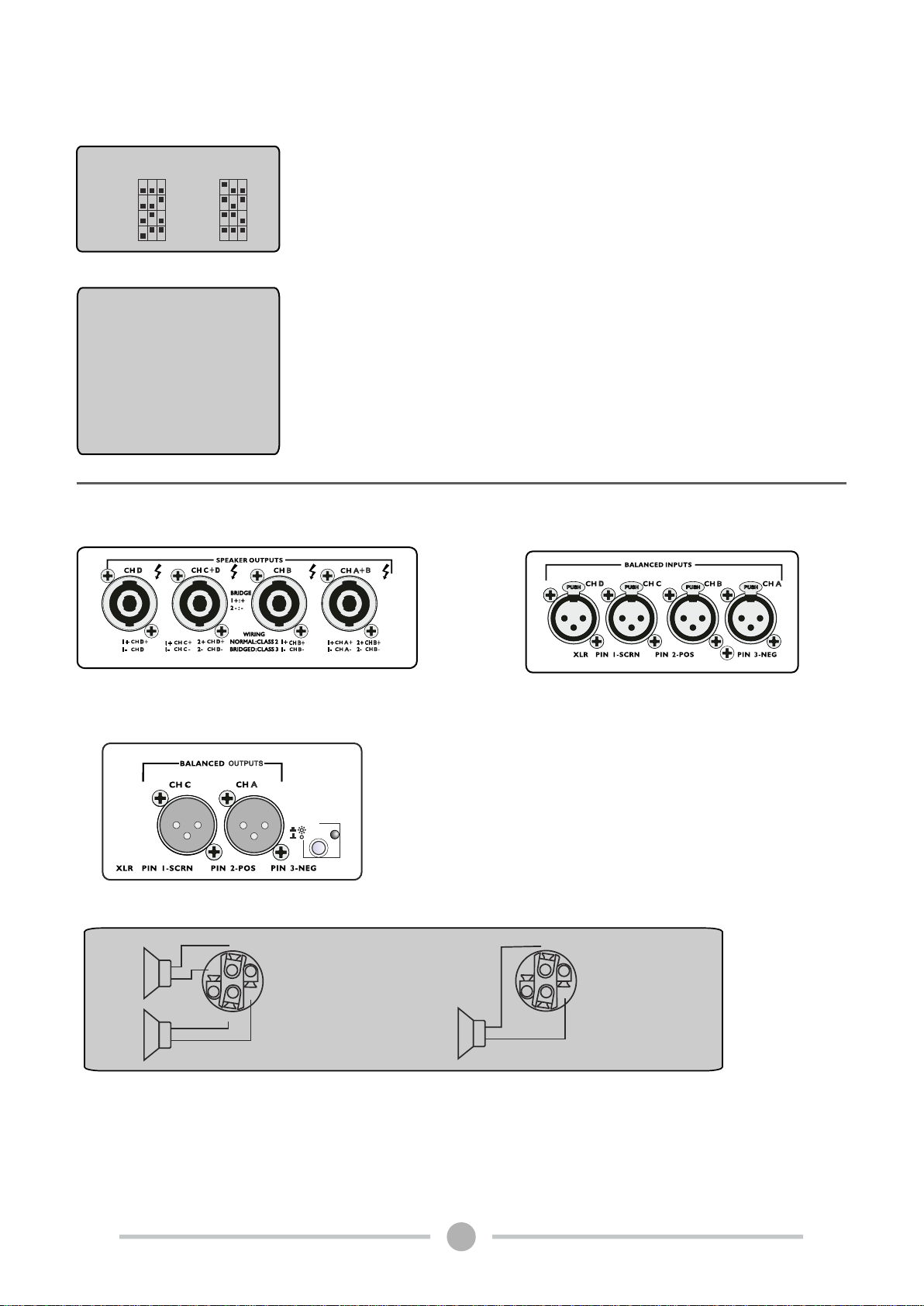
Output connectors
Speakon outputs - 4-channel models
1+
2+
+
-
2-
1-
+
-
+
-+
-
Channel A and B into one
Speakon (Stereo and Bi-amp)
Four-channel amplifiers Additional connectors are provided for Channel C
and Channel D. Channel C functions as Channel A above, and Channel D as
Channel B above.
Link outputs STEREO modelsPARALLEL or
Link outputs PARALLEL or STEREO models:
In stereo models, the signal input into channel A
can be output from channel A only, similarly, the
signal input into channel A or channel C can be
output from channel A and channel C.
Input connectors
Audio inputs - 4-channel models
1+
2+
2-
1-
Bridge mono
CHA/CHC
PARALLEL
STEREO

Audio input and output connections
BALANCED INPUT CONNECTIONS
The XLR input connectors are electronically balanced,
and wired according to the IEC 268 standard(pin 2 =
hot). XLR input connectors should be wiredas follows:
Pin 1 Ground/shield
Pin 2 Hot (+)
Pin 3 Cold (-)
Audio inputs - 4-channel models 1
3
2
Gnd
+
-
When linking the same source signal to several input channels, be aware
that there is a limit to the number of channels an output source can "drive". A
typical output source (e.g. a DSP crossover unit) can drive up to four
amplifier channels before external line-drivers might be required to buffer
the signal.
1
3
2
+
-++
-
To connect an input to an unbalanced source, it is
possible to connect pins 1 and 3 in the XLR plug at the
amplifier end of the cable. However, a better method is
to connect pin 3 to the shield at the source end of the
cable, as this usually results in better hum and noise
rejection. Balanced input connections are recommended
whenever possible.
Unbalanced Input connections
Speakon Output connections
Refer to the instructions in this section if your amplifier is equipped with the Speakon output
connectors.
Speakon outputs - 4-channel models
7
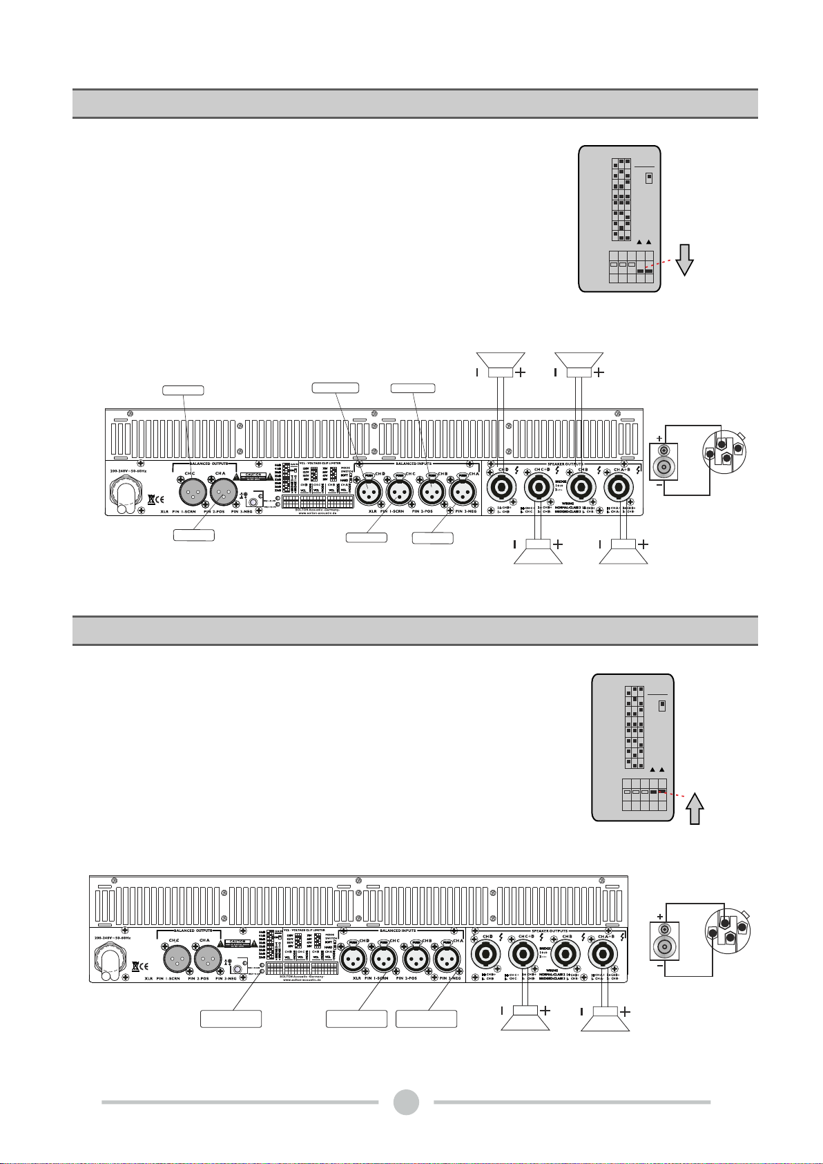
Before setting the mode , please turn off the amplifier and
slide the mode select switch to above (Picture 2), channel A
and channel B are bridged, channel C and channel D are
bridged. At time , the signal input into channel A and channel
C will be output from the bridge end. On other hand , the
output level control of channel B and channel D should be
turn down to smallest . Only the volume control of channel A
and channel C are used to control the volume of whole
1+
1-
2+
2-
Bridge Mode
Before setting the mode , please turn off the amplifier and
slide the mode select switch to below (Picture 1) .In this
mode, Channel A an Channel B operate independently (just
traditional stereo amplifier). The signal input into channel A
can be output from channel A only, similarly, the signal input
into channel B can be output from channel B only. The many
channels , one by one in order type pushes.
1+
1-
2+
2-
Stereo Mode
BRIDGE 3+4
BRIDGE 1+2
44dB
41dB
38dB
35dB
32dB
29dB
26dB
23dB
GAIN
ON
BRIDGE 3+4
BRIDGE 1+2
44dB
41dB
38dB
35dB
32dB
29dB
26dB
23dB
GAIN
ON
8
(Picture 1)
(Picture 2)
Bridge LED
CHA/CHC
PARALLEL
STEREO
CHA/CHC
PARALLEL
STEREO
Channel A
Channel C
Channel A
Channel B
Channel C
Channel D
Channel A
Channel C
Channel B
Channel D
Channel A
Channel C
Channel B
Channel D
Channel C
Channel A
-
-
9
Rear panel features introductionAmplifier Specifications
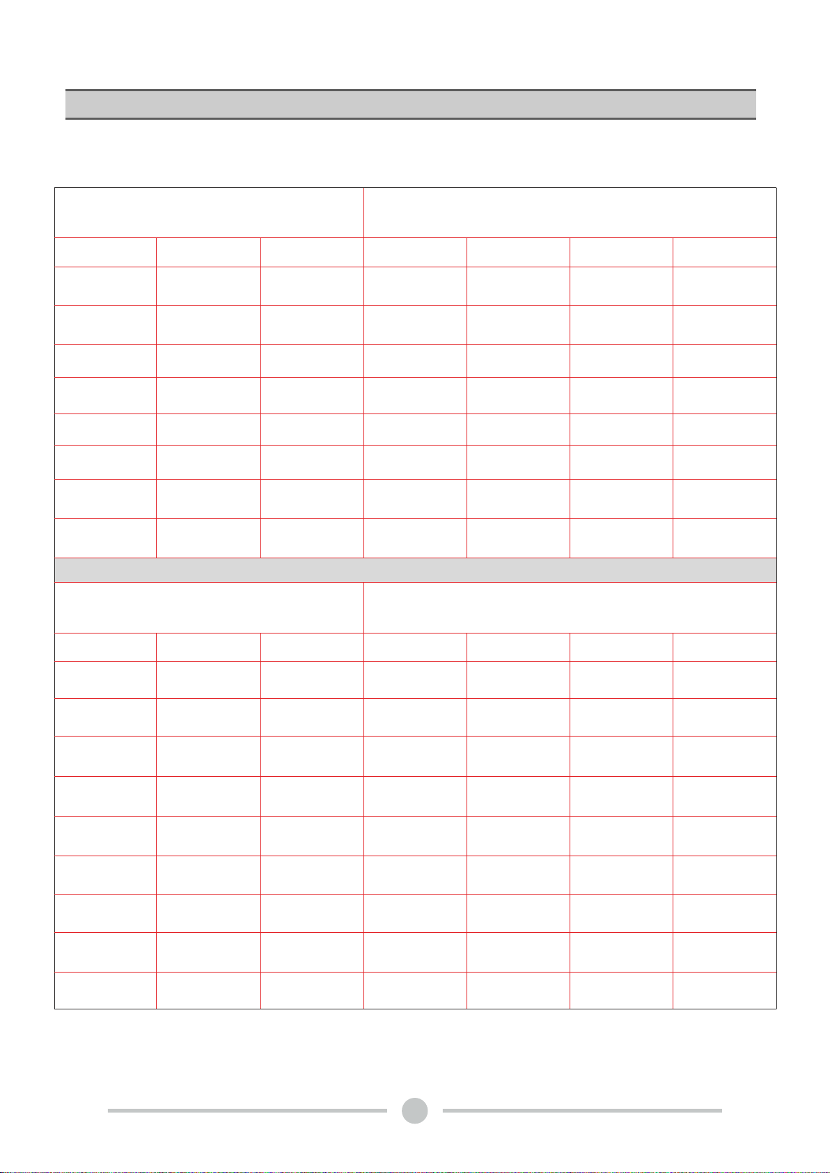
VOLTAGE PEAK LIMITER
OUTPUT POWER PER CHANNEL (W)
LOAD
VPL Setting
V peak
Vrms
16 Ohms
8 Ohms
4 Ohms
2 Ohms
150 V
150
106
620
1240
2485
2500
121 V
121
86
435
870
1740
2500
101 V
101
70
315
625
1250
2500
83 V
83
59
225
450
900
1805
70 V
70
49
160
315
630
1260
56 V
56
40
110
220
435
870
47 V
47
33
80
155
315
625
38 V
38
27
55
110
220
440
VOLTAGE PEAK LIMITER
OUTPUT POWER BRIDGED PER TWO CHANNELS (W)
LOAD
VPL Setting
V peak
Vrms
16 Ohms
8 Ohms
4 Ohms
2 Ohms
38 V
38 V
38 V
38 V
38 V
38 V
38 V
150 V
300 V
212 V
2485
4970
5000
n.r.
121 V
242 V
172 V
1740
3480
5000
n.r.
101 V
202 V
140 V
1250
2500
5000
n.r.
83 V
166 V
118 V
905
1810
3615
n.r.
70 V
140 V
98 V
630
1260
2520
n.r.
56 V
112 V
80 V
435
870
1740
n.r.
47 V
94 V
66 V
315
625
1250
n.r.
38 V
76 V
54 V
220
440
880
n.r.
Rear panel features introduction
10
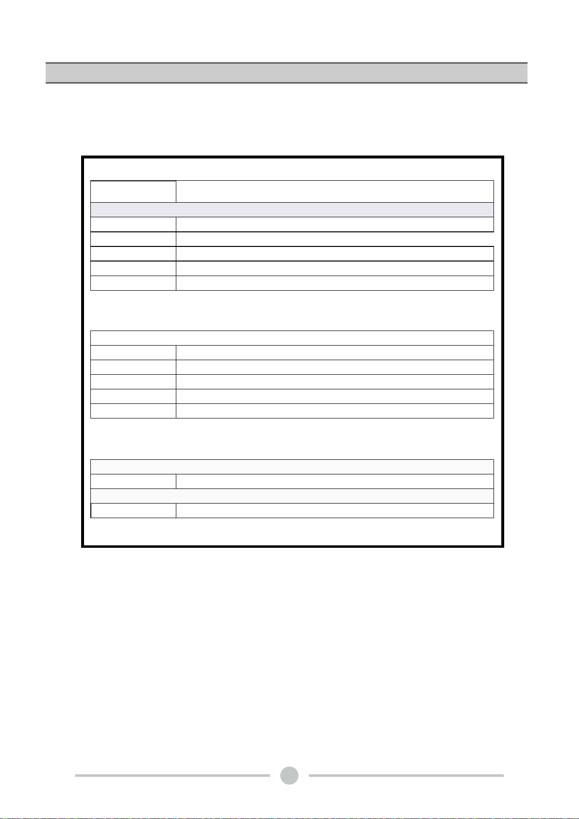
Amplifier Specifications
20kヲBalanced /10kヲUnbalanced
13Kg
0.1%
110dB
Speakon Connectors (NEUTRIK)
+
20Hz-25kHz 0.5dB
-
4 x 1300W
4 x 2200W
4 x 2500W
2 x 4400W
2 x 5000W
Model
8ヲStereo Power
4ヲStereo Power
8ヲBridged Monon Power
4ヲBridged Monon Power
FREQUENTY RESPONSE
THD+N(Rated power,4ヲ/KHz)%
Signal Noise Ration(dB)
Input Impedance
Power Requirement
Weight(net)
Air frame
Output Connectors
Dimension
Weight
2ヲStereo Power
200-240V~50-60Hz
483x377x88mm
DX4
Output Power
c
SOLTON Acoustic
Oberer Mühlweg 6 / 94060 Pocking, Rottau / GERMANY
Tel: +49 (0) 8531 / 913880 Fax: +49 (0) 8531 / 978507
All rights reserved to SOLTONAcoustic. All features and content might be changed
without prior notice. Any photocopy, translation, or reproduction of part of this
manual without written permission is forbidden. Copyright 2020 SOLTONAcoustic
Table of contents
Other Solton Amplifier manuals


Popular Amplifier manuals by other brands

Wisi
Wisi MIDI Series operating instructions

Lab.gruppen
Lab.gruppen LAB 4000 Specifications

Better Music Builder
Better Music Builder DX-222 Quick setup guide

Clarion
Clarion XC6420 Owner's manual & installation manual

Tektronix
Tektronix P6046 instruction manual

LY International Electronics
LY International Electronics PM9006 Operation instructions


