Solton DPA3655QR User manual

Described below are the functions of the front panel control buttons and encoders for the
3IN6OUT Speaker Processor .
• Getting Started
As soon as the 3IN6OUT Speaker Processor is turned ON the de ice model name will appear in the
LCD screen:
and a status bar will show the progress of the 3IN6OUT Speaker Processor initialization process:
After the first time acti ation, the 3IN6OUT Speaker Processor will show on the LCD :

• Encoders and ENTER, ESC buttons
The 3IN6OUT Speaker Processor is equipped with 3 Relati e Encoders, “NAV/PM1”, “PM2” and
“PM3”, These encoders allow you to na igate the user interface and edit sections of the processor.
They allow the user to na igate within the screen for the selection of sub-menus, pages and
parameters and to select the alues to be assigned during the editing operations.
The “ENTER” and “ESC” buttons allow the user to confirm or NOT confirm the operations
performed by the encoders.
• UTILITY, A/B/C and 1/2/3/4/ /6 buttons
The UTILITY button allows the User to enter the Sub-menus and set the general characteristics of
the Processor. The A , B and C buttons allow the User to enter the Editing Menus of the
Processor's Input Channels and buttons 1, 2, 3 , 4, 5, and 6 allow the User to enter the Editing
Menus of the Processor's Output Channels.
The A , B and C buttons as well as the 1, 2, 3, 4, 5 and 6 buttons ha e double functions
dependent on the push and hold time.
When the A , B and C buttons are pushed and held for more than one second Input Channels A or
B or C are either muted or unmuted. The red LED will illuminate when the Channel is muted.
When the “MUTE” LED is OFF, then the related Input Channel is UN-MUTED.
A momentary push of the A , B and C buttons enters the Editing Mode for the Input Channels (see
later for the Input Channel Editing details).
The blue “EDIT” LED will now be ON.
When the 1, 2, 3, 4, 5 and 6 buttons are pushed and held for more than one second the Output
Channels 1, 2, 3, 4, 5 and 6 are either muted or unmuted. The red LED will illuminate when the
Channel is muted. When the “MUTE” LED is OFF, then the related Output Channel is UN-MUTED.
A momentary push of the 1, 2, 3, 4, 5 and 6 buttons enters the Editing Menu for the Output
Channels (see later for the Output Channel Editing details). The blue “EDIT” LED will now be ON.
• 3IN6OUT Speaker Processor Menu and Sub-Menu Structures
As stated abo e, the start-up default screen is the following factory preset:
From this point, sub-menus are accessed and exited using the UTILITY”, “A/B/C”, “1/2/3/4/5/6”,
“ENTER” and “ESC” buttons and all parameters and alues are na igated by the “NAV/PM1”, “PM2”
and “PM3” encoders. Please refer to the following menu structures:

MENU “UTILITY MENU” [Access by pushing the “UTILITY” butt n]
NAV/PM1 Enc der PM2 r PM3 Enc der
[to na igate between menus] [to chose option, then ENTER to load it;
(*) indicates the selected option]
1 UTILITY MENU:......
<< System Utilities >>
1.1 SYSTEM UTILITY: Input S urce
<< Input S urce >> S urce = Anal g input
S urce = Digital Input
S urce = N ise Gen
1.2 SYSTEM UTILITY: N ise Generat r
<< N ise Generat r >> Type = Pink
Type = White
Lev = 0dB
:
Lev = -40dB
1.3 SYSTEM UTILITY: Delay Units
<< Delay Units >> Unit = Distance (m)
Unit = Time(ms)
1.4 SYSTEM UTILITY: Set Default Value
<< Set Default Value >> [Enter] t c nfirm
1. SYSTEM UTILITY: Firmware Versi n
<< Firmware Versi n >> Versi n=2.0.3
2 UTILITY MENU:......
<< Pr gram Utilities >>
2.1 PROGRAM UTILITY: Recall a Pr gram
<< Recall a Pr gram >> P01: Pr gram empty
: :
P32 Pr gram empty
2.2 PROGRAM UTILITY: Save a Pr gram
<< Save a Pr gram >> P01: Pr gram empty
: :
P32: Pr gram empty
2.3 PROGRAM UTILITY: Delete a Pr gram
<< Delete a Pr gram >> P01: Pr gram empty
: :
P32: Pr gram empty
3 UTILITY MENU:......
<< Interface Utilities >>
3.1 INTERFACE UTILITY: Interface Setup
Interface Setup S urce = USB
S urce = RS485 ID=1,…,32
4 UTILITY MENU:......
<< Security Utilities >>
4.1 SECURITY UTILITY: Parameter will
Sh w Parameter be sh wn
n t be sh wn
4.2 SECURITY UTILITY: L ck Unit
L ck Unit L ck = Off
L ck = On
4.3 SECURITY UTILITY: Change Passw rd
Change Passw rd [ ]
4.4 SECURITY UTILITY: Enter Passw rd
L ck With Passw rd [ ]
ENTER
ESC
ENTER
ESC
ENTER
ESC
ENTER
ESC
ENTER
ESC
ENTER
ESC
ENTER
ESC
ENTER
ESC
ENTER
ESC
ENTER
ESC
ENTER
ESC
ENTER
ESC
ENTER
ESC

MENU “ In put A/B/C ” In put Channels Editing [Access by pushing the “ A / B / C ” butt n]
NAV/PM1 Enc der NAV/PM1 Enc. PM2 Enc. PM3 Enc.
[to na igate between menus] [to chose alues for the parameters, no need to confirm the chosen alues,
which are automatically loaded during the encoders use]
1. Input A/B/C [Name] Name
Name = [Name]
-> Name = _ (For Editing the Device's Name, refer to the Details on the“Utility Menus Use” Section
2. Input A/B/C [Name] N.Gate
Bypass=On
-> Bypass=On PM1 N/A. Byp=On/Off Thr=-80.0dBu … -50 dBu
Rel=10ms … 1000ms Atk=1ms … 1000ms
3. Input A/B/C Gain
Gain = + 0.0 dB
-> Gain = + 0.0 dB PM1 N/A. -18 dB 0.1dB
: :
+12dB 0.9dB
Step 1dB Step 0.1dB
4. Input A/B/C Delay
Delay = 0.000 ms
-> Delay = 0.000 ms PM1 N/A. 000.0000mS 000.0000mS
[1 ms steps] [10.4 us steps]
310.0000mS 000.9984mS
5. Input A/B/C [Name] Phase
Phase=N rmal
-> Phase=N rmal PM1 N/A. Phase= N rmal/Invert
6. Input A/B/C [Name] RMS Cmp
Bypass=On
-> Bypass=On PM1 N/A. Byp=On/Off
PM1 N/A. Threshold=+20dBu … -10dBu
PM1 N/A. Ratio =2:1 … 32:1 Knee=0% … 100%
PM1 N/A. Rel=0.1sec … 3.0sec Atk=5ms … 200ms
PM1 N/A. Make-up=-12dB … +12dB
7. Input A/B/C [Name] ALLPass-X (1 t 3 )
Bypass Freq=1000Hz
-> Bypass Freq=1000Hz PM1 N/A. Filter=Bypass/1st-order/2nd-order
PM1 N/A. Frequency=20Hz … 20000Hz
Filter=2nd-order PM1 N/A. Q Factor=0.5 … 9.9
8. Input A/B/C [Name] EQ Byp
Bypass=On
-> Bypass=On PM1 N/A. Bypass=On/Off
9. Input A/B/C [Name] PEQ-XX(00 t 18)
Byp= n Type=Peaking_Eq

-> Byp= n Type=Peaking_Eq PM1 N/A. Byp=On/Off Type=Peaking_Eq/ Hi -Shel 1/ Hi -Shel 2/ Hi
-Shel Q/ Lo-Shel 1/ Lo-Shel 2/Lo-Shel Q/ Low-Pass 1/ Low-Pass 2/Low-Pass Q/High-Pass1/ High-Pass2/High-Pass Q/Band-Pass/ Notch
Type=Peaking_Eq PM1 N/A. Frequency=20Hz … 20000Hz
PM1 N/A. Gain=-15dB … +15dB Q=0.4 … 128
Type= Hi -Shel 1/ Hi -Shel 2 PM1 N/A. Frequency=20Hz … 20000Hz
PM1 N/A. Gain=-15dB … +15dB Q=Fixed
Type= Hi -Shel Q PM1 N/A. Frequency=20Hz … 20000Hz
PM1 N/A. Gain=-15dB … +15dB Q=0.1 … 5.1
Type= Lo-Shel 1/ Lo-Shel 2 PM1 N/A. Frequency=20Hz … 20000Hz
PM1 N/A. Gain=-15dB … +15dB Q=Fixed
Type= Lo-Shel Q PM1 N/A. Frequency=20Hz … 20000Hz
PM1 N/A. Gain=-15dB … +15dB Q=0.1 … 5.1
Type= Low-Pass 1/ Low-Pass 2 PM1 N/A. Frequency=20Hz … 20000Hz
Type= Low-Pass Q PM1 N/A. Frequency=20Hz … 20000Hz
PM1 N/A. Gain=-Fixed Q=0.1 … 5.1
Type= High-Pass1/ High-Pass2 PM1 N/A. Frequency=20Hz … 20000Hz
Type= High-Pass Q PM1 N/A. Frequency=20Hz … 20000Hz
PM1 N/A. Gain=-Fixed Q=0.1 … 5.1
Type= Band-Pass PM1 N/A. Frequency=20Hz … 20000Hz
PM1 N/A. Gain=-15dB … +15dB Q=4 … 104
Type= Notch PM1 N/A. Frequency=20Hz … 20000Hz
PM1 N/A. Gain=Fixed Q=4 … 104

MENU “Output 1/2/3/4 /5/6 ” Output Channels Editing [Access by pushing the “1/2/3/4 /5/6 ” butt n]
NAV/PM1 Enc der NAV/PM1 Enc. PM2 Enc. PM3 Enc.
[to na igate between menus] [to chose alues for the parameters, no need to confirm the chosen alues,
which are automatically loaded during the encoders use]
1. Output[x] [Name] Name
Name = [Name]
-> Name = _ (For Editing the Device's Name, refer to the Details on the“Utility Menus Use” Section
2. Output[x] [Name] S urce
InA=On InB=Off InC=Off
-> InA: Level=0dB On PM1 N/A 0 dB On/Off
:
-30dB
-> InB: Level=0dB Off PM1 N/A 0 dB On/Off
:
-30dB
-> InC: Level=0dB Off PM1 N/A 0 dB On/Off
:
-30dB
3. Output[x] [Name] Gain
Gain = + 0.0 dB
-> Gain = + 0.0 dB PM1 N/A -18 dB 0.1dB
: :
+12dB 0.9dB
Step 1dB Step 0.1dB
4. Output[x] [Name] Delay
Delay = 0.000 ms
-> Delay = 0.000 ms PM1 N/A 000.0000mS 000.0000mS
[1 ms steps] [10.4 us steps]
270.0000mS 000.9984Ms
5. Output[x] [Name] Phase
Phase=N rmal
-> Phase=N rmal PM1 N/A. Phase= N rmal/Invert Same as PM2
6. Output[x] [Name] Limiter
Bypass=On
-> Bypass=On PM1 N/A. Bypass= On/Off
PM1 N/A. Thresh ld=-10dBu … 20 dBu
PM1 N/A. Rel=0.1sec … 5sec Atk=1ms … 900ms
7. Output[x] [Name] HPF
20.0 Hz Bypass
-> 20.0 Hz Bypass PM1 N/A [Freq.] 20Hz [Type/Slope] Bypass
: :
20kHz LR -48 dB /Oct
Sl pe=Bypass/ BW -6 dB/Oct / BW -12 dB/Oct / LR -12 dB/Oct / BS -12 dB/Oct / BW -18 dB/Oct / BW -24 dB/Oct / LR -24 dB/Oct / BS -24
dB/Oct / BW -36 dB/Oct / LR-36 dB/Oct / BW -48 dB/Oct / LR-48 dB/Oct /
8. Output[x] [Name] LPF
20.0 Hz Bypass

-> 20.0 Hz Bypass PM1 N/A [Freq.] 20Hz [Type/Slope] Bypass
: :
20kHz LR -48dB/Oct
Sl pe=Bypass/ BW -6 dB/Oct / BW -12 dB/Oct / LR -12 dB/Oct / BS -12 dB/Oct / BW -18 dB/Oct / BW -24 dB/Oct / LR -24 dB/Oct / BS -24
dB/Oct / BW -36 dB/Oct / LR-36 dB/Oct / BW -48 dB/Oct / LR-48 dB/Oct /
9. Output[x] [Name] EQ Byp
Bypass=On
-> Bypass=On PM1 N/A. Bypass=On/Off
10. Output[x] [Name] PEQ-XX(00 t 07)
Byp= n Type=Peaking_Eq
-> Byp= n Type=Peaking_Eq PM1 N/A. Byp=On/Off Type=Peaking_Eq/ Hi -Shel 1/ Hi -Shel 2/ Hi
-Shel Q/ Lo-Shel 1/ Lo-Shel 2/Lo-Shel Q/ Low-Pass 1/ Low-Pass 2/Low-Pass Q/High-Pass1/ High-Pass2/High-Pass Q/Band-Pass/ Notch
Type=Peaking_Eq PM1 N/A. Frequency=20Hz … 20000Hz
PM1 N/A. Gain=-15dB … +15dB Q=0.4 … 128
Type= Hi -Shel 1/ Hi -Shel 2 PM1 N/A. Frequency=20Hz … 20000Hz
PM1 N/A. Gain=-15dB … +15dB Q=Fixed
Type= Hi -Shel Q PM1 N/A. Frequency=20Hz … 20000Hz
PM1 N/A. Gain=-15dB … +15dB Q=0.1 … 5.1
Type= Lo-Shel 1/ Lo-Shel 2 PM1 N/A. Frequency=20Hz … 20000Hz
PM1 N/A. Gain=-15dB … +15dB Q=Fixed
Type= Lo-Shel Q PM1 N/A. Frequency=20Hz … 20000Hz
PM1 N/A. Gain=-15dB … +15dB Q=0.1 … 5.1
Type= Low-Pass 1/ Low-Pass 2 PM1 N/A. Frequency=20Hz … 20000Hz
Type= Low-Pass Q PM1 N/A. Frequency=20Hz … 20000Hz
PM1 N/A. Gain=-Fixed Q=0.1 … 5.1
Type= High-Pass1/ High-Pass2 PM1 N/A. Frequency=20Hz … 20000Hz
Type= High-Pass Q PM1 N/A. Frequency=20Hz … 20000Hz
PM1 N/A. Gain=-Fixed Q=0.1 … 5.1
Type= Band-Pass PM1 N/A. Frequency=20Hz … 20000Hz
PM1 N/A. Gain=-15dB … +15dB Q=4 … 104
Type= Notch PM1 N/A. Frequency=20Hz … 20000Hz
PM1 N/A. Gain=Fixed Q=4 … 104

Menu “UTILITY” [access by pushing the “UTILITY” butt n]
From the “Default Screen”, it is possible access the “UTILITY” menu pushing the “UTILITY” button
and the Sub-Menus pages can be selected just rotating clockwise and counter-clockwise the
“NAV/PM1” encoder.
Once selected the sub-menu page, using the “ENTER” button can be accessed the Sub-Menus
pages, again “scrollable” using the “NAV/PM1” encoder and accessible for the parameters' editing
pushing again the “ENTER' button.
Through the “ESC” button, it is any time possible to go back to the action and page operation
preceding the “ENTER” button use.
Once inside the Sub-Menus pages, the se eral options can be scrolled by rotating the PM2 or PM3
encoders and selected/confirmed by pushing the “ENTER” button.
System Utilities Sub-menu – this sub-menu allows to access se eral operations related to the
3IN6OUT Speaker Processor Start Up and General Configuration:
From the “System Utilities Sub-menu”, pushing “ENTER” and then using the “NAV/PM1” encoder
for scrolling will gi e access to the following pages:
Input S urce: the 3IN6OUT Speaker Processor is equipped with 3 Analog Inputs (Balanced
Female XLR) and a stereo S/PDIF Digital Input (RCA connector).and noise generator
The “Input Source” page allows you to select the desired Input type:
By pressing ENTER on Input Source and then rotating the “PM2” or “PM3” encoders, it is
possible to select the Main Inputs for the 3IN6OUT Speaker Processor, allowing the User to
choose between Analog , S/PDIF Digital or Noise Generator.
The selection can be confirmed by pressing the “ENTER” button.
The following screen shows that the Analog Input has been selected:

N ise Generat r: 3IN6OUT Speaker Processor equips with 2 types of noise generator: White
Noise and Pink Noise.
By pressing ENTER and rotating the “PM2” encoder, it is possible to select between those 2
choice: “Pink” or “White”. By rotating the “PM3” encoder, it is possible to set the alue of le el
of white noise generator and pink noise generator, with whose range from 0dB to -40dB.
The following screen shows the selected pink noise with le el of -20dB:
Delay Time/Distance: this page allows you to select the measurement unit to be used for
the Delays: Time (in milliseconds “ms”) or Distance (in meters “m”):
By pressing ENTER button and rotating the “PM2” or “PM3” encoder, it is possible to select the
measurement unit to be used for the delay, which will be confirmed by pushing the ENTER
button.
The following screen shows the selected delay measurement is Time (milliseconds)
Set Default Value: All setting for 3IN6OUT Speaker Processor can be set to default alue:
By pressing ENTER button, will show up the following screen of an interface to confirm to set
the default alue:
By pressing ENTER button one more time, will show up the following screen:

Wait around 3 sec for the processor set to the default alue.
Firmware Versi n: this page allows you to confirm the Firmware Version running on the
3IN6OUT Speaker Processor:
The correct Version is “2.0.3”
Program Utilities Sub-menu – this sub-menu allows you to access se eral options related to
the 3IN6OUT Speaker Processor operating mode and to manage the presets stored and recallable
within the Unit:
By pressing the ENTER button and then using the “NAV/PM1” encoder to scroll, the following
pages can be accessed:
Recall a Pr gram: this page allows the Loading of a preset program. You can store up to 32
presets in the 3IN6OUT Speaker Processor memory:
By pressing ENTER and rotating the “NAV/PM1” encoders, it is possible to scroll through all
current a ailable presets.
If NO USER PRESETS are stored yet, the screen will show the following:
If presets ha e pre iously been stored by the user, anyone of them can be recalled:
By using the “NAV/PM1” encoder it is possible to scroll through the stored presets. Once the
desired preset appears on the screen, select it by pressing the “ENTER” button and this will
force the 3IN6OUT Speaker Processor to begin to load this selected preset and the following

transitory screen will appear:
Once loaded the 3IN6OUT Speaker Processor will exit to the “Recall a Program” screen
automatically and the abo e screen will disappear:
N te: at any time it is possible to quit the recalling action by pressing the “ESC” button.
Save a Pr gram: this page allows you to store a new preset in the 3IN6OUT Speaker
Processor’s memory:
By pressing the ENTER button and rotating the “NAV/PM1” encoder, it is possible to scroll
through the pre iously sa ed presets or the a ailable empty locations (identified by “Program
empty”).
If no user presets are stored, the “Sa e a Program” screen will show empty memory locations
for all 1-32 presets as shown in the example below for location 10:
When storing an edited configuration for the 3IN6OUT , select the location for a preset from
the 32 available by using the “NAV/PM1” encoders.
Once the desired location appears on the screen press ENTER button again to reach the “Edit
Pr gram Name” page.
In this page the User can enter a Preset Name (up t 16 Characters) by using the “PM3”
encoder to choose a character and the “PM2” encoder to mo e between the 16 a ailable
locations for the character’s positioning.
The current position of the cursor is shown by a “blinking underscore”.
The following is an example of a screen while entering the preset name “Stage 1 2x2” in
location 10:

To store the Preset Name press the “ENTER” button again.
The abo e action will take you to the “Enter t Save” page showing the selected location for
the preset and the final edited name:
Pressing “ENTER” again, will store the preset in the selected location with the chosen name
and the following transitory screen will appear on the LCD:
Once the preset is stored, the abo e screen will disappear returning to the following screen:
If during the Preset Storing process you want to o erwrite an existing memory location select
this location in the “Set Pr gram Name” page, then press ENTER button and you will be
asked if you want to o erwrite this preset with the following “[ENTER] t Overwrite” screen
displaying the currently stored preset and location:
If you wish to proceed press “ENTER” again and the 3IN6OUT Speaker Processor will go ahead
with the “Set Pr gram Name” page and the subsequent o erwrite on completion of the
pre iously described storing process..
N te: at any time it is possible to quit the storing action by pressing the “ESC” button.
Delete a Pr gram: this page allows you to delete a preset already stored in the 3IN6OUT
Speaker Processor memory:
By pressing the ENTER button and rotating the “NAV/PM1” encoder, it is possible to scroll
through the pre iously sa ed presets and the a ailable empty locations (identified by “Program
empty”).
If no user presets are stored, the “Delete a Program” screen will show empty memory
locations for all 1-32 presets as shown in the example below for location 10:

If Presets are a ailable they will be shown in the “Delete a Program” page as follows:
By using the “NAV/PM1” encoder it is possible to select a preset to be deleted.
Pressing the “ENTER” button on a selected preset will bring up the “[Enter] t Delete.” page
showing the selected preset.
For example, if we want to delete the preset 10, “Stage 1 2x2”, the screen will be the
following:
Confirming the deletion by pressing “ENTER” again, will force the 3IN6OUT Speaker Processor
to erase the selected preset and the following transitory screen will appear:
Once the preset is deleted, the abo e screen will disappear returning to the following screen:
N te: At any time it is possible to quit the deleting action by pressing the “ESC” button.
Interface Utilities Sub-menu – this sub-menu allows you to define the remote control interface
[USB or RS485] to be used for controlling the 3IN6OUT Speaker Processor:
From “Interface Utilities”, press “ENTER” button to access the Interface Setup.
Interface Setup: this screen allows you to choose the communication source for the
3IN6OUT Speaker Processor’s.

By using the PM2 encoder you can choose between the two possible interfaces (USB or RS485)
for the 3IN6OUT Speaker Processor.
If select RS485, select the ID by using “PM3” encoder, with its range from 01 to 32.
The following screen displaying the currently selected interface as USB:
The following screen displaying the currently selected interface as RS485:
Security Sub-menu – this sub-menu allows the User to set the parameters shown, lock the
3IN6OUT Speaker Processor and set a Password therefore limiting the unit's functions and controls
to those who ha e only access to the appropriate Password.
Press ENTER and then use the “NAV/PM1” encoder to scroll between options.
Sh w Parameter: Pressing ENTER button from the abo e menu will access the “Show
Parameter” Sub Menu
Press ENTER button again and use the PM2 or PM3 encoders to select between “be shown” or
“not be shown” options.
Choosing the “be shown” option means that once the unit is locked, you cannot access
parameter editing features, but they will be displayed on the LCD screen.
Choosing the “not be shown” option means that once the unit is locked, the parameters will
not be shown at all. With this option, when trying to access a parameter, the following screen
message will appear:
L ck Unit: this sub-menu allows the user to lock the de ice so no parameters can be edited
or modified.

When the Unit is in an unlocked condition, all parameters will be a ailable for editing. When
you select On, all parameters will be locked and are not a ailable for editing.
When you select lock from the menu, the unit will be locked and the lock menu automatically
exited. The screen will re ert to the “Default” showing the current XOVER configuration and
the preset selected and beside the preset’s name a “keylock” icon indicating that the 3IN6OUT
Speaker Processor is locked.
Change Passw rd: from the “Change Password” sub-menu:
Press “ENTER” to access the “Change Passw rd” page:
Use the PM2 encoder to mo e between a ailable locations, and the PM3 encoder to choose a
character. The current position of the cursor for the characters to be entered is shown by a
“blinking underscore”.
Input the original password “000000” for the 3IN6OUT Speaker Processor, and press ENTER
button, will access to the “New Passw rd” Page. Use the PM2 encoder to mo e between
a ailable locations, and rotate the PM3 encoder to edit a 6-position new password.
The following screen is the example with the new password after edition is “111111”
Press the ENTER button again, will access the “C nfirm passw rd” page, use the “PM2”
encoder to mo e between a ailable locations and rotate “PM3” encoder to choose a character,
input the new password edited just now.

The following screen is the example with typing in new password “111111” edited just now.
Press the ENTER button one more time, the new password will be set successfully.
L ck With Passw rd: from the “Lock With Password” sub-menu:
There’s limitation to the editing function if the 3IN6OUT Speaker Processor is locked with
password. All functions for this unit are banned, including MUTE A/B/C and MUTE 1/2/3/4/5/6
buttons.
Press “ENTER” to gain access to the “Enter Passw rd” screen:
Use the “PM2” encoder to mo e between a ailable locations, and rotate “PM3” encoder to select
characters. If the password of this 3IN6OUT Speaker Processor ne er modified, input the default
password “000000”, the unit will be locked. In this case, default screen will show a “Key” icon,
user cannot enter into the sub-menu, unless he holds the password.
Menu “Input A/B/C” Input Channels Editing [access by pushing the “A/B/C”
butt ns]
From the “Default Screen”, it is possible to access the “Input A/B/C” menu by pushing the “A” or
“B” or “C” button. Once the button is pressed, the related blue “EDIT” LED will turn ON. The
Sub-Menu pages can now be scrolled through by rotating clockwise and counter-clockwise the
“NAV/PM1” encoder.
For parameter editing it is necessary to press ENTER button and an arrow will appear on the left of
the screen “->”. Then use the “PM2” and “PM3” encoders for editing and setting the parameter
alues. On some parameters that ha e three independent alues, you will also need to use the
PM1 encoder, eg filter parameter settings.
N te: All options can be done using the “NAV/PM1”, “PM2”, and “PM3” encoders and the current
shown alue of the selected option is AUTOMATICALLY loaded during the encoders' use and stored
as the current alue once lea ing the page.
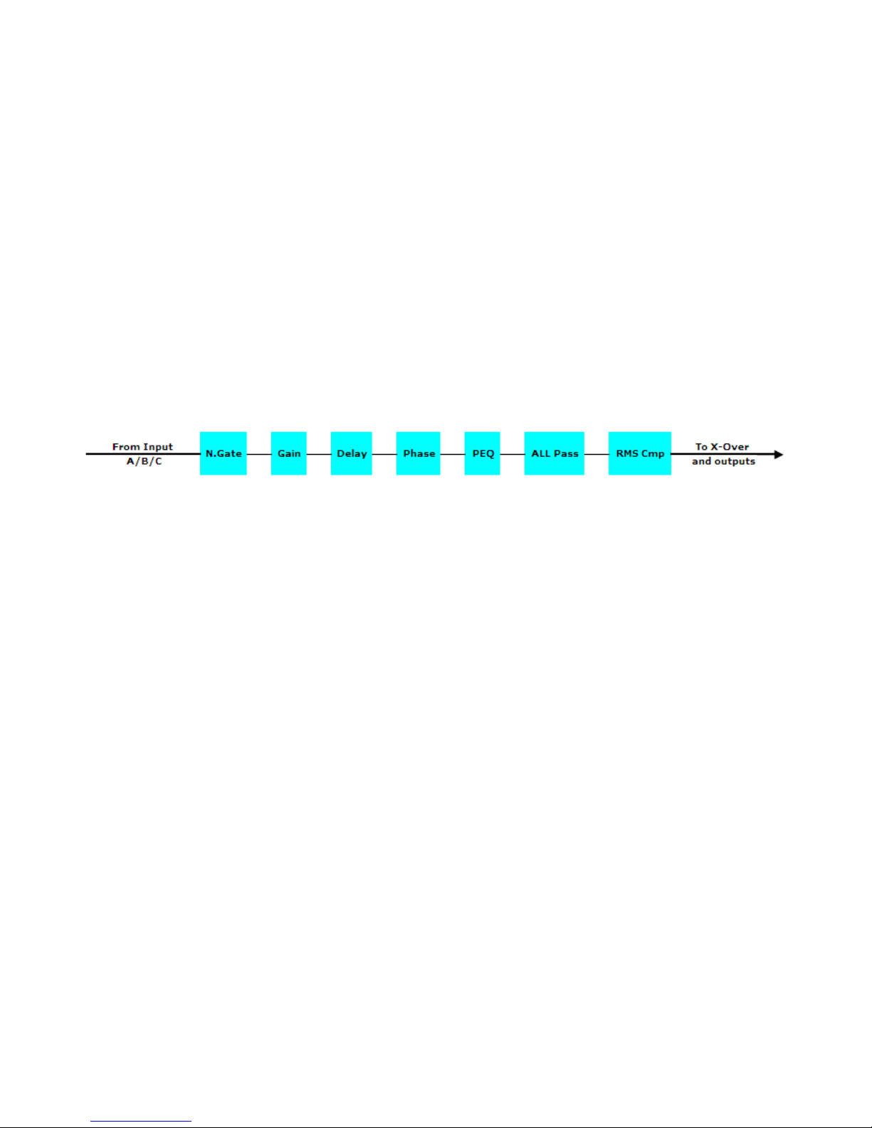
Audi Signal Input (A/B/C) Path Bl ck Scheme
Name page – from this screen, it is possible to assign input channel a name with 6 characters
For example, name the Input A as “In L” in the Name Page:
By pressing ENTER in the Name page, user can edit the name, and there will be an arrow, as the
following screen shows:
The first character will flash.
Select character from these 6 positions by rotating “PM2” encoder and choose the desired
characters by rotating “PM3” encoder. Once the new name is defined, for example, “In A”, confirm
this new name by pressing ENTER… A new name will display on the screen, after replaced the old
one.
The following screen is shown with the new name “In A”, by replacing the pre ious one “In L”
N.Gate page– from this page, it is possible to set the Input Channels Noise Gate. Noise gate can
be set as “ON” or “OFF” status. The following screen is the selected “ON” status:

By pressing ENTER button in this page, an arrow “->” will show up on the left of the screen, and
enter into the setting interface 1 of the noise gate:
By using the “PM2” encoder, it is possible to set the noise gate as “ON” or “OFF”. By using the
“PM3” encoder, it is possible to select its attack threshold from -80dBu to -50dBu.
By rotating “NAV/PM1” encoder, user can enter into the setting interface 2 of the noise gate:
By using “PM2” encoder, user can set noise gate release time: from 10ms to 1000ms, and using
“PM3” encoder to set noise gate attack time: from 1ms to 1000ms.
Gain page – from this screen it is possible to set the Input Channels Le el from -18dB to +12dB,
press ENTER button, an arrow will appear on the left of the screen “->” then use the “PM2” or
“PM3” to set parameters.
The alue set on this screen will only affect the input le el of the selected Channel A or B.
The following is an example screen for the “Gain” page that has set the Gain of Input Channel A to
+0.0dB:
Delay page – from this page it is possible to set the Input Channels Delay Time from
000.0000mS up to 310.9984mS, by steps of 1mS or 10.4uS.
To set the Delay time press ENTER, an arrow will appear on the left of the screen “->”. then use
the “PM2” encoder to set the Delay Time in steps of 1mS and the “PM3” for setting the “fine”
Delay Time in steps of 10.4 microseconds.
The following is an example screen for the “Delay” page where the Delay Time of Input Channel A
is set to 160.1872mS:
Phase page– from this page, it is possible to set input channels phase as “Normal” or “In ert”.
The following is an example screen of “Normal” Phase:

By pressing ENTER button in this page, an arrow will appear on the left of the screen “->”. then
use the “PM2” or “PM3” encoder for setting “Normal” or “In ert” Phase.
RMS Cmp page– from this page, it is possible to set RMS Compressor for input channels. RMS
Compressor can be set as “ON” or “OFF” status. The following is an example screen of “ON”
status:
By pressing ENTER in this page, an arrow will appear on the left of the screen “->”. Then enter
into the setting interface 1 of RMS Compressor.
RMS compressor status can be set as “ON” or “OFF” by using “PM2” or “PM3” encoder.
By rotating “NAV/PM1” encoder, user can enter into setting interface 2 of RMS Compressor:
RMS Compressor attack threshold can be set with “PM2” or “PM3” encoder, with its range from
-10dBu to +20dBu.
By rotating “NAV/PM1” encoder one more time, user can enter setting interface 3 of RMS
Compressor:
RMS Compressor ratio can be set by “PM2” encoder, with its range rom 2:1 ~ 32:1. RMS
Compressor knee can be set by “PM3” encoder, with its range from 0% ~ 100%.
By rotating “NAV/PM1” encoder once again, user can enter setting interface 4 of RMS Compressor:
RMS Compressor release time can be set by “PM2” encoder, with its selectable range from 0.1s ~
3s, and its attack time can be set by “PM3” encoder from 5ms ~ 200ms.
By rotating “NAV/PM1” encoder, user can enter setting interface 5 of RMS Compressor:

By using “PM2” and “PM3” encoder, user can set RMS Compressor make up, from -12dBu to
+12dBu.
Allpass-x(1to3) page – from this page, it is possible to set input allpass filter for input channels,
and to set 3 input allpass filters in its sub-menu, with 3 a ailable types: bypass, 1st order and 2nd
order.
By pressing ENTER button in this page, an arrow will appear on the left of the screen “->”, then
enter setting interface 1 of current input allpass filter:
By using “PM2” or “PM3” encoder, user can select allpass filters from 3 types: bypass, 1st order
and 2nd order.
By rotating “NAV/PM1” encoder, user can enter setting interface 2 of input allpass filter:
By using “PM2” or “PM3” encoder, user can set the allpass filter frequency, with its range from
20Hz to 20kHz.
When the allpass filter is selected as the 2nd order type, rotate the “NAV/PM1” encoder will enter
into setting interface 3 of current input allpass filter:
By using “PM2” or “PM3” encoder, user can select Q Factor of this allpass filter, from 0.5 to 9.9.
EQ Byp page – in this page, it is possible to set EQ Bypass of input channels, with its selectable
status of “ON” and “OFF”. Following is the example screen as Bypass ON:
By pressing ENTER in this page, an arrow will appear on the left of the screen “->”, then enter
setting interface of EQ Bypass:


