Solution 540 User manual

Digital
DigitalDigital
Digital-
--
-Player 540
Player 540Player 540
Player 540
User m
User mUser m
User manual
anualanual
anual
soulution
nature of sound


Digital
DigitalDigital
Digital-
--
-Player
PlayerPlayer
Player
540
540540
540
User manual
Page 1
Dear client
Dear clientDear client
Dear client
We are proud that you decided yourself for a soulution product. You have ac uired a
product with outstanding sonic performance which you will enjoy for many years.
We understand your eagerness to get started but even though please study this
manual step by step before you integrate the Digital-Player 540 in your High Fidel-
ity system. This manual contains also useful tips for the optimisation of your overall
HiFi-system.
If there are any uestions regarding the start-up or operation of your Digital-Player
540 please do not hesitate to contact your dealer.
Have fun!
Have fun!Have fun!
Have fun!
your
youryour
your soulution Team
soulution Team soulution Team
soulution Team

soulution
nature of sound
Page 2
CE
CECE
CE-
--
-Declaration of Conformity
Declaration of ConformityDeclaration of Conformity
Declaration of Conformity
Spemot AG declares that this product is in conformance with the following direc-
tives and standards:
Low Voltage Directive 2006/95/EG (EN/IEC 60065:2002)
Electromagnetic Compatibility 2004/108/EG (EN 55013:2001, EN 55020:2002,
EN 61000-3-2:2006, EN61000-3-3:1995)
FCC
FCCFCC
FCC-
--
-Notice
NoticeNotice
Notice
Note: This e uipment has been tested and found to comply with the limits for a
Class B digital device, pursuant to Part 15 of the FCC Rules. These limits are de-
signed to provide reasonable protection against harmful interference in a residential
installation. This e uipment generates, uses and can radiate radio fre uency energy
and, if not installed and used in accordance with the instructions, may cause harm-
ful interference to radio communications. However there is no guarantee that inter-
ference will not occur in a particular installation.
If this e uipment does cause harmful interference to radio or television reception,
which can be determined by turning the e uipment off and on, the user is encour-
aged to try to correct the interference by one or more of the following measures:
-
adjust or relocate the receiving antenna
-
increase the separation between the e uipment and the receiver
-
connect the e uipment into a mains outlet on a circuit different from that to
which the receiver is connected
-
consult the dealer or an experienced radio/TV technician for help
Disposal
DisposalDisposal
Disposal
According to the Directive 2002/96/EG of the European Parliament used
consumer-electro technical appliances have to be disposed separately
and have to be indicated with the following symbol.
In the case of disposal of this component please do so in conformity with legal and
environmental regulations.

Digital
DigitalDigital
Digital-
--
-Player
PlayerPlayer
Player
540
540540
540
User manual
Page 3
Table of contents
Table of contentsTable of contents
Table of contents
1
Quick start....................................................................................................5
2
Important security advices: ............................................................................6
3
Technical Highlights......................................................................................8
3.1
Layout ..........................................................................................................8
3.2
Drive ............................................................................................................8
3.3
DSP (Digitaler Signal Processor).....................................................................8
3.4
Digital/Analog-Converter.................................................................................8
3.5
Clock and PLL (Phase Lock Loop)...................................................................9
3.6
Output stage .................................................................................................9
3.7
Power Supply................................................................................................9
4
Start of operation and handling of the Digital-Player 540 ...............................10
4.1
Scope of delivery and packing ......................................................................10
4.2
Optimal positioning of your Digital-Player 540...............................................10
4.3
Rear panel of the Digital-Player 540.............................................................11
4.4
Front panel of the Digital-Player 540 ............................................................14
5
Programming of the Digital-Players 540........................................................20
5.1
Overview.....................................................................................................20
5.2
Program-Functions ......................................................................................21
6
Remote control ...........................................................................................27
6.1
Start of operation and maintenance ..............................................................27
6.2
Handling ....................................................................................................27
7
Protection functions of the Digital-Player 540 ...............................................31
8
Care and maintenance .................................................................................31
8.1
Burn-in.......................................................................................................31
8.2
Cleaning .....................................................................................................31
9
Trouble shooting .........................................................................................32
9.1
Actions after the appearance of an error........................................................32
10
Service .......................................................................................................33
11
Warranty.....................................................................................................33
12
Specifications .............................................................................................34
13
Dimensions.................................................................................................35
14
Individual settings.......................................................................................36


Digital
DigitalDigital
Digital-
--
-Player
PlayerPlayer
Player
540
540540
540
User manual
Page 5
1
11
1Quick start
Quick startQuick start
Quick start
Unpacking
UnpackingUnpacking
Unpacking
Unpack the Digital-
Player 540 and store the packing for future
transportations.
Security advice: Your Digital-
Player 540 has a top class
surface. Please take care during installation.
Positioning
PositioningPositioning
Positioning
Position the Digital-Player 540 on a stable base.
Security advice:
Cooling air must be able to circulate and
escape unrestricted.
Cabling
CablingCabling
Cabling
Disconnect all electrical appliances of your HiFi-
system from
the mains supply. Connect your Digital-Player 540 with your
(pre)amplifier (according to user manual). Use the respec
tive
signal cables and the cable for the LINK-
system. Reconnect
the Digital-Player 540 and all other components of your HiFi-
system with mains supply. Please use the enclosed high class
mains cable for your Digital-Player 540.
Security advice: While manipulating with cables the Digi-
tal-
Player 540 has to remain disconnected from the mains
supply.
Programming
ProgrammingProgramming
Programming
Default values for all functions are programmed. No additional
programming is re uired for the start-up of your Digital-Player.
Switch on
Switch onSwitch on
Switch on
Switch-on your (pre) ampli
fier and turn down the volume of
your (pre)amplifier. Switch on your Digital-Player 540
Security advice: Before you switch on the Digital-
Player
540 check whether the cabling is done correctly.
Check the
volume setting in case you connected the Digital-
Player 540
directly to an amplifier.

soulution
nature of sound
Page 6
2
22
2Important security advices:
Important security advices:Important security advices:
Important security advices:
User manual:
User manual:User manual:
User manual:
Read this user manual carefully before you start-up the Digital-Player 540 and fol-
low all installation and security advices.
Please keep this user manual.
Mains supply:
Mains supply:Mains supply:
Mains supply:
Exclusively use 3 phase power cords with ground conductor. They may not be
crushed by objects.
Unplug your Digital-Player 540 from the mains connection in the following cases:
-
before you manipulate with cables
-
before cleaning
-
during thunder storms or
-
before you leave for longer periods
Cabling:
Cabling:Cabling:
Cabling:
While manipulating with cables the Digital-Player 540 has to remain disconnected
from the mains. Before you disconnect the mains the Digital-Player 540 has to be
in operating condition OFF. Wrong cabling may cause damages to your Digital-
Player 540, your (pre)amplifier or to your loudspeakers. Excessive volumes due to
inappropriate handling may cause hearing damages.
Transport:
Transport:Transport:
Transport:
Use only with the cart, stand, tripod, bracket or table specified by the manufacturer
or sold with the apparatus. When a cart is used, use caution when moving
cart/apparatus combination to avoid injury or tip over.

Digital
DigitalDigital
Digital-
--
-Player
PlayerPlayer
Player
540
540540
540
User manual
Page 7
Packing:
Packing:Packing:
Packing:
Please keep the original packing for future transports. The original packing is opti-
mal protection against potential damages.
Operation:
Operation:Operation:
Operation:
Never run your Digital-Player 540
-
with opened housing
-
with closed cooling-slots
-
with high ambient temperatures (>40°C)
-
close to heat sources like radiators, heatings, ovens or similar appliances dis-
sipating heat
-
with extremely high humidity for example in humid cellars or rooms similar
humidity
-
close to water (Sink, bathtub, or similar e uipment)
Cleaning:
Cleaning:Cleaning:
Cleaning:
Use a soft and dry towel. We suggest using a non abrasive micro fibre towel. Please
do not use any solvents or li uidities.
Service:
Service:Service:
Service:
Do not try to repair your Digital-Player 540 by yourself. It needs a service check by
a ualified person in the following cases:
-
the mains-cable or the mains connectors are damaged
-
foreign substances or li uidity has entered the Digital-Player 540
-
the Digital-Player 540 has seen rain
-
the Digital-Player 540 seems to malfunction
-
the Digital-Player 540 has fallen to the floor or the housing is damaged
Serial
SerialSerial
Serial-
--
-Nr.:
Nr.:Nr.:
Nr.:
540
540540
540
-
--
-
Please note the serial-number of your Digital-Player 540 above.

soulution
nature of sound
Page 8
3
33
3Technical
TechnicalTechnical
Technical Highlights
Highlights Highlights
Highlights
3.1
3.13.1
3.1 Layout
LayoutLayout
Layout
The power supply units, the CD/SACD mechanism as well as the digital circuits are
strictly separated. The analog output section is realized in dual mono layout.
3.2
3.23.2
3.2 Drive
DriveDrive
Drive
The Digital-Player 540 uses a top class mechanism of the Esoteric model range. It
allows for optimal data read-out of the CD as well as the SACD data.
3.3
3.33.3
3.3 DSP (Digitaler Signal Proc
DSP (Digitaler Signal ProcDSP (Digitaler Signal Proc
DSP (Digitaler Signal Processor)
essor)essor)
essor)
A powerful DSP performs the calculations for the upsampling to 24Bit, 384kHz.
The DSD data of a SACD is converted into PCM format during the upsampling proc-
ess. The converted data is extrapolated by a 3
rd
order polynomial algorithm. Addi-
tionally this DSP performs computations for the volume control and the balance set-
tings. Thanks to the 32Bit floating comma architecture of the DSP these calcula-
tions without the usually increase of the uantification noise.
3.4
3.43.4
3.4 Digital/Analog
Digital/AnalogDigital/Analog
Digital/Analog-
--
-Converter
ConverterConverter
Converter
The Digital-Player 540 has one DAC board per audio channel (left/right). We use the
Burr-Brown 1792 DAC which guarantees excellent performance. Only the top ual-
ity converter section which runs up to 384 kHz of the chip is used. The internal up
sampling section is bypassed!
Two extremely fast (3MHz) I-V converters per DAC transform the output currents of
the DAC chips in voltages before they get filtered in the following stage. This en-
sures optimal conditions in the filter stage as well as for the I-V converters.

Digital
DigitalDigital
Digital-
--
-Player
PlayerPlayer
Player
540
540540
540
User manual
Page 9
3.5
3.53.5
3.5 Clock a
Clock aClock a
Clock and PLL (Phase Lock Loop)
nd PLL (Phase Lock Loop)nd PLL (Phase Lock Loop)
nd PLL (Phase Lock Loop)
Utmost precision of the clock signal is a must have for a top class D/A-Conversion.
For the synchronisation to external digital data the clock/PLL must adapt itself very
fast to eventual changes of the external data. This is done by a special digital clock
circuit that allows synchronising its clock signal very fast and at the same time ex-
tremely precise to the incoming signal.
3.6
3.63.6
3.6 Output stage
Output stageOutput stage
Output stage
The output stage is optimised for velocity, precision and impulse current rating.
Thanks to its low output impedance of 10Ω and Class-A operation the output stage
is stable on every load (also long cables are driven without problems). The output
stage is a completely symmetrical design.
3.7
3.73.7
3.7 Power Supply
Power SupplyPower Supply
Power Supply
The Digital-Player 540 has two strictly separated power supply units which are
combined with a multistage filtering network for lowest mutual interferences.
The supply voltages for the analog section are stabilised in several stages for mini-
mal deviations.

soulution
nature of sound
Page 10
4
44
4Start of operation and handling of the Digital
Start of operation and handling of the DigitalStart of operation and handling of the Digital
Start of operation and handling of the Digital-
--
-Player 540
Player 540Player 540
Player 540
Please take care while installing the Digital-Player 540. Follow all security advices!
4.1
4.14.1
4.1 Scope of delivery and packing
Scope of delivery and packingScope of delivery and packing
Scope of delivery and packing
Please check the scope of delivery:
-
Digital-Player 540
-
Remote Control
-
Mains cable
-
User manual
Please store the packing of the Digital-Player 540 for future transports. Check your
Digital-Player 540 for transport damages. In the case of damage, please contact
your soulution dealer.
Security advice: If the Digital-Player 540 is still very cold from the
transport please let it warm up within the packing, in order to omit condensation of
water inside the unit.
4.2
4.24.2
4.2 Optimal
OptimalOptimal
Optimal p
p p
po
oo
os
ss
sition
itionition
itioning of your Digital
ing of your Digitaling of your Digital
ing of your Digital-
--
-Player 540
Player 540Player 540
Player 540
There are no limitations on where to position your Digital-Player 540. We suggest
positioning the Digital-Player 540 so that the connecting cables to the preamplifier
remain short.
Security advice: Please follow the security advices on page 6!
The Digital-Player 540 has a high uality surface. Please be careful while transport-
ing so that the surface does not get scratched. Never position your Digital-Player
540 on the front panel. The display glass could get scratched or even burst
Digital
DigitalDigital
Digital-
--
-Player
PlayerPlayer
Player
540
540540
540
User manual
Page 11
4.3
4.34.3
4.3 Rear panel of the
Rear panel of the Rear panel of the
Rear panel of the Digital
DigitalDigital
Digital-
--
-Player
PlayerPlayer
Player 540
540 540
540
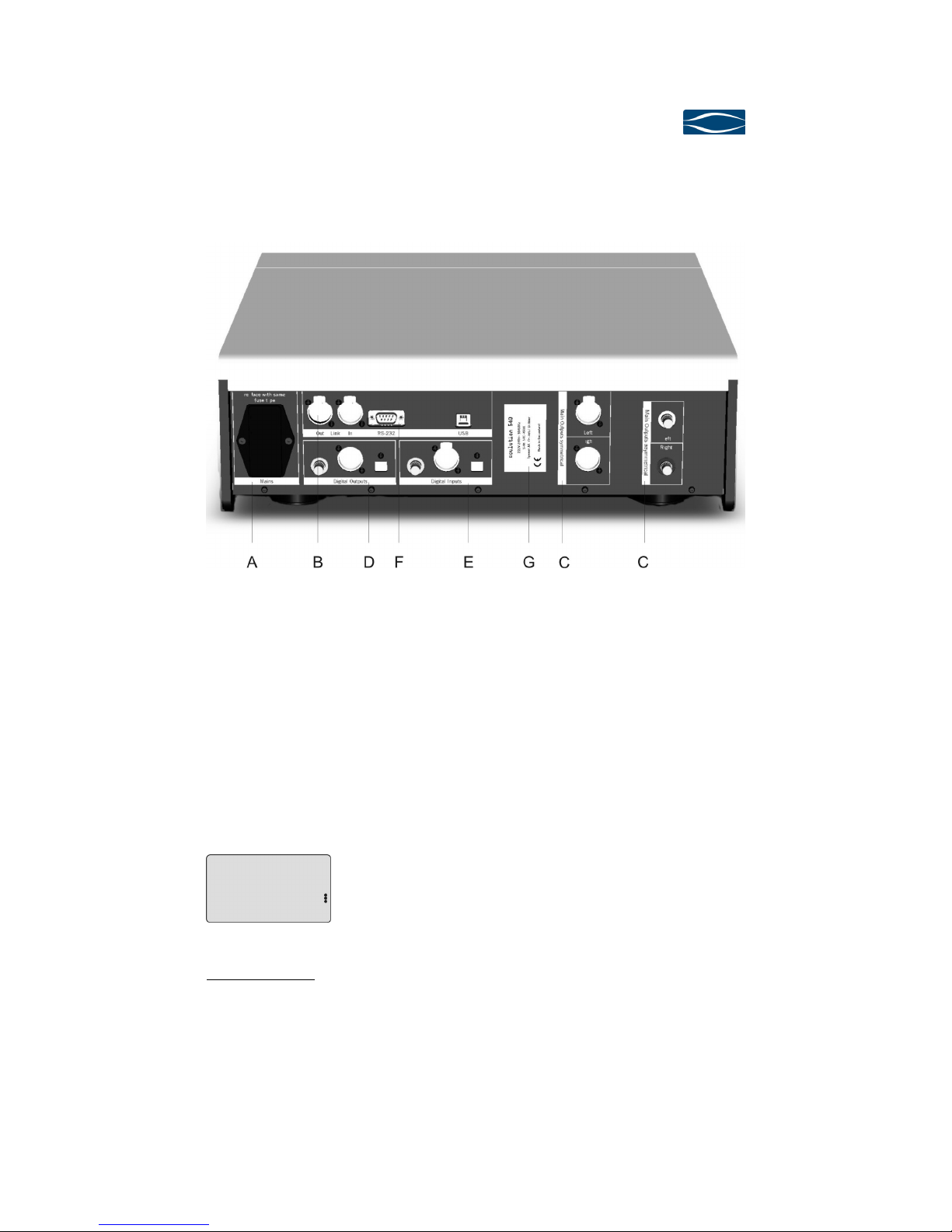
Rear panel of the Digital-Players 540
4.3.1
4.3.14.3.1
4.3.1 Mains
MainsMains
Mains (A)
(A) (A)
(A)
Connect the Digital-Player 540 with the mains. The enclosed power cord is opti-
mised for this application.
After switch-on of the Digital-Player 540 the standby power supply gets started. The
display shows "WAIT". Once constant conditions are reached, the Digital-Player 540
changes to operating condition OFF (red LEDs in display, power consumption <
0.5W).
Display in operating condi-
tion OFF
Security advice: Please follow the security advices on page 6!
Only switch-off the mains connection if your Digital-Player 540 is in operating
condition OFF.

soulution
nature of sound
Page 12
4.3.2
4.3.24.3.2
4.3.2 Link (B)
Link (B)Link (B)
Link (B)
The LINK-connection allows to control the switch-on of other soulution products or
to allow other soulution products to switch-on the Digital-Player 540. Connect the
LINIK-IN of the Digital-Player 540 for instance with the LINK-OUT of the Integrated
amplifier 530. Each soulution product has a LINK-OUT (Next Slave). This provides
the possibility of connecting all your soulution products. With the program-function
Start-Mode (see page 21) you can define the behaviour of the Digital-Player 540 af-
ter switch-on of the unit.
4.3.3
4.3.34.3.3
4.3.3 Main
MainMain
Main-
--
-Out (C)
Out (C)Out (C)
Out (C)
The Digital-Player 540 has balanced and unbalanced connectors for the main out-
put signal. Connect the output terminals with your (pre)amplifier. Due to the ex-
traordinary load-stability of the output-stage there are no restrictions regarding the
selection of the connecting cables. We recommend using balanced cables. For short
cable lengths also unbalanced cables represent a high uality connection, top ual-
ity cable and optimal layout prere uisite.
Security advice: Please follow the security advices on page 6!
Wrong cabling could damage your Digital-Player 540, your preamplifier, your ampli-
fier or your loudspeakers. Excessive volumes due to inappropriate handling may
cause hearing damages.
4.3.4
4.3.44.3.4
4.3.4 Digita
DigitaDigita
Digital
ll
l-
--
-Output (D)
Output (D)Output (D)
Output (D)
The Digital-Player 540 has 3 digital output connectors. (SPDIF (RCA), AES/EBU,
Toslink). Connect your favourite digital output with the digital input of your external
D/A-Converter. With the program-function
Digital-Out (chapter 5.2.9) the digital outputs can be (de)activated.
In Source-Mode CD the data from the mechanism are available at the outputs (no
signal for SCAD).
In Source-Mode DAC the digital data of the active digital input are transmitted to
the digital outputs. The data remains unchanged.
Digital
DigitalDigital
Digital-
--
-Player
PlayerPlayer
Player
540
540540
540
User manual
Page 13
Security advice: Please follow the security advices on page 6!
Wrong cabling could damage your Digital-Player 540, your preamplifier, your ampli-
fier or your loudspeakers. Excessive volumes due to inappropriate handling may
cause hearing damages.
4.3.5
4.3.54.3.5
4.3.5 Digital
DigitalDigital
Digital-
--
-Input (E)
Input (E)Input (E)
Input (E)
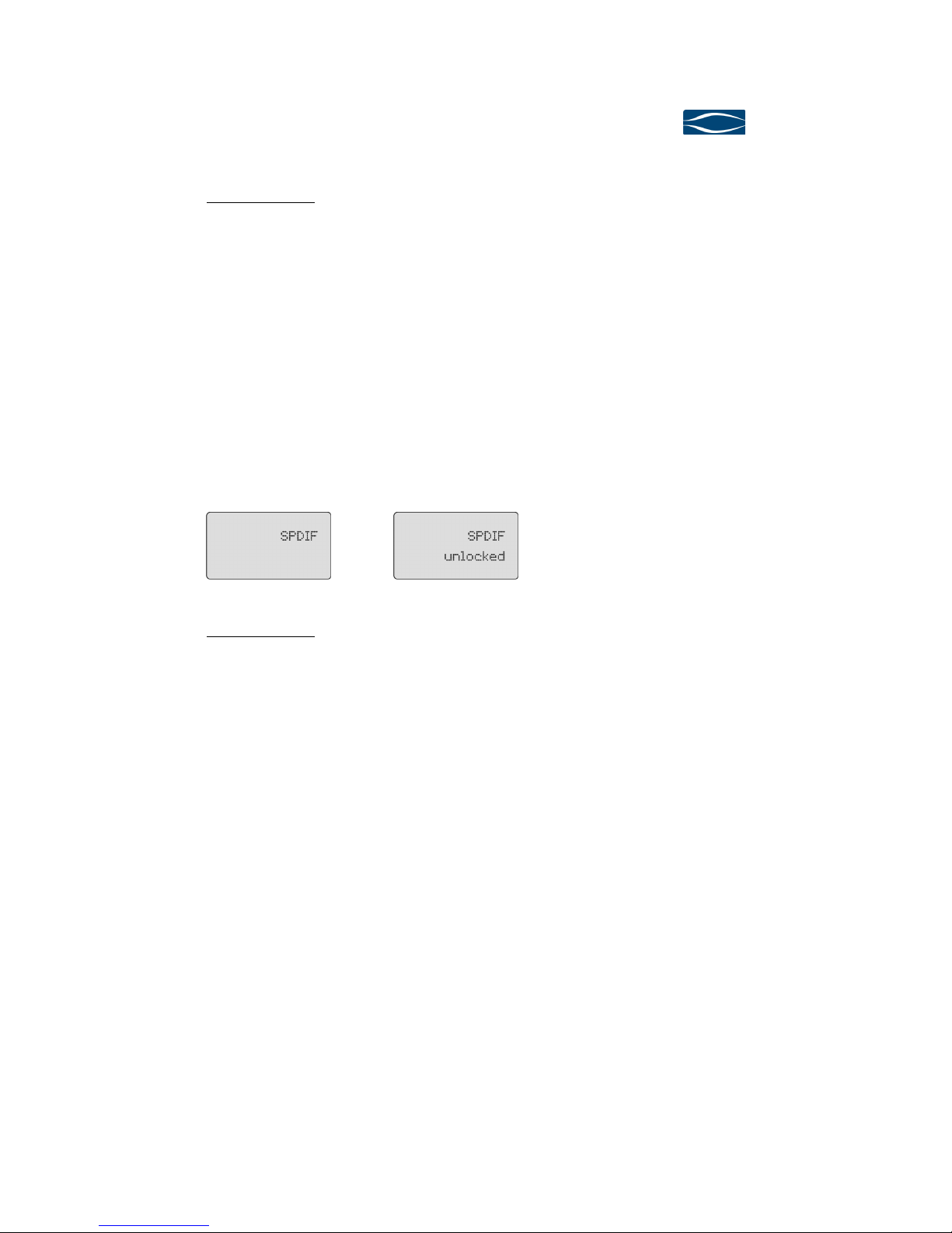
The Digital-Player 540 can receive external digital data from other digital sources.
The top class D/A-converter section and output-stage can thus be used for these
sources alike. It has four digital input connectors (SPDIF, AES/EBU, Toslink and
USB). The USB input can receive digital data up to 24Bit, 96kHz. The other inputs
receive digital data up until 24Bit, 192kHz.
Display für digitales Eingangs-
signal an SPDIF
Display bei Unterbruch des
digitalen Datenstroms
Security advice: Please follow the security advices on page 6!
Wrong cabling could damage your Digital-Player 540, your preamplifier, your ampli-
fier or your loudspeakers. Excessive volumes due to inappropriate handling may
cause hearing damages.
4.3.6
4.3.64.3.6
4.3.6 RS
RSRS
RS232
232 232
232 Interface
InterfaceInterface
Interface (F)
(F) (F)
(F)
The Digital-Player 540 can be remote controlled through the RS232 interface. All
functions can be controlled and relevant information is provided to the control unit.
4.3.7
4.3.74.3.7
4.3.7 Type label
Type label Type label
Type label (G)
(G)(G)
(G)
Please note the serial number of your Digital-Player 540 on page 7 of this user
manual. This allows you to have the specific data at hand without removing your
units from the HiFi rack.

soulution
nature of sound
Page 14
4.4
4.44.4
4.4 Front panel
Front panelFront panel
Front panel
of the Digital
of the Digitalof the Digital
of the Digital-
--
-Player
PlayerPlayer
Player 540
540 540
540
Front panel of the Digital-Player 540
4.4.1
4.4.14.4.1
4.4.1 Power (H)
Power (H)Power (H)
Power (H)
With the Power button you define the operating condition ON or OFF (red LEDs). In
operating condition OFF the audio circuits are completely disconnected from the
output terminal (Main-Out), the mechanism and the digital sections remain deacti-
vated. The Main-Out terminals are only activated if the Digital-Player 540 is ready
for operation and if no errors are present.
Display in operating condi-
tion OFF
Display while starting the
Digital-Player 540, Start-
Mode NORM.
Display in operating condi-
tion ON, no disc in mecha-
nism.
We suggest switching the Digital-Player 540 to operating condition OFF (power con-
sumption in < 0.5W) while not listening to music. Your Digital-Player 540 can eas-
ily be activated with the remote control.

Digital
DigitalDigital
Digital-
--
-Player
PlayerPlayer
Player
540
540540
540
User manual
Page 15
LINK-System:
In case the Digital-Player 540 switches on other soulution products with the LINK-
System it remains in MUTE until all connected components are switched on (Dis-
play LINK Connect).
If no errors have occurred while switching-on the other components the Digital-
Player 540 changes into operating condition ON.
Display in operating condi-
tion OFF (Standby)
Display during switch-on of
connected units
Display in operating condi-
tion ON
When the Digital-Player 540 is switched off all connected LINK components are
switched off simultaneously (operating condition OFF).
Display during switch-off of
connected units
Display in operating condi-
tion OFF
If an error occurs within a LINK-component while operating the display shows LINK
ERROR.
Display if an error occurs
with one of the connected
units
Security advice: Please follow the security advices on page 6!
Wrong cabling could damage your Digital-Player 540, your preamplifier, your ampli-
fier or your loudspeakers. Excessive volumes due to inappropriate handling may
cause hearing damages.
soulution
nature of sound
Page 16
4.4.2
4.4.24.4.2
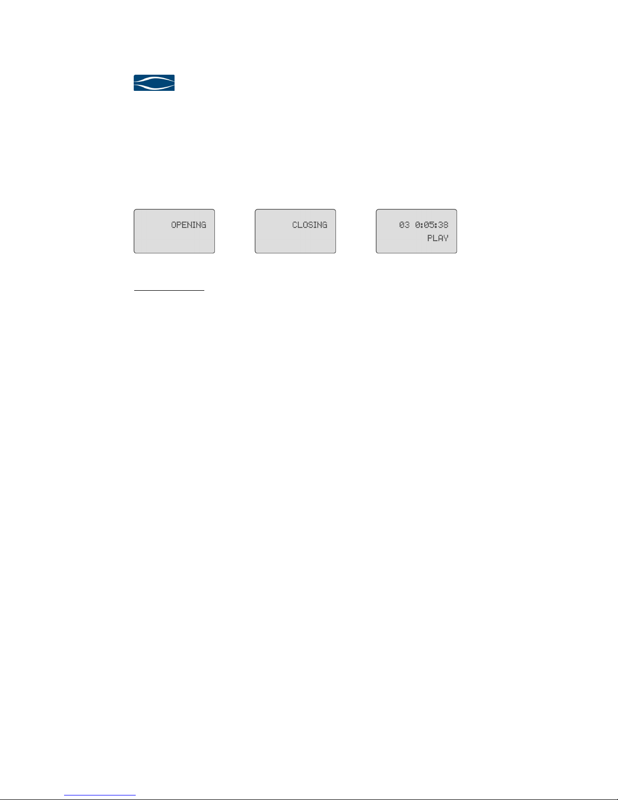
4.4.2 Open (I)
Open (I)Open (I)
Open (I)
The Open button opens or closes the drawer of the Digital-Player 540. If a CD/SACD
is playing the first push on the Open button will stop the mechanism, the second
push will open the drawer. In Source-Mode DAC the mechanism can not be opened.
Display while opening the
mechanism.
Display while closing the
drawer of the mechanism.
Display while playing a
CD/SACD.
Security advice: Never close the drawer by hand.
4.4.3
4.4.34.4.3
4.4.3 Prog (J)
Prog (J)Prog (J)
Prog (J)
The Prog button switches the Digital-Player 540 between operating-mode and pro-
gramming-mode. In the programming-mode you may adjust the Digital-Player 540
to your individual re uirements.
4.4.4
4.4.44.4.4
4.4.4 Select (K)
Select (K)Select (K)
Select (K)
The Select knob controls the functions Track select, Volume Control, Play/Pause,
Input-Select and is used for the Programming. The behaviour of the Select knob
changes depending on the activated Source-Mode.

Digital
DigitalDigital
Digital-
--
-Player
PlayerPlayer
Player
540
540540
540
User manual
Page 17
Source Mode: CD/SACD
Source Mode: CD/SACDSource Mode: CD/SACD
Source Mode: CD/SACD
Volume
VolumeVolume
Volume-
--
-Mode „ON“
Mode „ON“Mode „ON“
Mode „ON“
Volume
VolumeVolume
Volume-
--
-Mode „OFF“
Mode „OFF“Mode „OFF“
Mode „OFF“
Track select
(4.4.4.1) Track select
(4.4.4.1)
Play/Pause
(4.4.4.3) Play/Pause
(4.4.4.3)
Change to Volume-
Control-Mode no function
Volume-Control
(4.4.4.4) no function
Source
SourceSource
Source-
--
-Mode: DAC
Mode: DACMode: DAC
Mode: DAC
Volume
VolumeVolume
Volume-
--
-Mode „ON“
Mode „ON“Mode „ON“
Mode „ON“
Volume
VolumeVolume
Volume-
--
-Mode „OFF“
Mode „OFF“Mode „OFF“
Mode „OFF“
Input-Select
(4.4.4.2) Input-Select
(4.4.4.2)
Change to Volume-
Control-Mode no function
Volume-Control
(4.4.4.4) no function

soulution
nature of sound
Page 18
4.4.4.1
4.4.4.14.4.4.1
4.4.4.1 Track select
Track selectTrack select
Track select
Rotating the Select knob allows selecting a new track. Rotating to the right will in-
crease the track number, rotating to the left will decrease the track number. After 3
seconds the newly selected track will be played.
4.4.4.2
4.4.4.24.4.4.2
4.4.4.2 Input
InputInput
Input-
--
-Select
SelectSelect
Select
Rotating the Select knob allows selecting the digital input.
Display in D/A-Converter-
Mode for Input SPDIF
Display in DA-Converter
Mode for Input AES/EBU
4.4.4.3
4.4.4.34.4.4.3
4.4.4.3 Play/Pause
Play/PausePlay/Pause
Play/Pause
In Source-Mode CD/SACD pressing the Select knob for less than 0.5 seconds will
switch the Digital-Player 540 between Play and Pause. If the drawer is open while
pressing the Select knob for less than 0.5 seconds the drawer will be closed and the
Digital-Player 540 starts to play track 1 of the inserted CD/SACD.
Display while playing a
CD/SACD
Display for Pause
4.4.4.4
4.4.4.44.4.4.4
4.4.4.4 Volume
VolumeVolume
Volume Control
Control Control
Control
If the Volume-Mode has been activated, a long push on the select knob will bring
the Digital-Player 540 in Volume-Control-Mode. Rotating the select knob will
change the volume. After a timeout of approx. 3 seconds the Volume-Control-Mode
is deactivated. This ensures that the volume is changed only by purpose.
Table of contents
Other Solution Media Player manuals


