Sommer & Maca Industries VFE-4 User manual
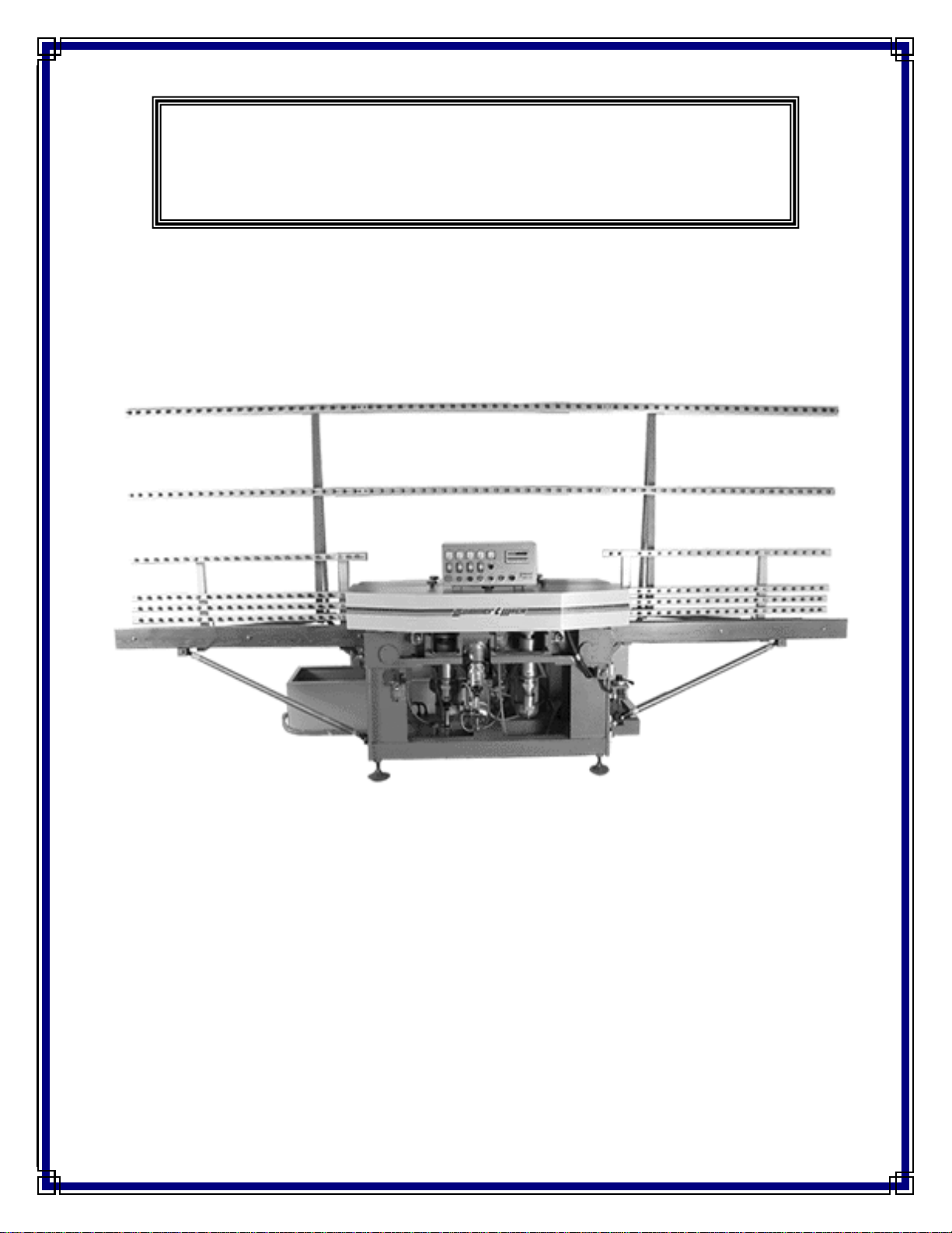
VFE-4
FOUR-CUP FLAT EDGER
5501 West Ogden Avenue
Cicero, Illinois 60804
Tel: (708). 863.5446 / (773). 242.2871
Fax: (708). 863.5462
ATLANTA / CICERO / COMMERCE / DALLAS / MOONACHIE/ SANTA CLARA
Sommer & Maca Industries, Inc.

WARRANTY STATEMENT
SOMMER & MACA Industries, Inc. (Seller) warrants products of its manufacture to be free from defects in
materials and workmanship in normal use for six months from the date of shipment unless a shorter period is
provided elsewhere in this document. Seller’s obligation and Buyer’s exclusive remedy shall be limited to the
repair or replacement at Seller’s option, of defective parts within warranty period, provided Buyer gives Seller
immediate written notice of such alleged defects, and if requested by Seller, returns the defective parts to
Seller’s factory for Seller’ inspection.
The warranties contained herein are in lieu of any other warranty expressed or implied, including any warranty
of MERCHANTABILITY OR FITNESS FOR PURPOSE.
In the case of equipment furnished by Seller but not of Seller’s manufacturer, Seller’s liability to Buyer
hereunder. Adjustment at the manufacturer thereof makes to Seller. Seller shall in no event be liable for
consequential damages.
Warranties hereunder shall not apply to any equipment that shall have been damaged by misuse, neglect, failure
to perform maintenance or accident after the shipment thereof by Seller. In addition thereto, this warranty shall
be null and void if:
1. Machine is used in a manner contrary to instruction or after malfunction is noticed.
2. Buyer does not honor terms of payment.
3. Machine is modified or altered without the agreement of Seller.

PREFIX
We suggest to carefully follow the instructions in this manual and to regularly follow procedures of
maintenance, which will allow you to obtain a higher degree of reliability, safety and durability of the product.
This manual contains several advises and precautions for safety. We urge you to read them carefully.
In this way you will avoid danger, injuries and eventual damage to the machine.
Exclusively trained personnel must do maintenance and repairs.

INDEX
1.) Technical features
1.1) Machine dimensions
1.2) Electrical and pneumatic requirements
1.3) Machine performance description
2.) Safety rules
2.1) General safety rules
3.) Shipping, movement and storage
3.1) Machine shipping and crating
3.2) Packing and unpacking
3.3) Storage until installation
4.) Installations and connections
4.1) Environmental working conditions
4.2) Space requirements
4.3) Machine installation requirements
4.4) Electrical connection
4.5) Pneumatic connection
5.) Equipment description
6.) Main assemblies
7.) Operation cycle: commands, functions and settings
7.1) Wheel replacement procedure
7.2) Necessary spacing between glass pieces
8.) Machine circuits
8.1) Electrical circuit
8.2) Electrical specifications
A. General electrical characteristics
B. Motors
8.3) Pneumatic arrangement
9.) Maintenance
9.1) Preventive maintenance
9.2) Fuse list
10.) Troubleshooting solutions
11.) Annexes

1.)
TECHNICAL FEATURES
1.1)
Machine dimensions
Length : 5000 mm (196.5”)
Width : 1300 mm (51”)
Total height : 2400 mm (94.5”)
Worktop height : 850 mm (33.5”)
Weight : 1300 Kg (2866.5 lbs)
1.2)
Electrical and pneumatic requirements
Voltage : 3-Phase/230Volts +/- 10%
Frequency : 60 Hz. +/-5%
Auxiliary service voltage : 24Volts/60Hz.
Pneumatic supply : 6 Bars (87 psi).
Installed power : 12 kW (16) hp +/- 10%
1.3)
Machine performance description
Workable thickness : 3 – 20 mm (1/8” - 3/4”)
Working speed : 0 – 3 m/min (0-9.84 ft/mn)
Adjustable removal : 0 – 2.5 mm (0 – 0.098”)
Coolant system : Closed circuit

2.)
SAFETY RULES
The machine is provided with all devices of protection both mechanical (chain guard, shelters, etc.) and
electrical (sensors, stops, etc.) in order to avoid any contact with moving parts by the operator.
It is absolutely prohibited for anyone to alter or remove any safety devices mentioned above with the
power on!!
Any kind of verification, control, cleaning, maintenance, change or substitution of parts must be done
with the power off and the main disconnect locked out. (see section 9)
The machine is moreover designed in conformity to CE as per the enclosed statement.
The manufacturer declines any and every responsibility for lack of following safety rules and of injury
prevention described below. He moreover declines every responsibility of damages caused by an improper use
of the equipment or changes made without authorization. It is also necessary for personal safety that no one
beside the operator remains in proximity of the equipment when in use.
2.1) General safety rules
When operating electric equipment, it is necessary to adopt the appropriate safety precautions to minimize the
risk of electrical shock or injuries. Before operating the machine, read the manual carefully and memorize the
following safety rules and save this booklet for future reference:
♦Keep the work area clean and orderly, as unorganized work areas encourage accidents.
♦Before starting, verify the condition of the machine. Check the standard operation and for broken and or
damaged parts. Replace all broken or damaged parts by a competent and authorized service person.
♦All repairs performed by unauthorized service personnel will void the warranty and will constitute operating
the equipment in an unsafe manner leading to potential danger.
♦It is absolutely prohibited to let children, outsiders, untrained, or people in poor health to touch or use this
equipment.
♦Verify that the electrical power source conforms to the electrical specifications before operating this
machine.
♦When installing the electrical power source, make sure that the machine is properly grounded.
♦Check the outlet to be appropriate and compatible with the automatic protection switch in the machine.
♦The extension cord if used must have a grounded receptacle, plug and cable as per code.
♦Never stop the machine by disconnecting the power.
♦Check periodically the condition of the cable and replace it should it become cut or frayed. This work is to
be performed only by qualified personnel.
♦Do not allow any personnel to come in contact with this cable.
♦Do not ignore these advices. Such an act will constitute an unsafe use of this equipment and will create a
potential danger.
♦Personnel authorized by the manufacturer must make repairs.
♦The manufacturer is available for immediate technical assistance to insure optimum performance and the
maximum production of the machine.

3.)
SHIPPING, MOVEMENT AND STORAGE
Specialized and competent personnel must perform all shipping operations of the machine.
3.1) The crated machine is easily transportable by a crane or a forklift with a minimum capacity of (3) tons
and lifting eyes as shown on the machine assembly drawing in the Annex 0 section of this manual.
Machine shipping and crating
In the act of moving be very careful to avoid bumping or dropping the machine or causing excessive
vibration to avoid damaging components.
3.2) After unpacking, make sure of the condition of the machine while checking to see if there is any visible
damage.
Packing and unpacking
If in doubt, do not use the machine and call the manufacturer’s customer’s service.
3.3) It is okay to store the machine in its original container providing that it is not stored in a place of high
humidity.
Storage until installation
In the case of a long or extended idle period or a period of nonuse after the machine has been used, it is
necessary to disconnect the power source and provide protection to the machine with a plastic cover to
avoid dust. Grease all parts that can be damaged by oxidation or moisture.

4.)
INSTALLATION AND CONNECTIONS
4.1) The machine can work at temperatures between 41 and 113 degrees Fahrenheit.
Environmental working conditions.
4.2) Make sure that the clearance provided around the machine is sufficient to be able to open all doors
completely and to perform all operations of maintenance.
Space requirements
4.3) Before placing the machine in its final location, proceed with the following checklist:
Machine installation requirements.
Check the ability of the floor to support the weight of the machine and its accessories.
Check the lighting around the machine. It should be free from shaded areas, inconvenient high
beams and or stroboscopic lights that could create dangerous conditions.
Check the condition of the machine for damage as a result of transportation.
Check to see that all feet of the machine are uniformly positioned on the floor.
After the machine has been placed in its working position, it must be correctly leveled using the
adjustable feet.
4.4) Work performed on electrical parts, electrical safety of this equipment is assured only when it is
correctly connected and properly grounded as per federal, state, and local codes concerning the same.
Electrical connection
It is mandatory to verify these basic safety requirements and when in doubt, ask for a check of the
electrical circuit by professionally trained personnel.
The manufacturer is not responsible for damages caused by an improperly connected machine.
WARNING: Interruption capacity of main circuit breaker: < 6 kA
Verify that the short circuit capacity of the supply is compatible
With the main circuit breaker.
4.5) Compressed air is required and must be connected to the FRL (filter, regulator and lubricator) on the
outside of the machine.
Pneumatic connection
A shut off valve should be placed ahead of the FRL.
After pressurizing the pneumatic circuit, set the air pressure on the pressure gauge of the regulator to 6
bars which is approximately 90-psi minimum. Adjust the knob on the regulator to achieve the above
value.

5.)
EQUIPMENT DESCRIPTION
There are four spindles equipped with:
•1st
•2
diamond grinding wheel – 150 mm dia. (M1)
nd
•3
grinding wheel for rear arris – 100 mm dia. (M2)
rd
•4
grinding wheel for front arris – 100 mm dia. (M3)
th
polishing wheel for flat edge – 150 mm dia. (M4)
The diamond grinding wheel spindle M1 have a locknut and a knurled knob (see enclosed drawing MMD on
annex 4). One complete turn of the knob #3 on the drawing MMD will raise or lower the grinding wheel by 2
mm or approximately .079”. This knob has 40 grades; each grade is equal to variation of height of .002”.
The spindles for the arris edges and the flat polishing wheels work pneumatically, and are controlled
electronically to engage and disengage the operation of the electrovalves relative to every wheel.

6.)
MAIN ASSEMBLIES
1) Lever to regulate glass removal
2) Dial indicator for reading of quantity to be removed
3) Adjustable feet to level the machine
4) Knurled knob for diamond grinding wheel adjustment
5) Diamond grinding wheel motor M1
6) Rear arris grinding wheel motor M2
7) Front arris grinding wheel motor M3
8) Polish wheel motor M4
9) Pneumatic cylinder
10) FRL group (filter, regulator and lubricator)
11) Base
12) Conveyor motor to advance glass
13) Anchors to lift and move the machine
14) Support structure
15) Control panel (see annex. #1)

7.)
OPERATION CYCLE: COMMANDS AND FUNCTIONS
The machine operator is advised to do the following:
Warning:
Always make sure the pump is ON, before you run glass. Otherwise a major damage could be caused
to the machine.
The switching on of the spindles must be done progressively as follows:
1. Turn motor M1 on (diamond grinding wheel).
2. Turn motor M2 on (rear arris grinding wheel)
Note: The pump will be turned on automatically when you turn on M1
3. Turn motor M3 on (front arris grinding wheel)
4. Turn motor M4 on (regular flat polishing wheel)
WHEELS GRIT PART#
M1 140-170 (.025inch DEEP) 3-97302-01
M2 3-97301-02
M3 3-97301-02
M4 3-97300-01
AB 280 CUP
10S40
TYPE
FOUR CUP MACHINE WHEELS ARRANGEMENT
FLAT EDGE CUP (DIAMOND)
AB 280 CUP
The adjustment of the amount of glass to be removed is located under the infeed glass conveyor side and is
changed by operating the lever (0 – 0.4”) as seen on the decimal dial indicator.
NOTE THAT MAXIMUM
MATERIAL REMOVAL IS 0.098” (3/32”)
For optimum machine output, it is recommended to use these settings.
mm 4 TO 8 8 TO 12 12 TO 20
inches 1/8 TO 5/16 5/16 TO 1/2 1/2 TO 3/4
bars 2 2 2
psi 29 29 29
bars 3.5 3.5 TO 4.5 4.5 TO 5
psi 51 51 TO 66 66 TO 73
m/mn 1.4 TO 1.8 1.3 TO 1.6 0.5 TO 0.8
ft/mn 4.6 TO 5.9 4.26 TO 5.25 1.64 TO 2.62
CONVEYOR SPEED
SPINDLE 2 & 3
AIR CYLINDER PRESSURE
GLASS THICKNESS
WHEELS #2, #3 & #4 SETTING
SPINDLE 4
AIR CYLINDER PRESSURE
NOTES:
1- ONLY METRIC CONVEYOR SPEED CAN BE ENTERED INTO CONTROL PANEL
2-MINIMUM PRESSURE ON ALL CYLINDERS SHOULD BE 2 BARS
3- LOWER PRESSURE ON M4 WHEN POLISHING SMALL TAIL STOCK

7.1)
Wheel replacement procedure
When replacing grinding or polish wheels, insert spindle-locking wrench over the flats on the spindle hub. Place
30mm box wrench or 8mm Allen wrench on the spindle locking screw, hold firm and rotate the spindle
clockwise. This will loosen locking screw. Reverse hub rotation to tighten locking screw.
In the event you must replace the diamond grinding, proceed as follows:
•Lower the diamond-grinding wheel via the knurled knob as far as possible while leaving the locknut in its
previous position.
•Remove the old wheel as mentioned above
•Install the new wheel
•Turn water on
•Turn motor M1 on if you working on spindle 1
•Adjust conveyor speed to minimum level
•Load a piece of glass into the machine
•Set the conveyor direction switch to forward
•Press the conveyor start button
•Wait until glass passes the grinding wheel, and set the conveyor direction switch to forward
•Remove glass and measure the amount of glass removed
•Raise the knurled knob until the desired amount of glass is removed and retighten locknut
•Gradually increase the glass conveyor speed to its desired level
In the event of glass breakage, press the emergency stop button
•Decrease speed control setting and remove the glass from the machine by reversing the glass travel
direction.
•Correct the problem causing the breakage and resume operation.
7.2)
Necessary spacing between glass pieces
•Leave 1 inch in between glass pieces of same thickness, so you can put your fingers between the two glass
pieces to remove it from glass conveyor.
•Leave 8 inches in between glass pieces of different thickness, because that is the necessary distance for
arris and polish spindle to retract and engage.

8.)
MACHINE CIRCUITS
8.1)
♦Schematic and components annex #2
Electric circuit
♦Control panel annex #1
8.2)
Electrical specification
A) General electrical characteristics
Machine voltage : 3 phase/230 volts +/-10%
Frequency of operation : 60 Hz +/-5%
Auxiliary service voltage : 24 volts/60 Hz
Pneumatic service voltage : 24 volts/60 Hz
B) Motors
Motor M1 : 2 pole/380 volts/60 Hz/3 hp
Motor M2 : 2 pole/380 volts/60 Hz/2 hp
Motor M3 : 2 pole/380 volts/60 Hz/2 hp
Motor M4 : 2 pole/380 volts/60 Hz/3 hp
Pump motor : 2 pole/380 volts/60 Hz/0.5 hp
Conveyor motor : 4 pole/380 volts/60 Hz/0.5 hp
Complete with 160:1 reducer
8.3)
♦Pneumatic circuit outline Annex #3
Pneumatic arrangement

9.)
MAINTENANCE
WARNING!
Any kind of verification, cleaning, maintenance, replacement and substitution of parts must be performed
with the power off and the main disconnect locked out. (see section 2)
9-1.) Preventive maintenance
•When switching the machine on, check the air pressure. It must be at or above 6 bars / 90psi.
•It is necessary to keep the machine clean from glass grindings regularly to prevent premature wear.
•It is also necessary to keep the machine inside of the spindle tub clean from broken glass to prevent damage
to the water delivery system.
•It is necessary to continually check the condition of the grinding and polishing wheels and replace them as
required.
•Every 40 hours of operation drain the condensation from the FRL group. Replenish oil reservoir with a good
grade of Air Tool Oil (Mobil Almo 525 or equivalent). P/N 299-0148-0
•Every 200 hours of operation lubricate all of the ball bearing units with a NLGI #2 wheel bearing grease.
9-2.) Fuse list
Somaca
VFE 4
Vendor
Part Number
Fuse ID
Description
Vendor
Part Number
Qty
4700302002
4FU1
FUSE 1A 400V 10x38mm 120ka
Shawmut
16011-G
2
4700330102
4FU2
FUSE 6A 500V 10x38mm 120ka
Shawmut
16523-G
1
4700302001
3FU1
FUSE 4A 400V 10x38mm 120ka
Shawmut
16019-G
2
4700330103
1FU1
FUSE 32A 400V 10.3x38mm 100ka
Shawmut
16043-G
3
4700302004
1FUG
FUSE 50A 400V 14x51mm 100ka
Shawmut
17551-G
3
OSHA 29 CFR 1910.147 standard requires the placement of a
lockout on energy stored equipment in a manner that will
render them safe to work on and prevent the inadvertent start
up of such equipment, in accordance with an established
procedure, and ensure that the energy-isolating device and
the equipment being controlled cannot be operated, while it
is being serviced or maintained, until the lockout device is
removed.

10.)
TROUBLE SHOOTING SOLUTIONS
PROBLEM CAUSE
SOLUTION
Motors do not spin Burnt fuse Replace
Thermal out Reset
Electrical interruption Verify
No pneumatic movement Not enough air pressure Verify pressure
At 6 bars / 90 psi. Minimum
Solenoid valve broken Check and replace
or defective
Water pump not working Burnt fuse Replace
Thermal out Reset
Electrical interruption Verify

11.)
ANNEXES
Main Assembly Annex#0
Control panel Annex #1
Electrical circuit outline Annex #2
Pneumatic circuit outline Annex #3
Assemblies Annex #4
Programming of “Mini-Job” Controller Annex #5

ANNEX #0


ANNEX #1

Table of contents
Other Sommer & Maca Industries Industrial Equipment manuals


