manuals.online logo
Brands
  1. Home
  2. •
  3. Brands
  4. •
  5. Zimmer
  6. •
  7. Industrial Equipment
  8. •
  9. Zimmer SPN User manual

Zimmer SPN User manual

Zimmer GmbH ● Im Salmenkopf 5 ● 77866 Rheinau ● Germany ●+49 7844 9138 0 ● +49 7844 9138 80 ● www.zimmer-group.com
INSTALLATION AND OPERATING INSTRUCTIONS: Zero-point clamping system, pneumatic, SPN series
Installation and Im Salmenkopf 5
operating
instructions 77866 Rheinau
SPN series Germany
DDOC00836 +49 7844 9138 0
Index c [email protected]
EN 2021-12-09 www.zimmer-group.com
1. Supporting documents
NOTICE
Read through the installation and operating instructions before installing or working with the product.
The installation and operating instructions contain important notes for your personal safety. They must be read
and understood by all persons who work with or handle the product during any phase of the product lifetime. The
documents listed below are available for download on our website www.zimmer-group.com:
• Catalogs, drawings, CAD data, performance data, technical data sheets
• Information on accessories
• Detailed installation and operating instructions
• General Terms and Conditions with specications for the warranty entitlement
ÖOnly the documents currently available on the website are valid.
In these installation and operating instructions, "product" refers to the product designation.
2. Safety notices
WARNING
Risk of injury during manual loading
Risk of injury due to parts moving independently after the power supply has failed or is switched off (including an
emergency stop).
►Do not reach into the product.
►Do not reach between the clamping surfaces.
►Wait for the system to come to a complete standstill.
Risk of injury due to parts moving independently after accidental or careless actuation of the "release actuation."
►Do not insert a clamping pin into a clamped product.
►Do not place a clamping pin onto a clamped product.
Risk of injury from parts ying and being ung
Various components of the product are continuously under spring tension.
• Spring package
• Cover
►Do not loosen the screws of the cover.
►Do not remove the cover.
ÖWarranty and disclaimer
CAUTION
Injuries or malfunctions can occur, especially with:
• Crushing during installation due to an unsecured mounting piece
• Improperly assembled electrical connections
• Power supply faults, e.g. due to pressure uctuations
• Damaged or loose power lines
• Missing or loose fastening screws
• Failure to switch off the working medium during assembly or repair work on the product
• Human error
• Failure to observe the safety and warning notices during installation and commissioning
• Failure to observe the safety regulations for operating the machine into which the product is to be installed
3. Proper use
NOTICE
The product is only to be used in its original state with its original accessories, with no unauthorized changes and
within the stipulated parameter limits and operating conditions. Any other or secondary use is deemed improper.
►Operate the product only in compliance with the associated installation and operating instructions.
►Operate the product only when it is in a technical condition that corresponds to the guaranteed parameters and
operating conditions.
ÖZimmer GmbH shall accept no liability for any damage caused by improper use. The operator bears sole respon-
sibility.
The product is used exclusively for positioning and clamping workpieces, clamping pallets or other clamping devices on tooling
machines or other suitable technical equipment. The product is designed exclusively for pneumatic operation. Use compressed
air in accordance with DIN ISO 8573-1 [4:4:4].
The product is designed for use in commercial or industrial applications.
For questions regarding use outside of the stipulated parameters, please contact Zimmer Customer Service.
Improper use occurs when the product is used in rotary applications without consulting Zimmer GmbH and the following
parameters are exceeded:
• Speed: 1500 rpm
• Peripheral speed: 35 m/s, relative to the center axis of the product
4. Personnel qualication
Installation, commissioning and maintenance may only be performed by trained specialists. These persons must have read and
understood the installation and operating instructions in full.
5. Product description
5.1 Forces and torques
INFORMATION
For information on the forces and torques for the following product, please refer to our website
www.zimmer-group.com:
Please contact Zimmer Customer Service if you have any questions.
5.2 Type plate
There is a laser engraving in the housing of the product.
The laser engraving contains the article number dl and conrmation
number dm.
dl
dm
INFORMATION
Please state the conrmation number dm in the event of damage or a complaint.
Please contact Zimmer Customer Service if you have any questions.
5.3 Functional description
The pneumatically operated product is designed for clamping workpieces and workpiece-clamping devices with extremely high
repeatability. Due to its structural design, the system is clamped without pneumatic pressure applied.
The clamping force can be signicantly increased by using an additional impulse on the PLUS connection. The form-t arrest
cannot be released until the release connection is actuated, the clamp dog is pressurized and the PLUS connection is simulta-
neously vented.
The product is optimally adapted to the clamping contour of the clamping pin. The resulting surface contact creates an
extremely rigid system that can absorb high forces and torques.
The basic version features two rotation prevention devices.
The blow-out or cleaning function prevents dirt or liquid from collecting in the pin holder and contact surface. When clamped,
the seal on the contact surface prevents dirt or liquids from penetrating into the product.
Safe operation can be veried by the following statuses by means of piston position sensing and a positioning check:
• Product opened
• Product closed (clamping pin clamped)
• Product closed (no clamping pin present)
• Workpiece present (rests upon the contact surface)
All functions can be controlled directly by means of the contact surface and the standard connections with O-rings. There is also
the option to control the product by means of alternative connections on the bottom of the product.
5.4 Product design
Pneumatic connections 6Rotation prevention
1Unlocking 7Fastening screw of the product
2PLUS connection 8Standard: Tubeless connection
3Blowing out/cleaning/positioning check 9Alternatively: Hose connection
4Sensing: Product opened bl Clamp segment
5Sensing: Product closed bm Spring package
bn Sealing support
bo Borehole for position checking
bp Pin opening
bq Cover
6
6
bn
7
bp
bo
bq
bm
bl
2
3
5
4
1
9
8
Fig. 1: SPN series Fig. 2: Cutaway view of the SPN series Fig. 3: Pneumatic connections of the SPN
series
6. Accessories
NOTICE
Before installing an accessory, make sure it is suitable for use with the selected variant. For information on all
available accessories, please visit our website.
Please contact Zimmer Customer Service if you have any questions.
7. Technical data
INFORMATION
For technical data, please visit our website.
This data varies within the series, depending on the specic design.
Please contact Zimmer Customer Service if you have any questions.
8. Installation
WARNING
Risk of injury due to uncontrolled movement
Risk of injury in case of uncontrolled movement of the machine or system into which the product is to be installed.
►Switch off the power supply of the machine before all work.
►Secure the machine's power supply against being switched on unintentionally.
►Check the machine for any residual energy that may be present.
Risk of injury in the event of uncontrolled movement of parts when the power supply is connected.
►Switch off the power supply to the product before all work.
►Secure the power supply against being switched on unintentionally.
►Check the product for any residual energy that may be present.
NOTICE
►Switch off the power supply before any assembly, installation or maintenance work.
The product must be mounted on a suitable mounting piece (made of steel).
ÖTo install the product, please refer to the detailed installation plan on our website or contact Zimmer Customer Service.
• Mount the product to the mounting piece from above using the installation holes.
• Fastening screws 7and cover caps cl are included in the scope of delivery (included loose).
• Strength class of the 10.9 fastening screws (DIN EN ISO 4762)
• Comply with the tightening torques of the mounting screws.
ÖZimmer GmbH recommends verifying the permitted load-carrying capacity of the required screw connections in accordance
with VDI 2230.
• You can nd the exact installation positions in the technical datasheet on our website.
• Check the product for possible transport damage before assembly.
• Recommendation: As a principle, only use tested compressed air hoses.
• Seal unused pneumatic connections.
8.1 Installing the mechanical system
The product is installed onto the mounting piece via the ange surface
and the fastening screws7.
The following work steps must be observed during installation:
ÖIf the PLUS connection2 is not in use, insert a lter cm into the
connection (lter included loose).
ÖThe lter cm must be ush with the bottom of the product during
installation.
►Insert the O-rings cp.
ÖLubricate the O-rings.
►Insert the product into the intended position on the mounting
piece.
ÖMake sure that the standard connections for the tubeless
connection are positioned correctly.
►Manually screw the fastening screws7into the thread until the
product is in contact.
ÖInsert the straight pin for the rotation prevention6if this is
required!
►Tighten the fastening screws 7with the corresponding tightening
torque.
ÖThe vent holes and lters have to be atmospherically vented over
their entire cross-section and protected against liquids (e.g. oil,
grease, etc.) and chips.
►Attach the cover caps cl.
cl
7
cm
2
cp
cp
cp
cp
3
5
4
1
Zimmer GmbH ● Im Salmenkopf 5 ● 77866 Rheinau ● Germany ●+49 7844 9138 0 ● +49 7844 9138 80 ● www.zimmer-group.com
INSTALLATION AND OPERATING INSTRUCTIONS: Zero-point clamping system, pneumatic, SPN series
Installation and Im Salmenkopf 5
operating
instructions 77866 Rheinau
SPN series Germany
DDOC00836 +49 7844 9138 0
Index c [email protected]
EN 2021-12-09 www.zimmer-group.com
8.2 Installing alternative hose connections
The following work steps must be observed when installing the power
supplies:
►Unscrew the grub screws cn.
►Insert the O-rings cp.
ÖLubricate the O-rings.
►Screw the pneumatic connections co into the alternative
connections.
ÖIf the PLUS connection2 is not in use, insert a lter cm into the
connection (lter included loose).
ÖThe lter cm must be ush with the bottom of the product during
installation.
ÖIf the standard connections are to replace the alternative
connections, the alternative connections must be tightly sealed.
co
cn
cm
8.3 Checking operational readiness
After the product has been properly installed, the following properties must be checked to verify that it is ready to be operated:
• Check pneumatic connections for leaks by looking and listening
• Check all fastening screws for their prescribed tightening torque
• Check the product for leaks while it is pressurized by looking and listening
8.4 Disassembly
Removal is carried out in the reverse order of that described in Section „Montage Mechanik“.
9. Operation
During machining, the entire contact surface of the zero-point clamping system must be covered so that no dirt can penetrate.
►Before any clamping, thoroughly clean the contact surfaces between the zero-point clamping system, the clamping pin and
the material to be clamped.
►Protect the pin hole from dirt when the product is not in use.
►To do this, use accessories such as the sealing pin or automatic seal.
►During operation, secure the zero-point clamping system against unintentional loosening.
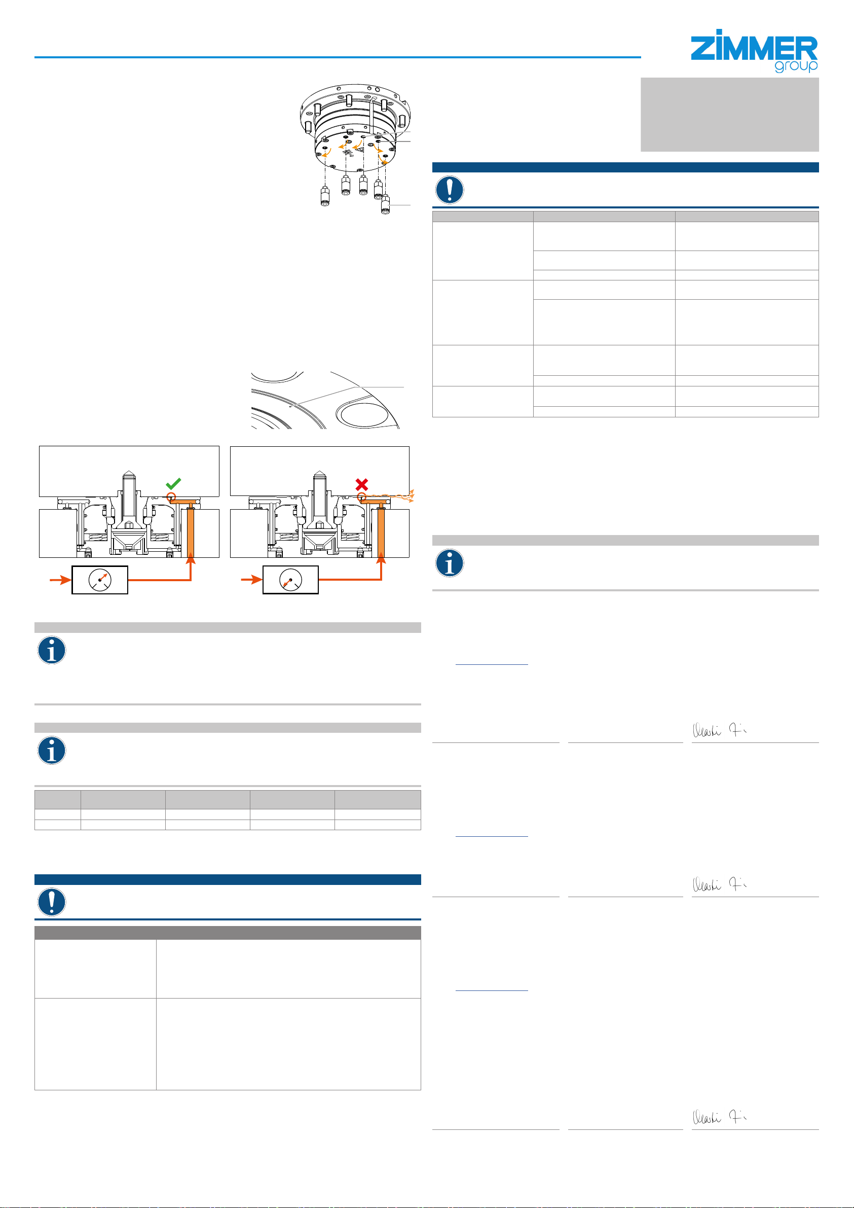
9.1 Positioning check
The product enables the testing or monitoring of the support using an
externally connected ow meter or dynamic pressure indicator.
This inspection veries that the workpiece or clamping plate is
correctly supported on the product.
The ow or dynamic pressure is measured by means of the
designated borehole boin the housing.
bo
ÖThe following illustrations depict an example of dynamic pressure sensing.
P
0 10
bar
P
0 10
bar
The clamped product is resting correctly on the contact surface.
ÖThis generates dynamic pressure.
The clamped product is not resting correctly on the contact
surface.
ÖNo dynamic pressure is generated (leakage).
INFORMATION
The operator of the product has sole responsibility for the positioning check. Sensing for the positioning check
is performed by means of an external ow meter or dynamic pressure indicator. The entire contact surface of the
product must be covered to ensure correct sensing during the positioning check.
Operating pressure for the positioning check: 1.5 bar
To use this function, an adjustable pressure switch must be connected upstream. This reduces the operating
pressure to the required 1.5 bar.
ÖThe power supply line is for blowing out, cleaning and the positioning check.
Please contact Zimmer Customer Service if you have any questions.
9.2 Piston position sensor
INFORMATION
The operator of the product has sole responsibility for piston position sensing. Sensing is performed by means of an
external ow meter or dynamic pressure indicator.
The entire contact surface of the product must be covered to ensure correct sensing during the piston position
sensing.
Operating pressure for piston position sensing: 1.5 bar
Please contact Zimmer Customer Service if you have any questions.
Connection Operating pressure [bar] Product unlocked Pin clamped Product closed/no pin
present
4 1 to 1.5 0 1 1
5 1 to 1.5 1 0 1
0 = dynamic pressure 1 = ow
10. Maintenance
The maintenance interval depends on the respective application. The higher the strain, the more frequently maintenance must
be carried out.
NOTICE
In case of visible damage or signs of malfunction, the zero-point clamping system must be taken out of operation
immediately. Do not start the product again until the damage has been repaired.
►Replace any worn components.
Interval Maintenance work
After 10,000 cycles or every 3 weeks Visual inspection
The visual inspection merely involves visually inspecting component parts and their
function. If any irregularities or damage are identied during the visual inspection, a
more detailed check of the component parts must be carried out.
►Carry out a visual inspection.
►Clean the product if it is dirty.
After 50,000 cycles or every year Measure the clamping force
►Measure the clamping force.
• Suitable devices for measuring the clamping force are available as
accessories.
ÖClamping force undershot by less than 15%
• Further use at the customer's discretion.
• Or have Zimmer GmbH perform the check.
ÖClamping force undershot by more than 15%
• Have Zimmer GmbH perform the check.
Dismantling and reassembling the product without authorization may result in complications, as special installation equipment is
required in some cases. Zimmer GmbH accepts no liability for any resulting malfunctions or damage.
11. Troubleshooting
NOTICE
For error-free function of the product, it is necessary that the contact surface is always completely covered.
►This prevents dirt from penetrating the system and causing malfunctions.
Error/fault Possible cause Measure
Product does not open
• Operating pressure is too low
• Leakage/blockage/pinching of the power
supply lines
►Increase operating pressure (4 to 6 bar)
►Check power supply lines
• Excess force is acting upon the centering
pin
►Reduce the tensile load or compressive
load on the product.
• Clamp dog does not move ►Vent the PLUS connection
Long response time (too little
air is fed in)
• Valve is too small (product opens after a
delay) ►Choose a larger valve accordingly
• Power supply lines from the valve to the
product are too long (product opens after
a delay)
►Shorten the power supply lines (keep the
distance from the product to the valve as
short as possible).
►Enlarge the cross-section of the power
supply lines.
Air leak or blow-off noise
• Housing parts are leaky (O-rings not tted
correctly)
• Installation error
►Align/mount the product again.
►Check the O-rings.
►Open/close the product several times.
• Connecting cables are leaky. ►Check power supply lines.
Dimensional deviations/chatter
marks
• Centering pin is not correctly retracted.
• Contamination of the product ►Clean the product.
• Product worn ►Completely replace the product.
12. Transportation/storage/preservation
►The product must be transported and stored only in the original packaging.
►If the product has already been installed on the superordinate machine unit, care must be taken during transport to ensure
that no unintentional movements can occur. Before commissioning and after transport, check all power connections and all
mechanical connections.
►If the product is stored for an extended period, the following points are to be observed:
ÖKeep the storage location as dust-free and dry as possible.
►Clean all components. There must be no dirt left on the components.
►Seal pneumatic connections by using suitable covers.
►Observe the required temperature.
13. Decommissioning and disposal
INFORMATION
When the product reaches the end of its operational phase, it can be completely disassembled and disposed of.
Completely disconnect the product from the power supply. The product can be disassembled and properly disposed
of according to material groups.
When disposing of them, observe the locally applicable environmental regulations and codes and regulations for
disposal.
14. RoHS declaration
In terms of the EU Directive 2011/65/EU
Name and address of the manufacturer:
Zimmer GmbH
Im Salmenkopf 5, 77866 Rheinau, Germany
+49 7844 9138 0
+49 7844 9138 80
www.zimmer-group.com
We hereby declare that the incomplete machine described below
Product designation: Zero-point clamping system, pneumatic
Type designation: SPN series
conforms to the requirements of the directive in its design and the version we put on the market.
Michael Hoch Rheinau, Germany, 2020-03-31
Authorized representative for compiling
the relevant technical documents
(Place and date of issue) Martin Zimmer
(Legally binding signature)
Managing Partner
15. REACH declaration
In terms of the EU Regulation 1907/2006
Name and address of the manufacturer:
Zimmer GmbH
Im Salmenkopf 5, 77866 Rheinau, Germany
+49 7844 9138 0
+49 7844 9138 80
www.zimmer-group.com
REACH stands for Registration, Evaluation, Authorisation and Restriction of Chemicals.
A full declaration of REACH can be obtained from the manufacturer due to the duty to notify in accordance with Art. 33 of the
REACH regulation ("Duty to communicate information on substances in articles").
Michael Hoch Rheinau, Germany, 2020-03-31
Authorized representative for compiling
the relevant technical documents
(Place and date of issue) Martin Zimmer
(Legally binding signature)
Managing Partner
16. Declaration of Conformity
In terms of the EU Machinery Directive 2006/42/EC (Annex II 1 A)
Name and address of the manufacturer:
Zimmer GmbH
Im Salmenkopf 5, 77866 Rheinau, Germany
+49 7844 9138 0
+49 7844 9138 80
www.zimmer-group.com
We hereby declare that the following, identically constructed safety components
Product designation: Zero-point clamping system, pneumatic
Type designation: SPN series
conform to the requirements of the 2006/42/EC directive in their design and the version we put on the market.
The following harmonized standards have been used:
Basic health and safety requirements:
DIN EN ISO 12100:2011-03 Safety of machinery – General principles for design – Risk assessment and risk reduction
DIN EN ISO 13849-1/-2 Safety of machinery – Safety-related parts of control systems
EN 349:1993+A1:2008 Safety of machinery – Minimum gaps to avoid crushing of parts of the human body
A full list of applied standards can be obtained from the manufacturer.
Clemens Kimmig Rheinau, Germany, 4/30/2021
Authorized representative for compiling
the relevant technical documents
(Place and date of issue) Martin Zimmer
(Legally binding signature)
Managing Partner

This manual suits for next models

5

Other Zimmer Industrial Equipment manuals

Zimmer GPH8000 Series User manual

Zimmer

Zimmer GPH8000 Series User manual

Zimmer GEP5000 Series User manual

Zimmer

Zimmer GEP5000 Series User manual

Zimmer HRC-01 Series User manual

Zimmer

Zimmer HRC-01 Series User manual

Zimmer SWM1000 Series User manual

Zimmer

Zimmer SWM1000 Series User manual

Zimmer MGH8000 User manual

Zimmer

Zimmer MGH8000 User manual

Zimmer HRC-07 Series User manual

Zimmer

Zimmer HRC-07 Series User manual

Zimmer AEPN1100-00-A User manual

Zimmer

Zimmer AEPN1100-00-A User manual

Zimmer MATCH LWR50L-27 Series User manual

Zimmer

Zimmer MATCH LWR50L-27 Series User manual

Zimmer SPN Series User manual

Zimmer

Zimmer SPN Series User manual

Zimmer GEP2000 Series User manual

Zimmer

Zimmer GEP2000 Series User manual

Zimmer GPD5000IL Series User manual

Zimmer

Zimmer GPD5000IL Series User manual

Zimmer GPP5000IL Series User manual

Zimmer

Zimmer GPP5000IL Series User manual

Zimmer A.T.S. 2000 User manual

Zimmer

Zimmer A.T.S. 2000 User manual

Zimmer EB5000 Series User manual

Zimmer

Zimmer EB5000 Series User manual

Zimmer GEP2000 Series User manual

Zimmer

Zimmer GEP2000 Series User manual

Zimmer GG4000 Series User manual

Zimmer

Zimmer GG4000 Series User manual

Zimmer GSI Series User manual

Zimmer

Zimmer GSI Series User manual

Zimmer PowerStop PHE16X10LSAK-A User manual

Zimmer

Zimmer PowerStop PHE16X10LSAK-A User manual

Zimmer LKE Series User manual

Zimmer

Zimmer LKE Series User manual

Zimmer MATCH LWR50F User manual

Zimmer

Zimmer MATCH LWR50F User manual

Zimmer DKHS1000 Series User manual

Zimmer

Zimmer DKHS1000 Series User manual

Zimmer GEH6000IL Series User manual

Zimmer

Zimmer GEH6000IL Series User manual

Zimmer MATCH LWR50L-25 Series User manual

Zimmer

Zimmer MATCH LWR50L-25 Series User manual

Zimmer GEP5000IL Series User manual

Zimmer

Zimmer GEP5000IL Series User manual

Popular Industrial Equipment manuals by other brands

IECHO PK-0604 user manual

IECHO

IECHO PK-0604 user manual

Siemens Maxum II manual

Siemens

Siemens Maxum II manual

Schmalz Mini Compact Ejector SCPMc operating instructions

Schmalz

Schmalz Mini Compact Ejector SCPMc operating instructions

Markem Imaje DigiConvert MC004-2014 P1082 operating instructions

Markem Imaje

Markem Imaje DigiConvert MC004-2014 P1082 operating instructions

Nidec RESCUE Select Pro manual

Nidec

Nidec RESCUE Select Pro manual

ABB ACH550-01 user manual

ABB

ABB ACH550-01 user manual

Thomas 7175 user guide

Thomas

Thomas 7175 user guide

WEIHONG NK300CX quick start guide

WEIHONG

WEIHONG NK300CX quick start guide

Grundfos NBE Series Installation and operating instructions

Grundfos

Grundfos NBE Series Installation and operating instructions

ITW Gema EasySelect-Cup Operating instructions and spare parts list

ITW Gema

ITW Gema EasySelect-Cup Operating instructions and spare parts list

turck TN-IOL2 Series Instructions for use

turck

turck TN-IOL2 Series Instructions for use

Giacomini KLIMAdomotic KPM45Y002 quick start guide

Giacomini

Giacomini KLIMAdomotic KPM45Y002 quick start guide

Aerotech ABRX Hardware manual

Aerotech

Aerotech ABRX Hardware manual

SkyAzúl 210 Installation & operation manual

SkyAzúl

SkyAzúl 210 Installation & operation manual

SMW Autoblok ZHVD-SZ instruction manual

SMW Autoblok

SMW Autoblok ZHVD-SZ instruction manual

Amada EMZ-3510NT Operator's manual

Amada

Amada EMZ-3510NT Operator's manual

ABB HT569226 Operation manual

ABB

ABB HT569226 Operation manual

Gilson SS-20 operating manual

Gilson

Gilson SS-20 operating manual

manuals.online logo
manuals.online logoBrands
  • About & Mission
  • Contact us
  • Privacy Policy
  • Terms and Conditions

Copyright 2025 Manuals.Online. All Rights Reserved.