Somnus DM18 APAP User manual

Somnus®DM18 APAP
CPAP Ventilator
User Manual
i
Preface
Thank you for purchasing the ventilator manufactured by Dymind Biotech.
Read and understand the entire user manual before operating this device. Store this user manual
properly for future reference.
Product name: CPAP Ventilator
Model: DM18 APAP
Safety classification: class II, type BF protection against electric shock
Contact Info for After-Sales Services
Manufacturer: Shenzhen Dymind Biotechnology Co., Ltd.
Address: 2/F, Nanfeng Building B, Nanshan Yungu Innovation Industrial Park, No.1183, Liuxian Blvd,
Taoyuan Street, Nanshan District, Shenzhen 518055, P.R.China
European Representative: 5 Bankside, Hanborough Business Park, Witney Ox29 8LJ UK
Service Tel: 400-998-7276
Tel: (86-755)26989825
Fax: (86-755)26746162
Website: http://www.dymind.com.cn/english/
Copyright
© Shenzhen Dymind Biotechnology Co., Ltd. All rights reserved. This document contains proprietary
information of Shenzhen Dymind Biotechnology Co., Ltd. (hereinafter referred to as Dymind Biotech).
No part of this document may be reproduced, copied, modified, disclosed, or transmitted in any form
or by any means without prior written consent of Dymind Biotech. This document is intended for
users of Dymind Biotech equipment, whom are authorized to use this document as they purchase
Dymind Biotech equipment. Unauthorized persons are not allowed to use this document.
All information in this document does not constitute a warranty of any kind, express or implied,
including, but not limited to, the implied warranties of merchantability and fitness for a particular
purpose. Every effort has been made in the preparation of this document to ensure accuracy of the
contents. However, Dymind Biotech assumes no liability or responsibility for any errors or omissions
in the contents of this document. Dymind Biotech reserves the right to improve any products to
enhance product reliability, functionality, or design.
®, ®, and Somnus®are trademarks of Dymind Biotech.

ii
Declaration
This user manual may be modified without notice.
Dymind Biotech reserves the right of final interpretation of this user manual.
The pictures in this user manual are indicative only. If there is inconsistency between the pictures
and the actual product, the actual product shall govern. Do not use the pictures for other than
intended use.
The continuous positive airway pressure (CPAP) ventilator manufactured Dymind Biotech has
passed strict clinical test and obtained the national medical equipment registration certificate. The
manufacturer is only responsible for the normal working of the device and will not give any
commitment to patient illness condition. Please consult your doctor before use and obey the user
instructions.
Dymind Biotech shall be responsible for the safety, security, and performance of the product only
when all of the following conditions are met:
The assembly, re-commissioning, extension, modification, and repair of the product are
performed by the authorized personnel of Dymind Biotech.
The product is operated based on this user manual.
The manufacturer will not be responsible if the user violate the requirements, which leads to malaise
on body or any other injury.

Content
iii
Content
1 Overview................................................................................................................................................. 1
1.1 Intended Use..................................................................................................................................... 1
1.2 Operation Theory.............................................................................................................................. 1
1.3 Warnings, Cautions and Contraindications....................................................................................... 2
1.3.1 Warnings.................................................................................................................................... 2
1.3.2 Cautions..................................................................................................................................... 3
1.3.3 Contraindications ....................................................................................................................... 3
1.4 Symbols............................................................................................................................................ 3
1.5 Quality Guarantee............................................................................................................................. 4
1.6 Disposal............................................................................................................................................ 4
2 Installation and Configuration ............................................................................................................. 5
2.1 Device Composition.......................................................................................................................... 5
2.2 Interfaces.......................................................................................................................................... 5
2.3 Installation......................................................................................................................................... 5
2.4 Operation Panel................................................................................................................................ 7
2.5 Batch Parameter Settings................................................................................................................. 8
3 Parameter Settings................................................................................................................................ 9
3.1 Ramp Time........................................................................................................................................ 9
3.2 Humidity Level .................................................................................................................................. 9
3.3 User Setup ( Button).................................................................................................................11
3.4 Detailed Setup ( Button + Shuttle Button)................................................................................ 13
3.4.1 Detailed Treatment Settings..................................................................................................... 13
3.4.2 Reminder Configuration........................................................................................................... 15
3.4.3 System Configuration............................................................................................................... 16
4 Routine Use.......................................................................................................................................... 17
4.1 Treatment Steps.............................................................................................................................. 17
4.2 Sleep Report................................................................................................................................... 18
4.2.1 Sleep Quality............................................................................................................................ 18
4.2.2 Sleep Report............................................................................................................................ 19
5 Cleaning and Maintenance................................................................................................................. 20
5.1 Daily Cleaning................................................................................................................................. 20
5.1.1 Cleaning the Mask ................................................................................................................... 20
5.1.2 Cleaning the Water Tub of the Humidifier................................................................................ 21
5.2 Weekly Cleaning............................................................................................................................. 21
5.2.1 Cleaning theAir Filter............................................................................................................... 21
5.2.2 Enclosure................................................................................................................................. 21
5.2.3 Cleaning theAir Tubing............................................................................................................ 21

Content
iv
5.2.4 Cleaning the Headbands.......................................................................................................... 22
5.3 Disinfection ..................................................................................................................................... 22
5.4 Transfer the Device......................................................................................................................... 22
6 Service and Repair.............................................................................................................................. 23
7 Troubleshooting .................................................................................................................................. 24
Appendix A Specifications.................................................................................................................... 26
A.1 Basic Specification ......................................................................................................................... 26
A.2 Technical Specification................................................................................................................... 27
Appendix B Terms.................................................................................................................................. 29
Appendix C EMC Requirements ........................................................................................................... 30
Appendix D Packing List....................................................................................................................... 34
1 Overview
1
1 Overview
1.1 Intended Use
The CPAP Ventilator is intended for the treatment of Obstructive Sleep Apnea (OSA) in patients
weighing over 30kg (66 lbs). It may be used in the home or hospital.
The CPAP Ventilator has two treatment modes: CPAP and APAP.
CPAP is suitable for the treatment of mild obstructive sleep apnea syndrome (OSAS).
APAP is suitable for the treatment of severe OSAS. In this mode, the device can automatically
adjust the pressure.
This device is a portable device for home use. It can be used only after completion of treatment
parameter settings under the instruction of a licensed physician.
The clinical manifestations of obstructive sleep apnea syndrome (OSAS) are mainly: snoring,
somnolent at day, sleep apneas, excessive urination at night, headache as well as other
complications.
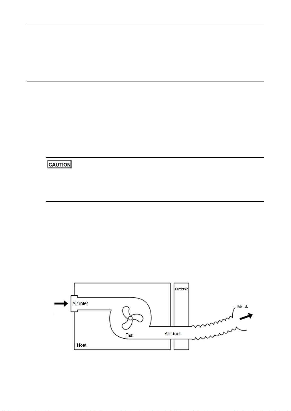
1.2 Operation Theory
OSAS usually performs as airway obstruction, disturbance in respiration, which may cause
respective complications. The CPAP Ventilator uses dedicated air compressor to compress filtered
air from the surrounding environment to produce continuous positive pressure. The positive pressure
is transported to the patient through a breathing tube. The upper airway of the patient is kept open
under the positive pressure so that the patient can breathe normally. The working principle of the
CPAP Ventilator is illustrated by Figure 1-1.
Figure 1-1 Operation Theory
If the positive pressure is set to an excessively low value, the effect of treatment will be affected; if
the positive pressure is set to an excessively high value, the patient will feel uncomfortable.

1 Overview
2
Therefore, the patient must undergo pressure titration in hospital before using the CPAP Ventilator. A
licensed physician will present a report on usage pressure and perform pressure titration for the
patient.
The CPAP Ventilator is operated by using the display screen and control buttons on top of the
ventilator. The device functions are adjustable. The CPAP Ventilator is fitted with a heated humidifier,
which is used to increase the temperature and humidity of the breathed air so as to prevent mucosa
drying in nasal cavity and ensure comfort of the patient.
1.3 Warnings, Cautions and Contraindications
1.3.1 Warnings
Read and understand the entire user manual before operating this device.
This device is not intended for life support.
This device can be used only after completion of treatment parameter settings under the
instruction of a licensed physician.
The instructions in this manual are not intended to supersede established medical protocols.
This device must be used together with the accessories (such as the mask, tube, and power
adapter) recommended and provided by Dymind Biotech. The use of accessories other than
those specified may have an adverse effect on device functions.
When connecting the power adapter, check whether the plug is connected to the device's power
interface properly.
This device is not suitable for use in the presence of a flammable anaesthetic mixture in
combination with oxygen or air.
Take off the mask in the case of power failure or in the unlikely event of fault conditions.
Do not block the vent holes of the mask. If the vent holes are blocked, the patient will repeatedly
breathe in exhaled air, which may cause suffocation.
To avoid scald, do not touch the warm-up plate of the heated humidifier when it is operating.
Discontinue use if you notice any exceptions of the device, such as significant external damage,
liquid ingress, excessively hot output air, or unusual sounds.
Do not perform repair or maintenance when the device is operating.
Power supply is specified as a part of this equipment, be sure to use this power supply, or would
result in electric shock and other hazards.
It can be unsafe to interconnect the device with other equipment not described in this manual.
Bundle or place the cables and hose properly to advoid strangulation due to excessive length.
Device and system should not be close to other devices or stack. Or it should be observed and
verified that it can work normally under his setting, if it has to be closed to other device or stack.
It's possible to lead to the increasing of electromagnetic radiation of the device and system , or
the decreasing of noise immunity if accessory and electric cable which are out of stipulation are
used, except for the electric cable which are sold as spare parts of internal components by the
manufacturer of the device and system.

1 Overview
3
1.3.2 Cautions
Before turning on the device, make sure the power supply is steady and meets the requirements.
The use of communications equipment, electromechanical equipment, or MRI equipment near
this device may cause interference to this device and should be kept at a distance.
Do not dissemble or repair the device without authorization. Contact your device supplier if the
device is damaged.
Do not immerse the host in any fluids or place the host in an excessively hot and humid
environment.
Disconnect the power cord when the device is not in use.
In the home healthcare environment that can unacceptably affect the basic safety and essential
performance of the device, please make sure to keep the device away from:
lint, dust, light (including sunlight), etc.
pet, pest and children.
Irregular sleep, drinking, fat, obesity, hypnotic or sedatives may aggravate the symptoms
1.3.3 Contraindications
The device is prohibit to use, if patient is among any case below:
Pulmonary bulla indicated by a chest CT scan or X-ray
Pneumothorax, pleural effussion or pneumomediastinum
Hypotension, such as when shock is not treated immediately
Severe coronary heart disease (CHD)
Cerebral spinal fluid leak, traumatic brain injury (TBI), or intracranial pneumatocele
Acute otitis media
Facial trauma, postoperation, deformity
Tacheal secretions excess, sputum excretion
Afer abdominal operation
1.4 Symbols
The symbols that may be found in this document are defined as follows.
Symbol
Description
WARNING
Alerts you to injury if not operating based on the description under
this symbol.
Alerts you to device damage if not operating based on the
description under this symbol.
You may find the following symbols of the ventilator system:

1 Overview
4
Symbol
Description
Alerts you to injury if not operating based on the description under
this symbol.
Serial Number of the product
Date of manufacture
Manufacturer
IP21
Ingress protection
Type BF applied part
Refer to instruction manual
European CE declaration of conformity
Authorized Representative in the European Community
1.5 Quality Guarantee
For failures caused by material and manufacturing, Dymind Biotech offers a 2-year warranty on the
host, a one-year warranty on the heated humidifier and a three-month warranty on accessories suc
h as the tubing, mask, and water tub. The warranty period starts from the date of shipment to the cu
stomer. Within the warranty period, Dymind Biotech offers repair service without charge in
accordance with warranty obligations.
If you require the electrical diagram or component list of theCPAP Ventilator in special situations
(such as maintenance or connection to other devices), contact Dymind Biotech. We will provide you
with part of or the entire electrical diagram of the CPAP Ventilator based on your requirements.
You can get repair service without charge only after producing the warranty card filled in upon
purchase of the CPAP Ventilator.
1.6 Disposal
The user of the CPAP Ventilator is required to dispose of the device and related packing materials
based on applicable national laws and regulations when the device reaches the end of service life.
Observe the following disposal instructions unless otherwise specified:
Send the device that has reached the end of service life to a recycle center. The recycle center
enables the user to dispose of the plastic, glass, metal components, printed tube board (PCB),
cable, battery, warm-up plate of the heated humidifier, and motor of the device.
Send the hardboard package and protective plastic package to the recycle center.
2 Installation and Configuration
5
2 Installation and Configuration
2.1 Device Composition
The CPAP Ventilator consists of a host, humidifier, air tubing, mask, and power adapter (100–240 V
AC, 50/60 Hz, 24 V DC).
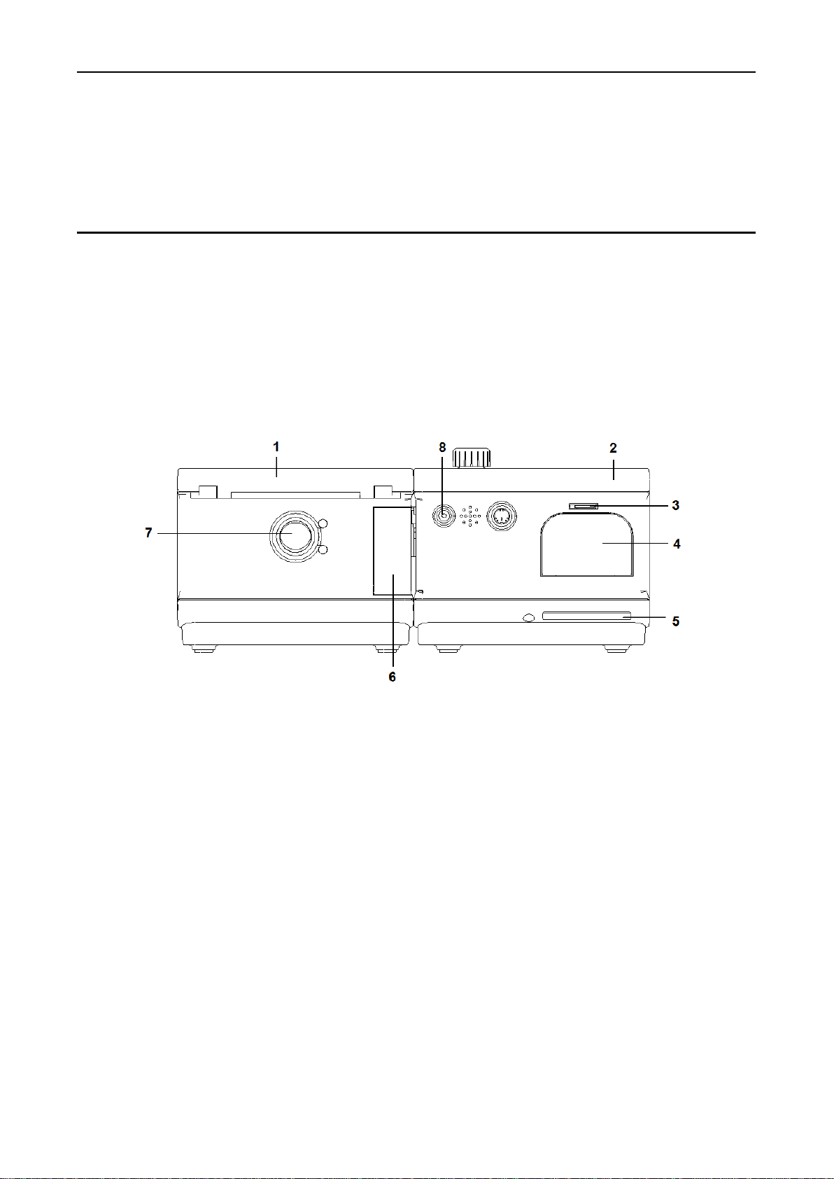
2.2 Interfaces
1- Host
2 - Humidifier
3 - SD card: storing treatment data for up to a year
4–Air filter and air filter cover: air filter which is used for filtering the dust in the air within device can
be installed after filter cover is opened.
5- Air inlet
6- Humidifier separation button: press this button and pull in 2 opposite directions simultaneously,
then the host and humidifier will be separated.
7- Air outlet: connected to the tubing
8- DC power: connected to the DC power adapter
2.3 Installation
Take the following steps to install the CPAP Ventilator:
1. Connect the host to the heated humidifier.

2 Installation and Configuration
6
In alignment with the air channel and electrical connection of the humidifier, gently push the host
so that the connecting clip of the host and that of the humidifier are locked to each other.
2. Inject water into the water tub.
a. Press the OPEN button of the humidifier. When the cap pops up, lift the cap and take out
the water tub.
b. Pour a proper amount of purified water into the water tub. Be sure not to exceed the highest
water level.
c. Insert the water tub into the humidifier and gently press on the cap.
Only purified water can be added to the water tub. If running water or mineral water is added,
incrustation will occur, affecting the service life of the water tub.
3. Install the air filter.
Gently pinch on both sides in the lower part of the air filter cover, take off the cover, insert the air
filter into the cover, insert the upper part of the cover into the pilot hole, and press the lower part
of the cover so that the cover is locked.
4. Install the microSD card.
5. Connect to the tubing and put on the mask.
a. Connect one end of the tubing to the air outlet of the humidifier and the other end to the
mask with the exhalation port.
b. Gently fit the mask onto your nose, adjust the mask, and gently tighten the four elastic
bands until you have a comfortable fit.
6. Connect to a power supply.
Connect the DC power plug of the power adapter to the DC power interface on the back of the
ventilator and connect theAC power plug to the AC power socket.
After power-on, the Home screen of the ventilator appears on the display screen (Figure 2-1).
Figure 2-1 Home screen
The ventilator enters the power-on standby state after being connected to a power supply. The
button is used to start or stop pressure output.
The temperatures on both sides of the DC power adapter increase when the ventilator is
operating. It is a normal phenomenon.
Place the ventilator on a firm and flat surface away from any heating or cooling equipment (such
as fans, radiators, or air-conditioners). Do not block the vent holes with objects and ensure
normal air circulation inside the ventilator.

2 Installation and Configuration
7
2.4 Operation Panel
1 - Control Wheel/Push Button: Use this button to select a menu option and confirm the selection.
The control wheel button supports three operations: pressing (for confirming the selection),
rotating clockwise, and rotating counterclockwise.
Pressing: When the control wheel is pressed on the parameter setup screen, the specified
function is selected.
Rotating clockwise/counterclockwise: When the control wheel is rotated in the menu column,
the previous/next menu option is selected. When the control wheel is rotated in parameter
options, different values are selected or the value of the specified parameter is increased or
decreased.
When the control wheel is pressed and held for 3s on the Humidity Level screen, the
temperature and humidity levels of the humidifier are increased if the ventilator is not in
Warming Up or Cooling Down state. If the ventilator is in Warming Up state, the
temperature and humidity levels of the humidifier are reduced.
2 - Display screen:A menu, treatment information, and alarm information appear here.
3 - :Use this button to start or stop treatment.
4 - : Use this button to view the patient's sleep quality report and the ventilator's service
information.
5 - : Use this button to set parameters.
Press the button to enter the user setup screen. Basic parameters such as Mask Fit,
Tube, and Mask can be set. See section 2.5.3 "User Setup".
Press and held the button and control wheel at the same time for 3s to enter the
detailed setup screen. Detailed treatment parameters such as Work Mode, Humidity Level,
and Xlief can be set. See section 2.5.4 "Detailed Setup".
6 - :Use this button to cancel the current operation or return to the previous screen.

2 Installation and Configuration
8
2.5 Batch Parameter Settings
The user can set the treatment parameters quickly though Micro SD.
(Note: Users can set all parameters of device , for details, see 3 Parameter Settings.)
The procedure is as below :
1. Abtain the configuration file from your local agent.
2. Finish the customization of configuration file with the help of your local agent.
3. Copy the configuration file to Micro SD.
4. Insert the Micro SD into the host, Press button 3 seconds under stand-by condition.
The system will input the configuration file , and finish the parameter setting.
13 parameters can be set in the configuration file. See Table 2-1.
Table 2-1 Parameter settings in configuration file
No.
Parameter
Value
1
Mode
CPAP, APAP
2
Treat Pressure (for CPAP only)
4~20 hPa
3
Max Pressure (for APAP only)
4~20 hPa
4
Min Pressure (for APAP only)
4~20 hPa
5
Start Pressure for CPAP only (the initial pressure
output when the ramp feature is enabled.)
4~20 hPa
6
Start Pressure for APAP only (the initial pressure
output when the ramp feature is enabled.)
4~20 hPa
7
Max Ramp
0~60 min
8
Xlief
1~3
9
I-sensitivity
1~5
10
E-sensitivity
1~5
11
I-rate
1~3
12
Smart Start
On, Off
13
Humidity Level
1~6
3 Parameter Settings
9
3 Parameter Settings
The parameters on the user setup screen (press the button to enter the screen) can be set by
the patient. Other parameters must be set by a licensed physician or under the instruction of a
licensed physician.
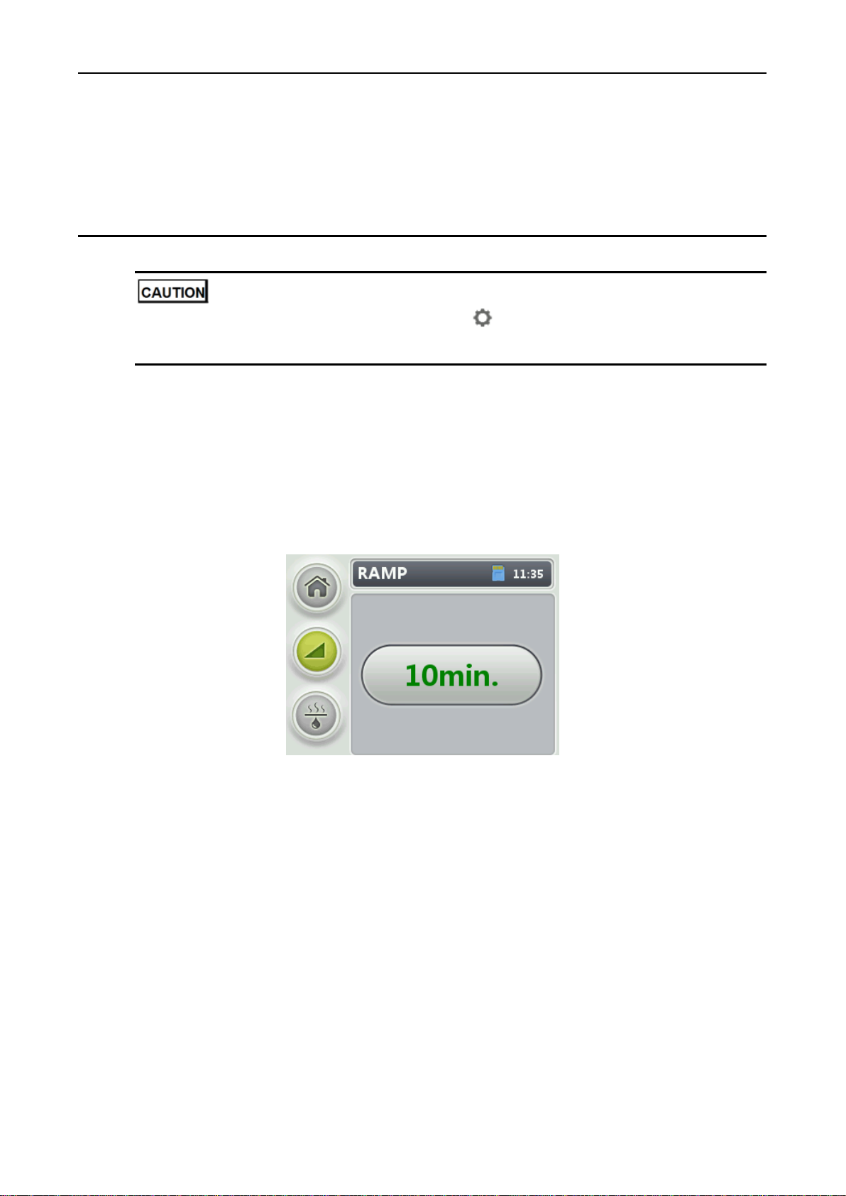
3.1 Ramp Time
You can set ramp on the Home screen to increase the treatment comfort degree. (The ramp feature
is disabled by default.)
1. On the Home screen, rotate the control wheel to the RAMP menu and press the control wheel to
enter the RAMP screen (see Figure 3-1).
Figure 3-1 Setting the ramp time
2. Rotate the control wheel to select the ramp time and press the control wheel to confirm the
selection.
When the ramp feature is enabled, the ventilator outputs an initial pressure and slowly increases
the initial pressure to the therapeutic pressure during the predefined ramp time to help the
patient fall asleep. When the ramp time ends, the ventilator automatically detects the patient's
respiration conditions and adjusts pressure accordingly.
For details about the setting of the ramp time, see section 3.4.1 Detailed Treatment Settings.
3.2 Humidity Level
When the host is connected to the heated humidifier, you can set the humidity level for the warm-up
of the humidifier to ensure that the air output by the ventilator has a proper temperature when being
humidified.
Rotate the control wheel to the Humidity Level menu and press the button to enter the Humidity

3 Parameter Settings
10
Level screen.
Setting the humidity level
Rotate the control wheel to select a humidity level for the humidifier and press the button to
confirm the selection (see Figure 3-2).
Figure 3-2 Setting the humidity level
The level of humidity can be set before or after cure. The value of Humidity Level ranges from 1
to 6, or it can be set to Off.
(When Humidity Level is not set to Off) Warming up or cooling down
Before starting treatment, press and held the control wheel for 3s. If the ventilator is not in
Warming Up or Cooling Down state, the temperature and humidity levels of the humidifier are
increased (see Figure 3-3). If the ventilator is in Warming Up state, the temperature and
humidity levels of the humidifier are reduced (see Figure 3-4).
Figure 3-3 Warming up
Figure 3-4 Cooling down
During treatment, the ventilator will stop warming when the treatment is stopped.
Stop warming or cooling
Rotate the control wheel to Off to stop warming or cooling.

3 Parameter Settings
11
Figure 3-5 Stop warming or cooling
Humidity Level is set to a proper value if small drops of condensed water exist inside the groove
of the tubing in the next morning. Humidity Level is set to an excessively large value if many
water droplets exist inside the tubing and mask; Humidity Level is set to an excessively low
value if you feel nose dryness; in these cases, reduce or increase the value of Humidity Level.
When you lie down, keep the ventilator slightly lower than your head so that drops of condensed
water flow back to the water tub of the humidifier to prevent respiratory impairment.
Empty water in the water tub of the humidifier when it is not used.
3.3 User Setup ( Button)
Press the button to enter the user setup screen (see Figure 3-6).
Figure 3-6 User setup screen
The following parameters can be set by the patient.
Rotate the control wheel clockwise or counterclockwise to switch to other menus or options. Press
the control wheel button to confirm the settings, or press the button to cancel the settings.
Parameter
Setting Description
Tube
This parameter specifies the tubing type: Standard (diameter: 22 mm)
3 Parameter Settings
12
Parameter
Setting Description
Mask
This parameter specifies the mask type.
Values: Nasal, Full Face
Xlief
The ventilator automatically detects respiratory rhythm when it is operating and
reduces the pressure inside the mask during exhalation to increase the patient
comfort level. The higher the parameter value, the higher the pressure release
level.
The default value is 3.
Values: 3, 2, 1, Off
NOTE
The Xlief parameter appears on the user setup screen only when the Xlief parameter on
the detailed setup screen is set to Patient by a licensed physician.
I-sensitivity
The inspiratory trigger sensitivity (ITS) of the device.
The range is between 1 and 5, and the default value is 3. The higher the value,
the higher the sensitivity.
NOTE
The I-sensitivity appears on the user setup screen only when the I-sensitivity
parameter on the detailed setup screen is set to Patient by a licensed physician.
E-sensitivity
The expiratory trigger sensitivity (ETS) of the device.
The range is between 1 and 5, and the default value is 3. The higher the value,
the higher the sensitivity.
NOTE
The E-sensitivity appears on the user setup screen only when the E-sensitivity
parameter on the detailed setup screen is set to Patient by a licensed physician.
I-rate
The inspiratory flow rate (IFR) of the device.
The range is between 1 and 3, and the default value is 2. The higher the value,
the greater the flow rate.
NOTE
The I-rate appears on the user setup screen only when the I-rate parameter on the
detailed setup screen is set to Patient by a licensed physician.
Mask Fit
Press the control wheel to start the mask fit function; or press the button to
stop.
When the mask does not have air leaks, a prompt is displayed indicating that
the mask is worn properly.
When the mask has air leaks, a prompt is displayed indicating that the mask
needs to be adjusted.
If the patient does not stop the mask fit function halfway, the ventilator will
automatically start treatment 3 minutes after the mask is put on.
Smart Start
When the ventilator is in standby state and the patient puts on the mask and takes
deep breathing 2~3 times, the ventilator is started automatically and outputs the
predefined pressure. Once the mash is taken off, the therapy will be stopped.
Values: On, Off
NOTE
The Smart Start parameter appears on the user setup screen only when the Smart Start
parameter on the detailed setup screen is set to Patient by a licensed physician.

3 Parameter Settings
13
3.4 Detailed Setup ( Button + Shuttle Button)
The parameters on the detailed setup screen must be set by a licensed physician or under the
instruction of a licensed physician.
Press and held the button and control wheel at the same time for 3s to enter the detailed setup
screen (see Figure 3-7). The treatment parameters, reminder parameters, and system configurations
can be set.
3.4.1 Detailed Treatment Settings
Rotate the control wheel clockwise or counterclockwise on the Setup screen to switch to other
menus or options. Press the control wheel to confirm the settings, or press the button to cancel
the settings.
Figure 3-7 Detailed setup screen
Parameter
Setting Description
Mode
This parameter specifies the work mode of the ventilator. Please set it
according to the actual situation.
CPAP: short for Continuous PositiveAirway Pressure. The device can
provide continuous CPAP according to the different condition of patient.
APAP: short for Automatic Continuous Positive Airway Pressure. The
device can adjust and find the best curing pressure automatically
according to the sleep condition of patient.
CPAP
Treat
Pressure
This parameter specifies the maximum therapeutic pressure in CPAP mode.
Value range: 4.0~20.0. The default value is 5.0.
APAP
Max
Pressure
This parameter specifies the maximum therapeutic pressure in APAP mode.
The default value is 20.0.
Min
Pressure
This parameter specifies the minimum therapeutic pressure inAPAP mode.
The default value is 4.0.
Start Pressure
This parameter specifies the initial pressure output by the ventilator when the
ramp feature is enabled.
NOTE
The parameter is displayed only when Max RAMP is not set to Off.
3 Parameter Settings
14
Parameter
Setting Description
Max RAMP
This parameter specifies the maximum ramp time. Values:
Off: to disable the ramp feature.
5 minutes/10 minutes/…/55 minutes/60 minutes: user-defined maximum
ramp time. If Max RAMP is set to 10 minutes, Ramp Time on the Home
screen can be set to OFF, 5 minutes, or 10 minutes.
NOTE
The ramp feature enables slow increase of the therapeutic pressure from the
minimum pressure to the maximum pressure during the maximum ramp time, so that
the patient can fall asleep more comfortably.
Xlief
The ventilator automatically detects respiratory rhythm when it is operating
and reduces the pressure inside the mask during exhalation to increase the
patient comfort level. The higher the parameter value, the higher the pressure
release level. The default value is 3.
Values: 3, 2, 1, Off, Patient.
NOTE
When the parameter is set to Patient, the Xlief parameter appears on the user setup
screen and can be set.
I-sensitivity
The inspiratory trigger sensitivity (ITS) of the device. The higher the value, the
higher the sensitivity. The default value is 3.
Values: 1, 2, 3, 4, 5, Patient.
NOTE
When the parameter is set to Patient, the parameter appears on the user setup
screen and can be set.
E-sensitivity
The expiratory trigger sensitivity (ETS) of the device, including: 1~5, Patient.
The default value is 3. The higher the value, the higher the sensitivity.
NOTE
When the parameter is set to Patient, the parameter appears on the user setup
screen and can be set.
I-rate
The inspiratory flow rate (IFR) of the device.
The default value is 2. The higher the value, the higher the flow rate.
Values: 1, 2, 3, Patient.
NOTE
When the parameter is set to Patient, the parameter appears on the user setup
screen and can be set.
Mask
This parameter specifies the mask type.
Values: Nasal, Full Face
Tube
This parameter specifies the tube type: Standard (diameter: 22 mm)
Smart Start
When the ventilator is in standby state and the patient puts on the mask and
takes deep breathing 2~3 times, the ventilator is started automatically and
outputs the predefined pressure. Once the mash is taken off, the therapy will
be stopped.
Values: On, Off, Patient.
NOTE
When the parameter is set to Patient, the Smart Start parameter appears on the
user setup screen. To enter the user setup screen and enable/disable the Smart
Start function, press the button.
3 Parameter Settings
15
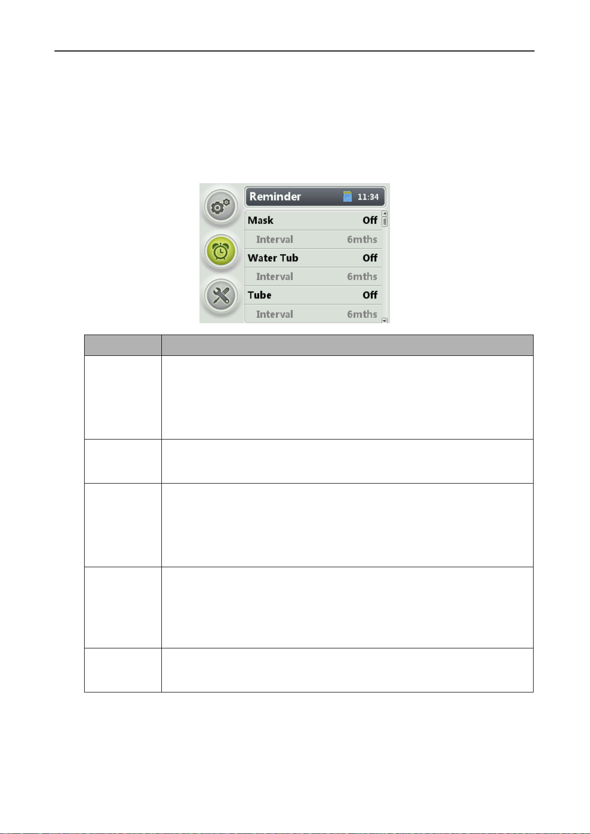
3.4.2 Reminder Configuration
Rotate the control wheel to the Reminder menu on the Setup screen and press the button to enter
the Reminder screen (see Figure 3-8). On the Reminder screen, the operator can set the time for
notifying the patient of replacing components or the time for device maintenance.
Figure 3-8 Reminder screen
Parameter
Setting Description
Mask
This parameter specifies the time for notifying the user of contacting his/her device
supplier to replace the mask. The default value is Off, indicating that the user is not
notified.
NOTE
The shelf life of mask is 24 months.
It is suggested to change the mask after every 6 months use.
Water Tub
This parameter specifies the time for notifying the user of contacting his/her device
supplier to replace the water tub. The default value is Off, indicating that the user is
not notified.
Tube
This parameter specifies the time for notifying the user of contacting his/her device
supplier to replace the air tubing. The default value is Off, indicating that the user is
not notified.
NOTE
The shelf life of air tubing is 3 years.
It is suggested to change the air tubing after every one year use.
Filter
This parameter specifies the time for notifying the user of contacting his/her device
supplier to replace the filter. The default value is Off, indicating that the user is not
notified.
NOTE
The air filter of the device is not washable. It is suggested to be changed after 3~6 months
use. Please contact your local agent for purchasing.
Service
This parameter specifies the time for notifying the user of sending the ventilator to
his/her device supplier for maintenance. The default value is Off, indicating that the
user is not notified.
Other manuals for DM18 APAP
1
Table of contents
Popular Medical Equipment manuals by other brands

Otto Bock
Otto Bock BEBIONIC small user guide

Dentsply Maillefer
Dentsply Maillefer EASYPOST A0009 Directions for use

GE
GE LOGIQ V2 Basic service manual

Advanced Circulatory
Advanced Circulatory ResQCRP ResQPUMP ACD-CPR Instructions for use

Nidek Medical
Nidek Medical Nuvo 10 quick start guide

Cytori Therapeutics
Cytori Therapeutics celution GP Quick reference guide

LUMENIS
LUMENIS Array LaserLink Operator's manual

Stream DX
Stream DX Uroflowmeter user manual

WillowWood
WillowWood ONE User instructions

LPG
LPG WELLBOX S Installation and user guide

Zeiss
Zeiss CLARUS 500 Instructions for use

Amico
Amico LightMaster Multifunction Switch Operating and maintenance instructions


